I. About this project:
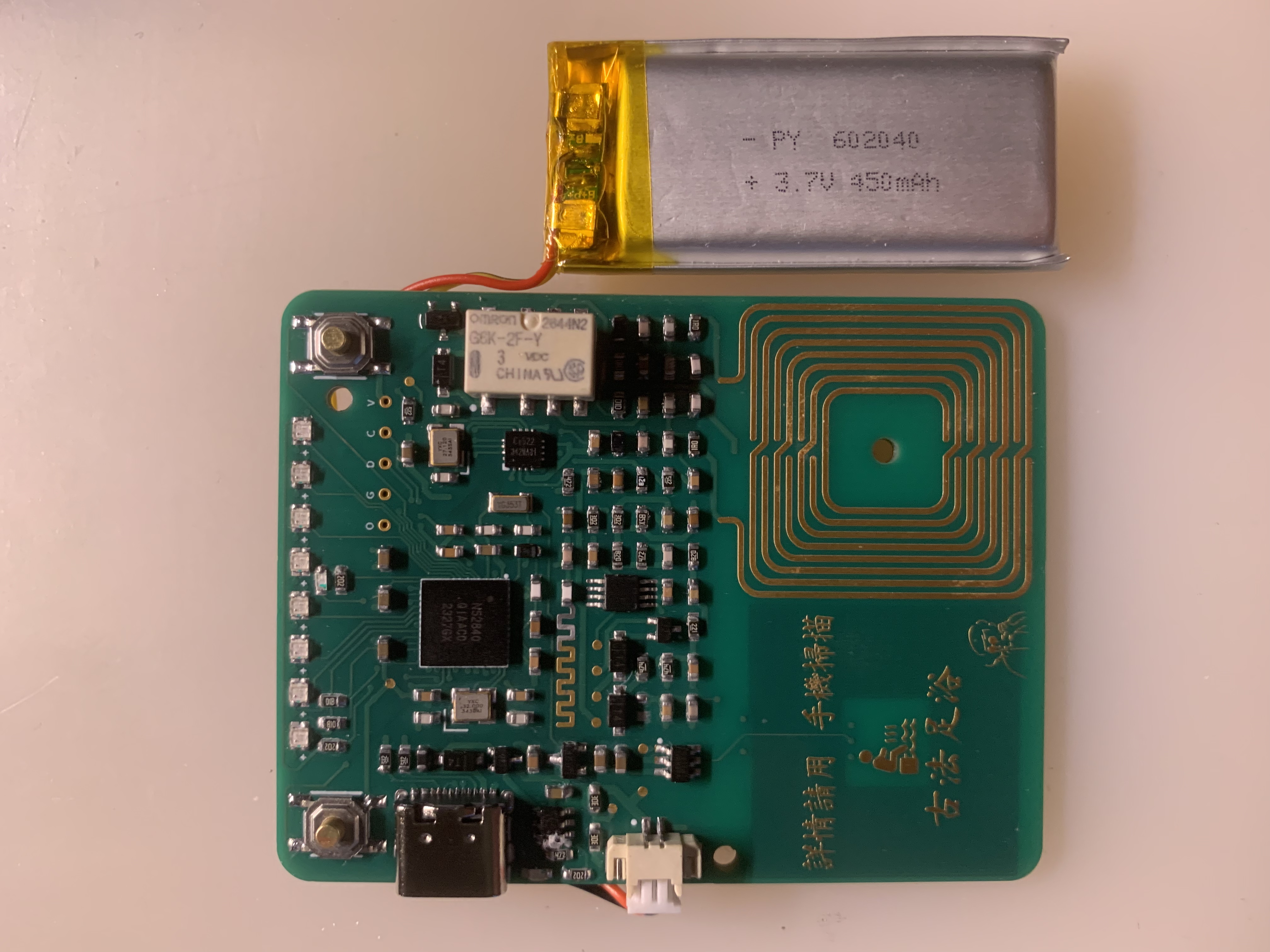
Chameleon is a tool that can clone analog IC (13.56MHz) and ID (125kHz) cards.
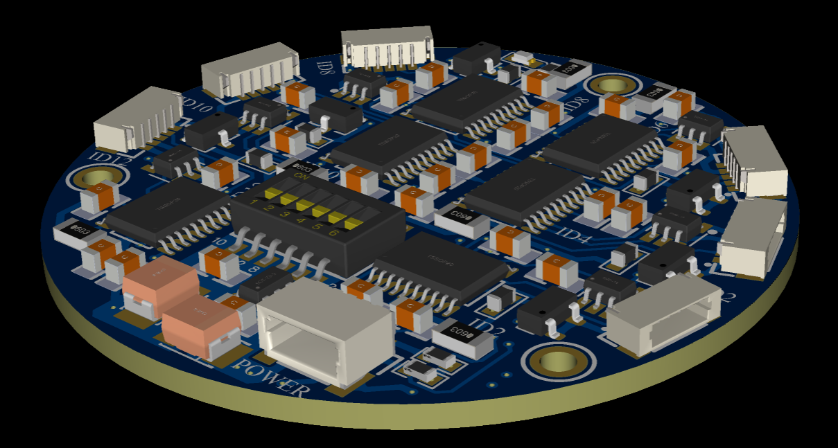
This project is modified from the official original schematic. Replacing the LF coil with a physical coil results in a much better signal than PCB-printed coils.
Two-layer boards allow for more colors. Board thickness is flexible.
Verified, a six-layer Dev Mini version is also available! The size is reduced, card reading is sensitive, and size is not a factor. Join the group to obtain the PCB design files.
the technical exchange group on Xianyu: 823366985. Everyone is welcome to join the group for discussion.
The minimum system board for STM32G431CBU6 has built-in STLINK, which can be used for debugging or programming external STM32 microcontrollers.
This project is the first open-source release across the entire platform, providing beginners with a low-cost STM32 minimum system board
. 1. This system board brings out almost all general-purpose GPIO pins.
2. It has a built-in STLINK V2.1 with a serial port and virtual USB drive drag-and-drop programming, making it convenient and quick to use. It can also be used as a debugger to program or debug external STM32 boards.
3. The system board includes an external operational amplifier for the microcontroller.
4. It has a built-in MAX6675 chip for direct thermocouple temperature measurement.
5. It has two LCD screen interfaces (the two cannot be used simultaneously), allowing direct connection of the screen to the system board without an adapter board.
6. Its size is compatible with common STM32F103C8T6 minimum system boards, allowing direct insertion onto a breadboard.
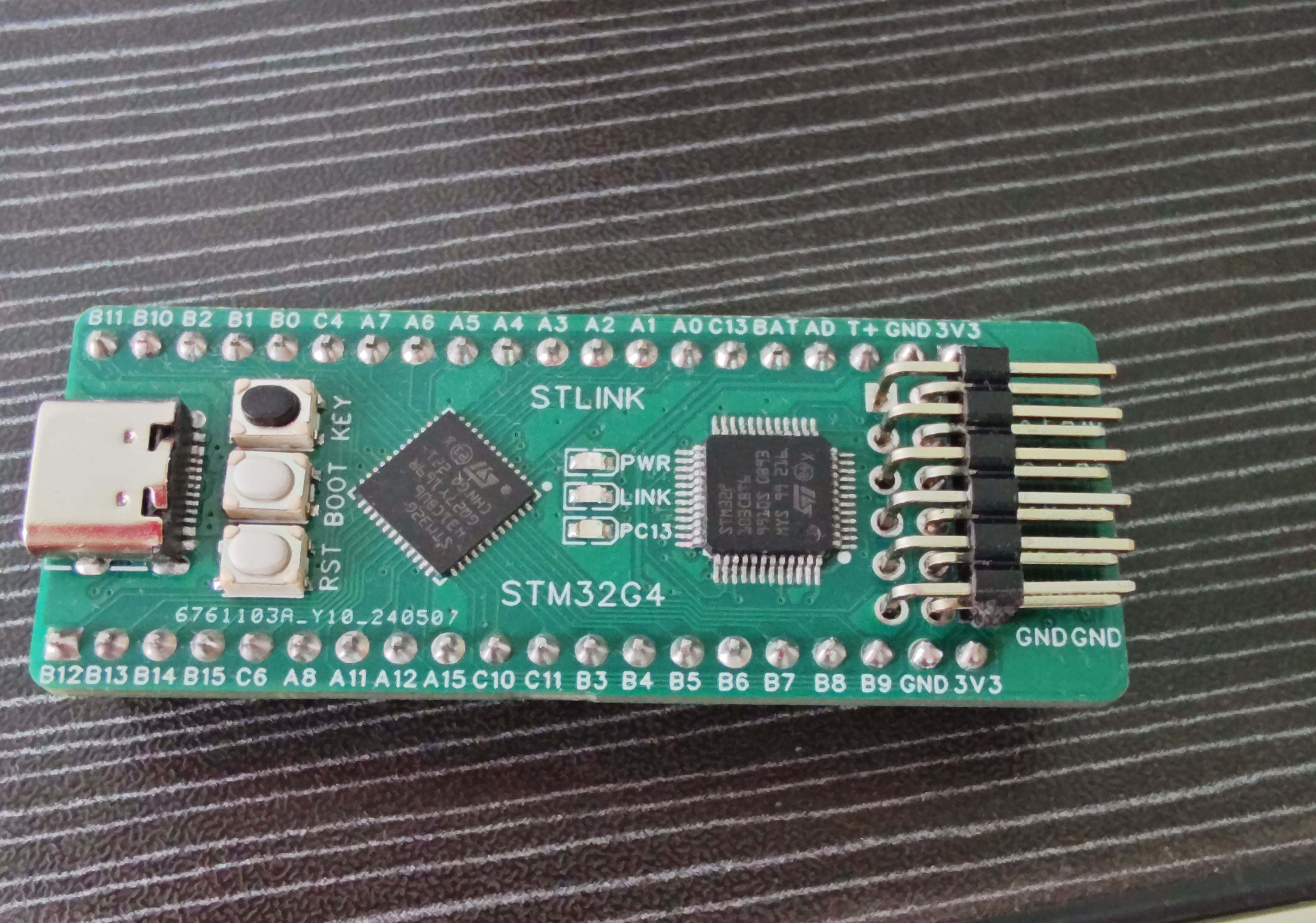
7. The board uses a common Type-C power supply interface and includes a user button, a user LED, a power indicator LED, and STLINK status indicator lights. The
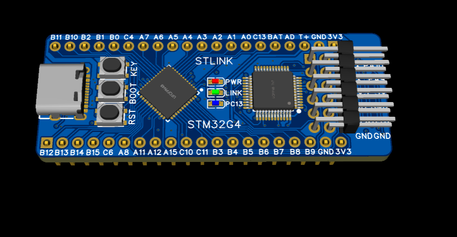
actual product after soldering is shown in the image.
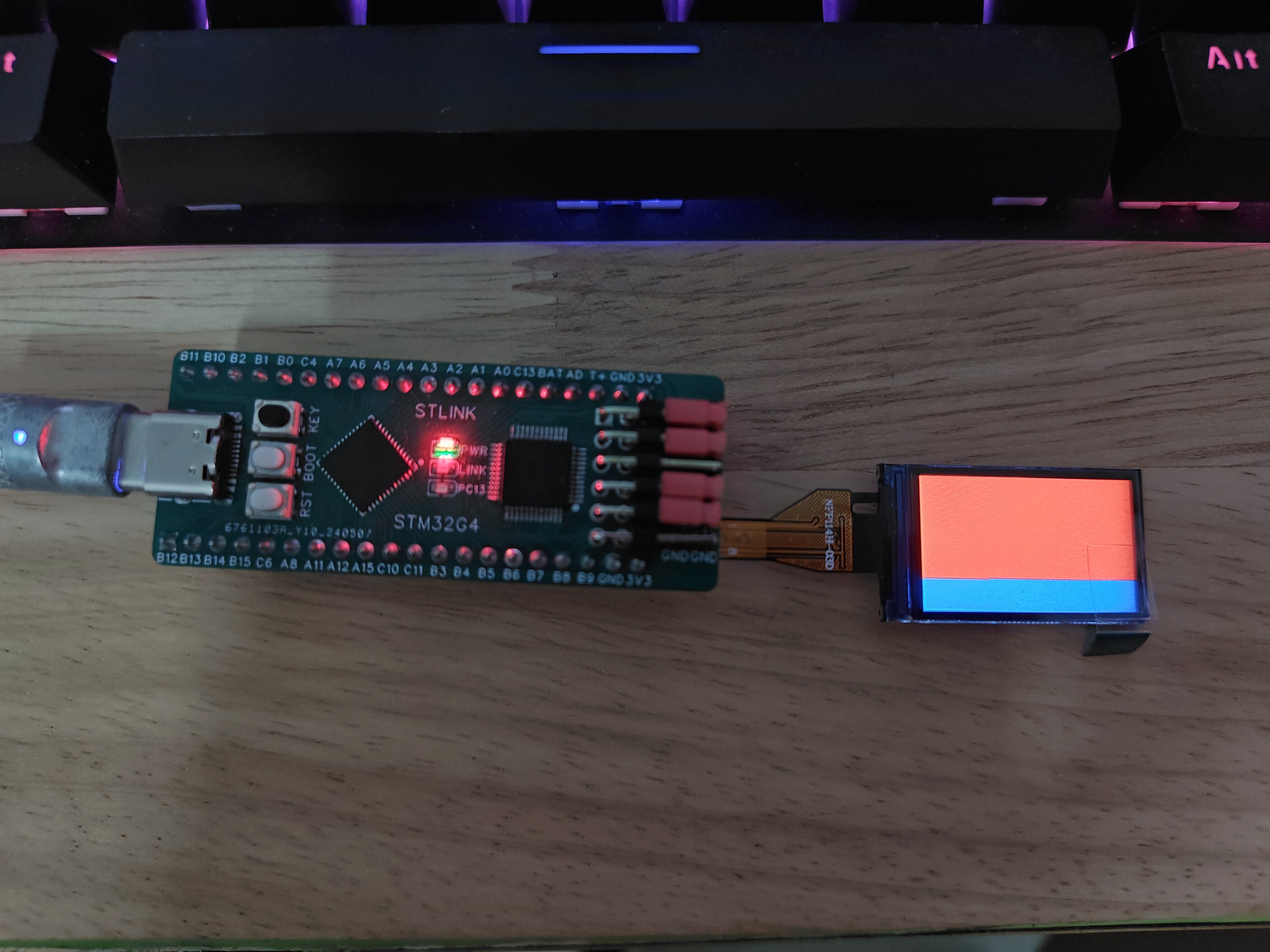
The built-in STLINK is connected to the utility
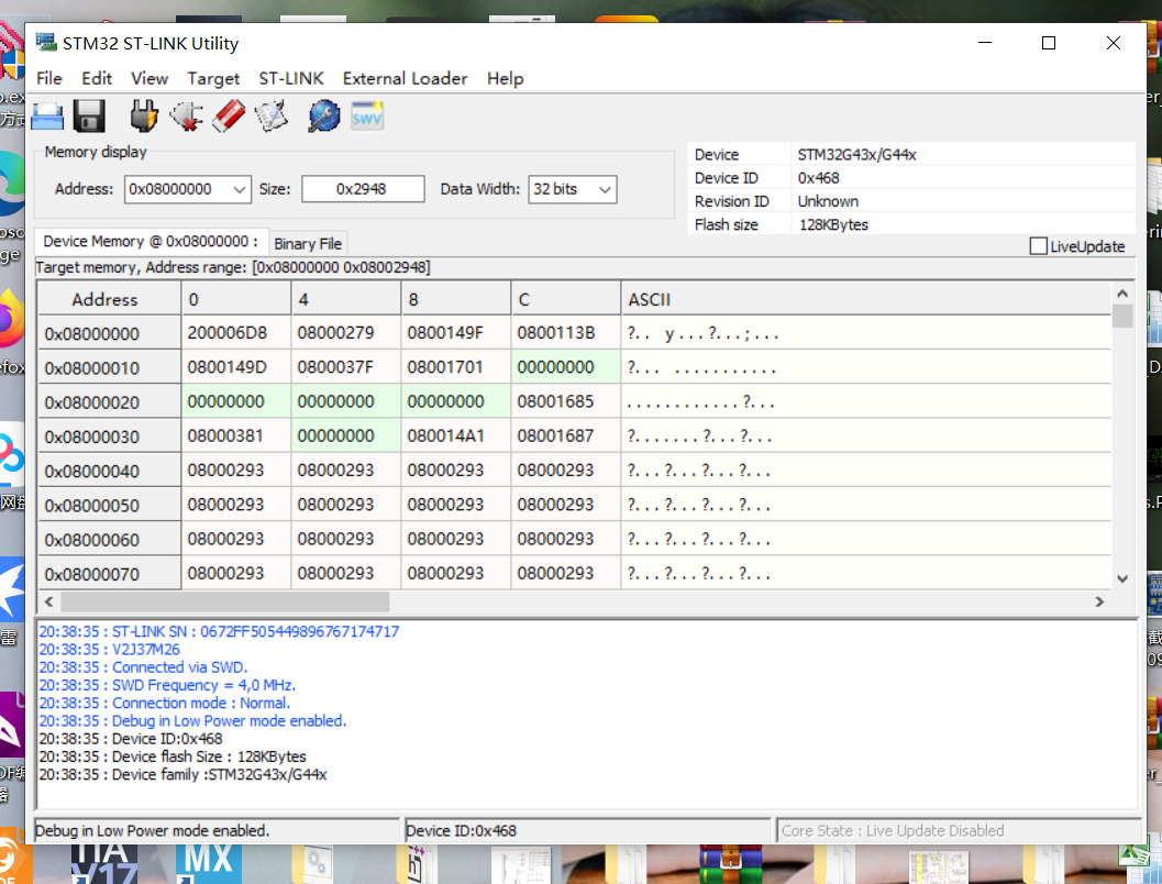
STLINK via USB

. Using Keil software, the connection is successful, displaying the V2.1 version serial number

and lighting up the LCD screen.
V20240707-203746.mp4
V20240514-134129.mp4
PDF_STM32G431 Development Board Built-in STLINK.zip
Altium_STM32G431 development board with built-in STLINK.zip
PADS_STM32G431 development board with built-in STLINK.zip
BOM_STM32G431 development board has built-in STLINK.xlsx
93914
IAP15F2K61S2 LQFP44 to DIP40
I'm self-studying 51 microcontrollers and using the STC IAP15F2K61S2 emulator. It has a DIP40 package, but its pinout differs from the traditional 8051 microcontroller, making it unsuitable for traditional development boards. So I designed my own LQFP44 to DIP40 adapter board (which has already been fabricated).
IAP15F2K61S2 LQFP44 to DIP40 Adapter Board
Version Notes - 2024.7.7
1. Added external crystal oscillator selection pins P1.6 and P1.7.
2. Added external reset selection pin P54.
3. DIP40 pins 29, 30, and 31 are left floating; jumpers can be soldered later if needed.
4. The pin definitions are the same for STC15F/STC15W series LQFP44 packages and should also be applicable.
5. V1 is my first board design with absolutely no prior experience; it features automatic routing, no copper plating, and is already fabricated.
6. V2 is a modified version of V1, optimized after watching EDA video tutorials; DRC checked and found no errors; no copper plating; not yet fabricated.
7. I only have a junior high school education, and my work has nothing to do with electronics; I designed this out of hobby in my spare time, hoping it will be helpful to others. Please correct any shortcomings yourself.
Version V1 is already fabricated, tested and downloadable; all I/O LEDs are working.
Detecting target microcontroller...
Microcontroller model: IAP15F2K61S2
Software protocol: 7.2.5S
Current chip hardware options are:
. After the next cold boot, the system clock source is the internal IRC oscillator
. Current oscillator frequency: 22.078MHz
. . Oscillator amplification gain enabled
. . Power-down wake-up timer frequency: 34.525KHz
. . P3.2 and P3.3 are irrelevant to the next download
. . No additional reset delay is added during power-on reset
. . The reset pin remains the reset pin
. . Reset upon low voltage detection
. . Low voltage detection threshold voltage: 3.82V
. . EEPROM operations cannot be performed under low voltage
. . The internal watchdog timer is not activated during power-on reset. .
The prescaler for automatically activating the internal watchdog timer upon power-on is: 256.
. The watchdog timer stops counting in idle state
. . After the watchdog timer is activated, the software can modify the prescaler, but cannot disable the watchdog timer
. The user EEPROM area will not be erased during the next user program download
. There is no related 485 port control during the next user program download
. The download password does not need to be verified during the next download
. TXD and RXD are independent I/O pins
. After chip reset, the TXD pin is a weak pull-up bidirectional port
. After chip reset, P2.0 outputs a low level
. Internal reference voltage: 1239 mV (reference range: 1150~1320mV).
Microcontroller model: IAP15F2K61S2.
Software protocol: 7.2.5S.
1720367037393.jpg
VID_20240707_233841_20247723477.mp4
Test program.PNG
PDF_IAP15F2K61S2 LQFP44 to DIP40.zip
Altium_IAP15F2K61S2 LQFP44 to DIP40.zip
PADS_IAP15F2K61S2 LQFP44 to DIP40.zip
BOM_IAP15F2K61S2 LQFP44 to DIP40.xlsx
93915
TPS7A49-LDO module
TPS7A49, low noise, high PSRR, adjustable low dropout voltage regulator
Chip Description: TPS7A49 The
TPS7A49 is a 150mA, 36V, low-noise, high PSRR, adjustable low-dropout regulator with enable function.
Electrical Characteristics:
Input Voltage: 3V~36V
; Continuous Output Current: 150mA;
Output Voltage: 1.194V~33V.
Circuit Description:
A 5.082P connector is used as the main input and output interface of the module. A 2.543P header connector is added for extended power input and output for ease of use.
Following the capacitor distribution in the datasheet, 10uF capacitors are used for input and output filtering in conjunction with 100nF capacitors. Note that it is recommended to add a 10nF capacitor to the feedback resistor section to minimize noise and maximize AC performance.
The output voltage can be adjusted by changing the voltage divider resistors R1 and R2; 1% or even 0.1% is recommended.

Note
that the TPS7A49 is often used in conjunction with the TPS7A30 to form a DC-DC converter; pay attention to the positive and negative voltages, as the 7A49 operates on a positive voltage.
When selecting voltage divider resistors, an accuracy of no less than 1% is not recommended, and the feedback line needs careful consideration; it should not be too far from the pins, and a 10nF capacitor should be placed nearby.
PCB layout should ideally follow the datasheet, with the input, output, and chip GND on a single copper trace.
The capacitor voltage rating must be correctly selected. Although this chip supports 36V input, it should not be used for large voltage drop step-down applications, otherwise the temperature will still be very high.
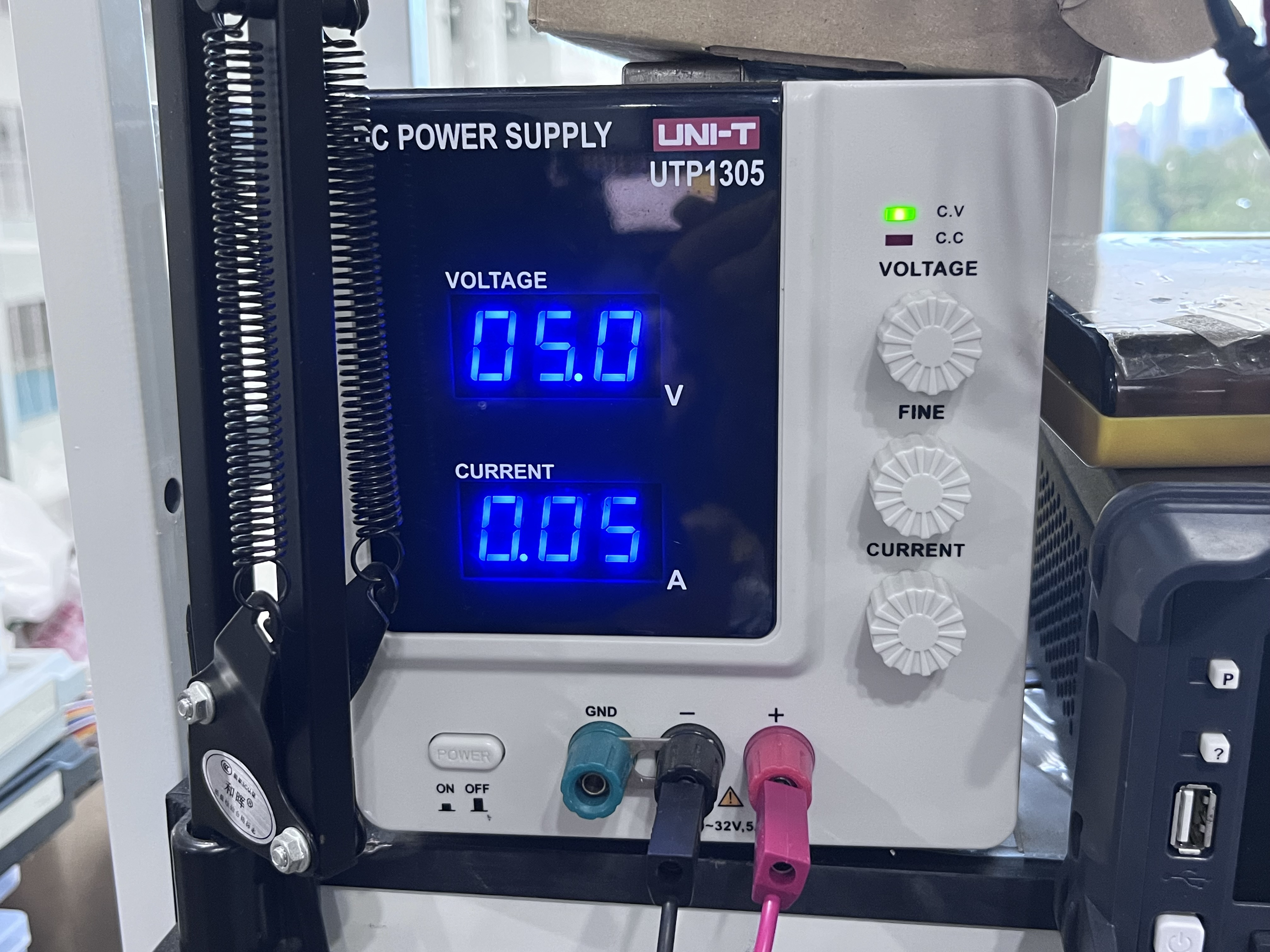
[Actual test image]

PDF_TPS7A49-LDO module.zip
Altium_TPS7A49-LDO module.zip
PADS_TPS7A49-LDO module.zip
BOM_TPS7A49-LDO module.xlsx
93916
Matrix keyboard
Matrix keyboard module
A matrix
keypad is a common input method for electronic devices. It uses a special matrix row and column arrangement to detect and input keys.
A matrix keypad consists of a set of keys (usually buttons or switches) and a matrix circuit. Essentially, it uses 8 I/O ports to control and read 16 keys, thus reducing the number of I/O ports used.
PDF_Matrix Keyboard.zip
Altium_Matrix Keyboard.zip
PADS_Matrix Keyboard.zip
BOM_Matrix Keyboard.xlsx
93917
electronic


 the technical exchange group on Xianyu: 823366985. Everyone is welcome to join the group for discussion.
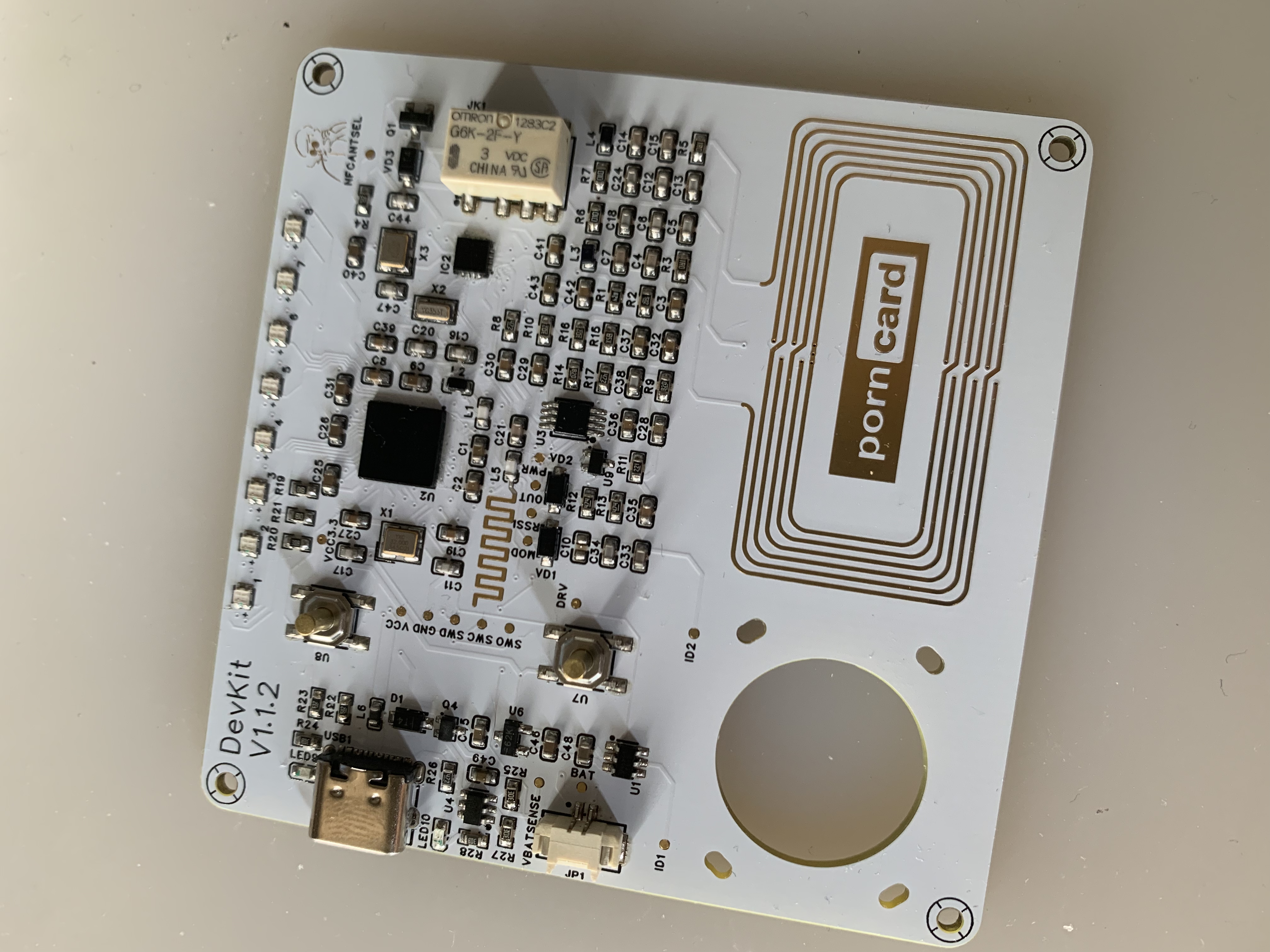


 京公网安备 11010802033920号

 1008HF-120H


