I. Usage Scenarios
This project was specifically developed for a university's LZY series course, supporting all the functions required for "small experiments." It is now open-source for developers to replicate/develop further. You can modify, optimize, or remove unnecessary parts of the project, or add modules as needed. Soldering this project may be challenging; you can leave the more difficult parts blank as described later.
II. Power Supply
This design supports three power supplies:
1. External DC interface {requires soldering a DC-DC circuit (for your health, please do not attempt to connect the DC input to an LDO)}, {if you do not need DC power, this part can be left unsoldered} 2. USB Type
-C interface power supply
3. Downloader power supply
The three power supplies are combined into one via an SS54 and fed into a 3.3V LDO for subsequent circuitry.
III. Clock Introduction
The ATMEGA has an internal RC oscillation circuit. During program download, you can choose to enable the fuse for the internal RC oscillation. If you do not have high clock requirements, you can leave the external crystal oscillator unsoldered.
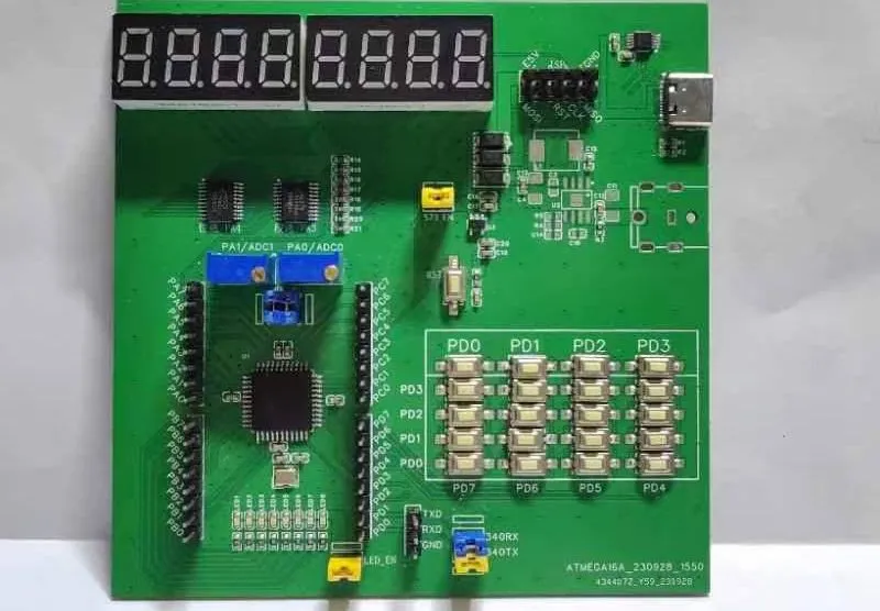
IV. Matrix Keyboard and Independent Buttons:
This project connects the matrix keyboard and independent buttons to the GPIO of group D. The ATMEGA16 has three external interrupt interfaces, two of which are located at PD2 and PD3. Therefore, you can use the interrupt function when using the independent buttons. {You can also expand this project with four AND gates to enable the matrix keyboard to support interrupts.}
V. Digital Tube
: Due to the limited I/O resources of the ATMEGA16, this project uses a 74HC573 latch to drive an 8-digit digital tube. PB0-PB7 are used to control segment selection and digit selection, while PA3 and PA4 are used to latch the 74HC573.
VI. Running Lights:
This project uses PC0-PC7 to drive running lights. All eight running lights are driven by a low level; that is, when the ATMEGA16 outputs a low level, the LEDs light up.
VII. ADC:
This project connects two potentiometers to the PA0 and PA1 pins of the ATMEGA16. You can use PA0 and PA1 to conduct ADC experiments. Please ensure that the internal pull-up resistors of the relevant pins are turned off during the experiment.
VIII. Onboard Serial Port:
This project adds a CH340 Type-C interface for convenient serial port experiments. You can replace the CH340E with other easier-to-solder models.
IX. Download Interface:
This project supports direct connection to common downloaders. You can directly use the 10-pin ribbon cable provided by the downloader seller to connect this development board to the downloader (when soldering the connector, the notch should face downwards).
X. Creative Commons License:
This project uses the CC-BY-SA license. That is:
BY: Attribution;
SA: ShareAlike.


 京公网安备 11010802033920号

 0403-0025-75


