**Related Code** This code, available
at https://github.com/mynewworldyyl/jmicro_stm32
, is ported to STM32. The microcontroller uses this code to connect to the network card for internet access. Other chips can also be ported using this code.
**JMICRO Backend**
Besides supporting general UDP and TCP, this network card further encapsulates the open-source microservice backend project (https://github.com/mynewworldyyl/jmicro) to support remote RPC calls, asynchronous message publishing and subscription. If only UDP or TCP is used, this backend project is not required.
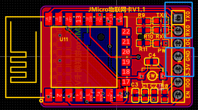
**Network Card and Microcontroller Wiring**
When using the network card, only four wires are needed: 3V3, GND (powering the network card), RX0 of the network card connected to the TX port of the microcontroller, and TX0 connected to the RX port of the microcontroller.
![image.png]
**Network Card Configuration**
Two methods:
Method 1: Directly configure the network in the microcontroller using the following method:
void ICACHE_FLASH_ATTR jm_serial_configWifiPwd(char *ssid, char *pwd);
Method 2: There is a button on the network card. Press it quickly 3 times in a row. The network card will enter AP mode. Connect your computer or mobile phone to the Wi-Fi of this AP (named "JMicro_JXX_Configure Network"). After successful connection, enter 192.168.X.1 (X is usually 4, try starting from 2 if it doesn't work) in your browser to open the following page. Enter the Wi-Fi name and password and submit. If the configuration is incorrect or you need to change the Wi-Fi password, you can repeat the above method to reconfigure.
![Configure Network Webpage.png]

**STM32 Related Notes**
In STM32, the source code uses PA2 and PA3 by default, which is USART2. If you need to use other serial ports, you need to modify the Serial.c source code accordingly.
In STM32, TIM3 is used as the basic time base by default. You can also use other timers, or make sure to call the jm_ElseMs(1) method every millisecond.
**Network Card Programming** This
command-line program requires Python and esptool.py. The relevant bin files are provided in the attached bin.zip file. The output is
: `python "./esptool.py" --port COM6 --baud 115200 write_flash --flash_freq 80m --flash_mode dout --flash_size 4MB 0x0000 "eagle.flash.bin" 0x10000 eagle.irom0text.bin 0x3FB000 blank.bin 0x3FE000 blank.bin 0x3FC000 esp_init_data_default.bin`.
For graphical tool programming, simply refer to the address and corresponding file configuration in the above command.
`0x0000 "eagle.flash.bin" 0x10000 eagle.irom0text.bin 0x3FB000 blank.bin 0x3FE000 blank.bin 0x3FC000` esp_init_data_default.bin
**jm_client API Related Instructions**
Client source code program. A major difference between this network card and other serial network cards on the market is that it provides a complete client API. Whether using TCP, UDP, RPC, or message publish/subscribe, it is very convenient and easy to use. If it is based on JM UDP, the underlying layer has already implemented the assembly and acknowledgment of data packets, ensuring that data packets are accurately and non-repeatedly sent to the other party. The same applies to response data packets.
To send a UDP-based HTTP request, simply call the `jm_udp_sendArray` method: `
char *p = "GET /index.html HTTP/1.1
";
jm_udp_sendArray("192.168.3.4",9092, (uint8_t *)p, jm_strlen(p));`
You can create a web instance on your computer, such as Tomcat, at 192.168.3.4:9092. The microcontroller will return a page or a 404 result, indicating that the UDP connection to the web service has been established, but the page does not exist, hence the 404 page.
**Receiving UDP packets and calling the method**
void _jm_udp_testOnData(const char* host, int port, jm_buf_t *buf){
uint16_t len = jm_buf_readable_len(buf);
for(int i = 0; i data[i+buf->rpos]);
}
}
// Register the method to receive UDP packets
jm_udp_setDataCb(_jm_udp_testOnData);
For complete demo code related to TCP, RPC, and asynchronous messages, please visit the Github project to download the source code.
Currently, the complete TCP and UDP APIs are publicly available. For RPC and message-related APIs, please refer to the jm_client.h header file. The code snippet provided demonstrates
how to send UDP data . uint16_t len); void ICACHE_FLASH_ATTR jm_serial_init(); // Receive UDP datagrams
//void jm_upd_onData(const char* host, int port, jm_buf_t *buf);
//Receive UDP datagrams
void jm_tcp_onData(const char* host, int port, jm_buf_t *buf);
//Receive serial port datagrams
void jm_serial_onData(jm_buf_t *buf);
/**********************************TCP Module Start*********************************************/
//TCP Module Initialization
void ICACHE_FLASH_ATTR jm_tcp_init();
//Method for receiving TCP return data
ICACHE_FLASH_ATTR void jm_tcp_setDataCb(jm_tcp_onData_fn cb);
//TCP connection established, return value greater than 0 indicates success, others indicate failure
BOOL ICACHE_FLASH_ATTR jm_tcp_connect(char *host, uint16_t port);
//Close TCP connection
BOOL `ICACHE_FLASH_ATTR jm_tcp_close(jm_tcp_socket_t sock);
` // TCP data transmission
`sint8_t` `ICACHE_FLASH_ATTR jm_tcp_sendBuf(jm_tcp_socket_t sock, jm_buf_t *buf);
` // TCP data transmission
`sint8_t` `ICACHE_FLASH_ATTR jm_tcp_sendArray(jm_tcp_socket_t sock, uint8_t *data, uint16_t len);
` // Establish TCP connection, `jm_tcp_connect` uses this method to establish the TCP connection
`BOOL ICACHE_FLASH_ATTR jm_serial_tcpconnect(char *host, uint16_t port);
` // Close TCP connection `
BOOL ICACHE_FLASH_ATTR jm_serial_tcpclose(jm_tcp_socket_t sock);
` // Configure Wi-Fi username and password `
void` `ICACHE_FLASH_ATTR jm_serial_configWifiPwd(char *ssid, char *pwd);`
// Checks the connected Wi-Fi name. Note that Chinese characters may cause garbled text, so it's best to avoid using Chinese characters in the Wi-Fi name. `void ICACHE_FLASH_ATTR
jm_serial_getWifiSsid();
` // Checks if the Wi-Fi is available . `BOOL ICACHE_FLASH_ATTR jm_serial_isWifiEnable(); ` // Checks if the network can access the internet. `BOOL ICACHE_FLASH_ATTR jm_serial_isInternetEnable(); ` **Network card button functions:** Press once: No function defined yet, as it's easy to press accidentally. Press twice: Restart the network card. In terminal mode, you can restart the network card to restore its functionality. Press three times: Enter AP configuration mode. See the configuration instructions above. Press four times: Enter Smart configuration mode. Requires JMicro APP support. You can configure the Wi-Fi account and password for the network card even when not connected to Wi-Fi. Press five times: Reset the network card to factory settings . The network card SD card is currently unused. Plans include adding a read/write interface for the SD card or adding a data cache to the network card . [Images: ![WeChat image_20240628122332.jpg] ![WeChat image_20240628122349.jpg]]


bin.zip
PDF_Serial Port Network Card Open Source Version.zip
Altium Serial Network Card Open Source Version.zip
PADS Serial Network Card Open Source Version.zip
BOM_Serial Network Card Open Source Version.xlsx
94006
STM32H750 Multifunctional Development Board
The STM32H750 multi-functional development and learning board includes the following peripheral resources: 4GB SDMMC, a 2.4-inch TFT screen with a 240*240 resolution, a CAN communication interface, a UART1 interface, an SWD interface, a TIM3 EC11 encoder, and a five-way multi-function switch.
This is a multi-functional development and learning board based on the STM32H750. It's used for my personal learning of embedded hardware and software, integrating various strange and unusual functional modules. Basic functions have been verified. Further improvements will be made to various functions based on the board, and the board's support code will be continuously updated.
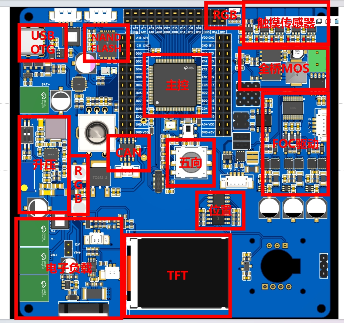
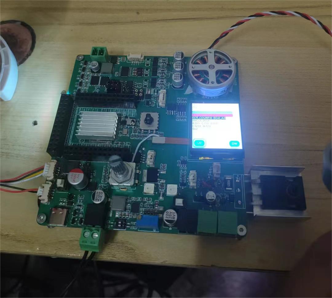
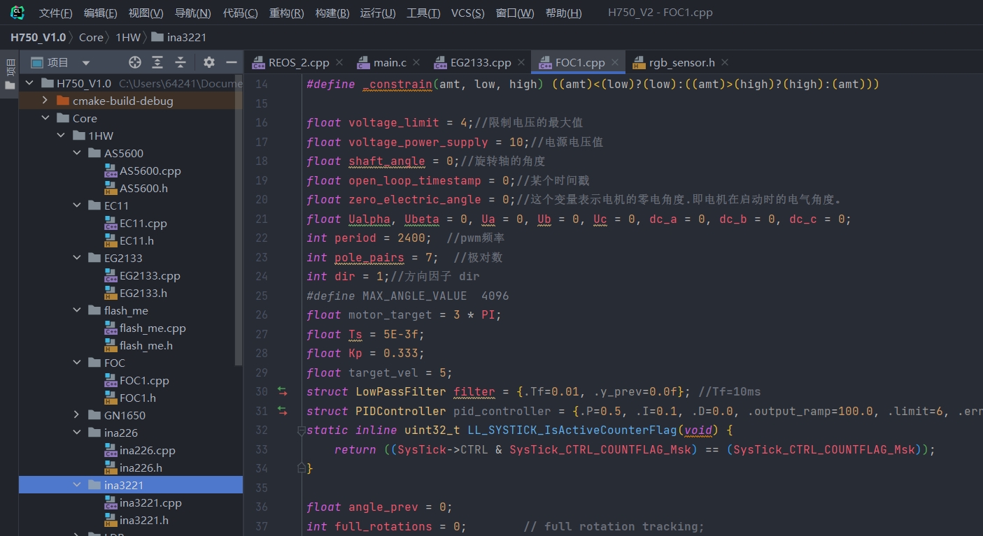
Function 1: Brushless motor drive module (function verified). A three-phase brushless motor driver based on the EG2133; using TIM1's CH1, 2, and 3 for 3PWM mode driving.

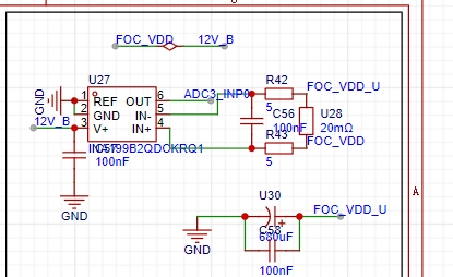
Three-phase current detection uses INA199 A2, 100x amplification, high-side current sampling (function verified).
The position sensor uses an AS5600 module (function verified )
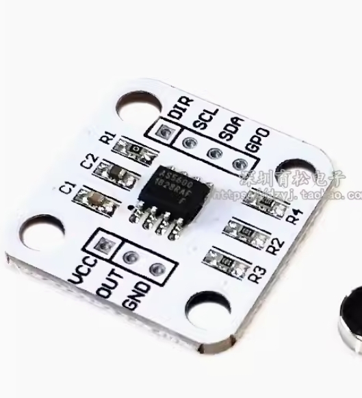
. Updated 2024.6.30: Onboard touch sensor verification, onboard AS5600 position sensor verification, onboard EC11 rotary encoder verification;
learning of 3 interactive control methods for embedded development boards;
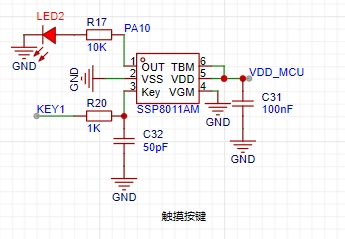
5-channel touch sensor (function verified).
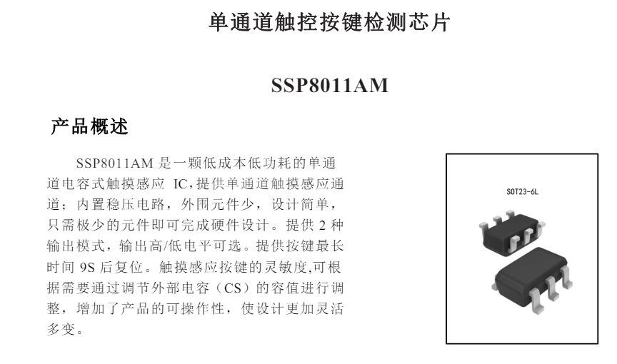
The touch chip uses 5 single-channel sensors, 4 of which are set as synchronous outputs and 1 as a latched output.
PS: A video verifying the use of the touch buttons is attached.
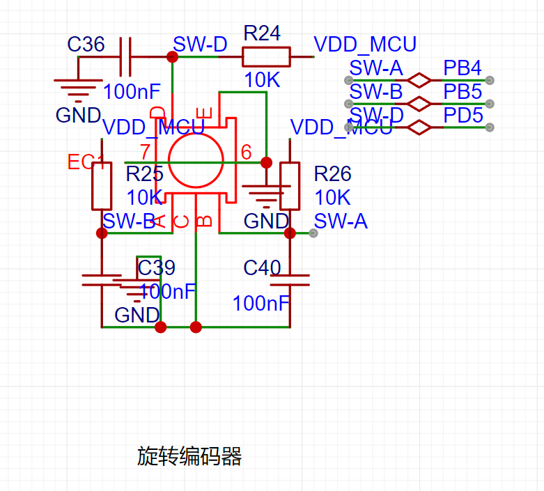
The EC11 rotary encoder (verified)
is connected to the encoder interface of the STM32 TIM3; it has external pull-up and capacitor filtering.
a01cb8036455a43472387ea7195157c9.mp4
Touch buttons, position sensor, EC11 function demonstration video.mp4
PDF_STM32H750 Multifunctional Development Board.zip
Altium_STM32H750 Multifunctional Development Board.zip
PADS_STM32H750 Multifunctional Development Board.zip
BOM_STM32H750 Multifunctional Development Board.xlsx
94008
Colored dropper
This tool mimics the eyedropper tool in Photoshop to read RGB colors.
To save costs, different colored LEDs are used as color probes, and an oscilloscope is used as the parameter display device.
I. Project Requirements:
There was a need to observe the color changes of RGB LEDs using an oscilloscope.
A quick online search revealed that the cheapest options were mostly I2C modules.
Thinking about it, since I already had an oscilloscope, why not read the data through waveforms?
Further searching for sensors revealed almost none with analog output.
In principle, it involves a photoresistor with different filters. I remembered that LEDs also generate electricity, and the voltage is proportional to the brightness. So, do different colored LEDs have different colored filters?
The principle seemed feasible, so I started testing.
II. LED Testing:
Using a WS2812 tuned to white light, the voltage of different colored LEDs under direct illumination was measured, and the results are shown in the table below.
Color Sensor |
Red LED |
Emerald Green LED
| Blue LED
| Yellow LED |
Red (FF0000) |
1150mV
| 3mV
|
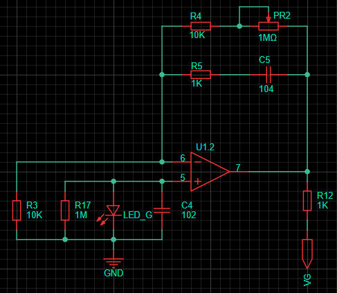
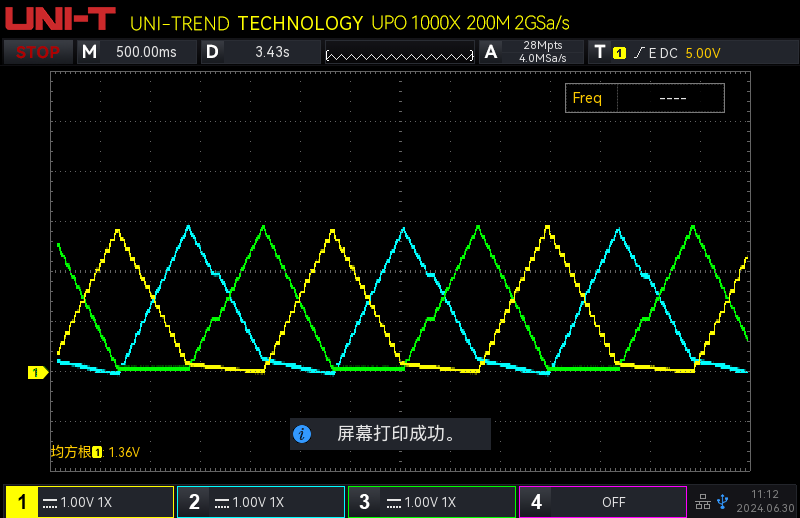
0mV | 7mV | Green ( 00FF00) | 103mV | 216mV | 0mV | 1364mV | Blue (0000FF) | 15mV | 980mV | 431mV | 172mV | Yellow (FFFF00) | 1130mV | 206mV | 0mV | 1376mV | Cyan (00FFFF) | 120mV | 1024mV | 431mV | 1397mV | Violet (FF00FF) | 1100mV | 824mV | 431mV | 183mV | White (FFFFFF) | 1100mV | 983mV The conclusions are as follows: 426mV 1402mV. The light filtering effect of some LEDs is unsatisfactory. For example, the green LED's filtering of the green wavelength of the WS2812 is not as good as that of the yellow LED . The peak voltage is inconsistent, requiring different gains for each channel . Sunlight wavelengths are more diverse, and the voltage is higher than shown in the table. Because the sun's wavelength is not constant, it is not listed separately. III. Circuit Principle : The circuit is relatively simple, consisting of an adjustable gain non-inverting amplifier circuit with different low-pass filters added to remove power frequency interference. The parameters were determined after testing. The power supply uses a lithium battery. Since I also have an adjustable power supply and a multimeter on my desk, the lithium battery charging circuit and voltage measurement circuit are omitted. This circuit is specifically designed for measuring RGB on the test bench. IV. Functional Demonstration: This is the waveform of my keyboard's RGB lighting effects. The linearity is good. The stepped effect is due to my algorithm. Channels 1-3 correspond to RGB. It can be seen that the red channel is slightly affected by green, and the green channel is affected by blue. The blue channel is the best. This matches the measurement results above. Don't be fooled by the oscilloscope's specifications. This oscilloscope is playing word games. It has two dual-channel ADCs, and the sampling rate refers to the sum of the sampling rates of the two ADCs, which I can accept. However, its bandwidth is also the sum of two 100M bandwidths.
PDF_Beggar Color Dropper.zip
Altium_Poor Color Dropper.zip
PADS_Poor Color Dropper.zip
BOM_BaiCaiColoredEyedropper.xlsx
94009
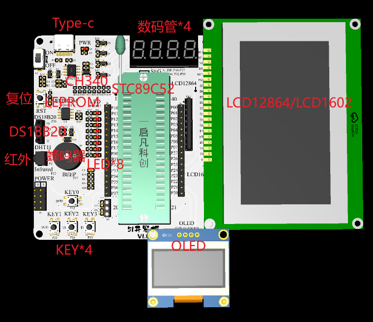
51 microcontroller one-click automatic download without power failure and restart
The 51 development board supports one-click automatic download without power interruption, has simplified peripherals, meets the learning requirements of beginners, and features clear and concise silkscreen markings. You deserve to have one.
Supported functions include:
8-digit LED display, 4-digit digital tube, 4 buttons, serial communication, buzzer, LCD1602/LCD12864, OLED, EEPROM, infrared, and DS18B20/DHT11.
Except for the socket, all components use surface-mount materials, and the resistors and capacitors are in 0603 packages (preferably packaged in a modular fashion). The attached file contains simple LED test code (there's plenty of open-source code online, so I won't elaborate).


eg0_LED.7z
PDF_51 Microcontroller One-Click Automatic Download without Power Off and Restart.zip
Altium_51 microcontroller one-click automatic download without power failure and restart.zip
PADS_51 microcontroller one-click automatic download without power failure and restart.zip
BOM_51 microcontroller one-click automatic download without power failure and restart.xlsx
94010
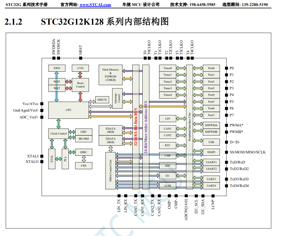
STC32G12K128 core board
STC32G12K128 core board
I. Chip Introduction
II. Project Overview
Status: Verified and working properly
Note: Further optimization is needed; LED and display screen will be added later.
III. Technical Documents:
STC32G Series Microcontroller Technical Reference Manual
PDF_STC32G12K128 core board.zip
Altium_STC32G12K128 core board.zip
PADS_STC32G12K128 core board.zip
BOM_STC32G12K128 Core Board.xlsx
94011
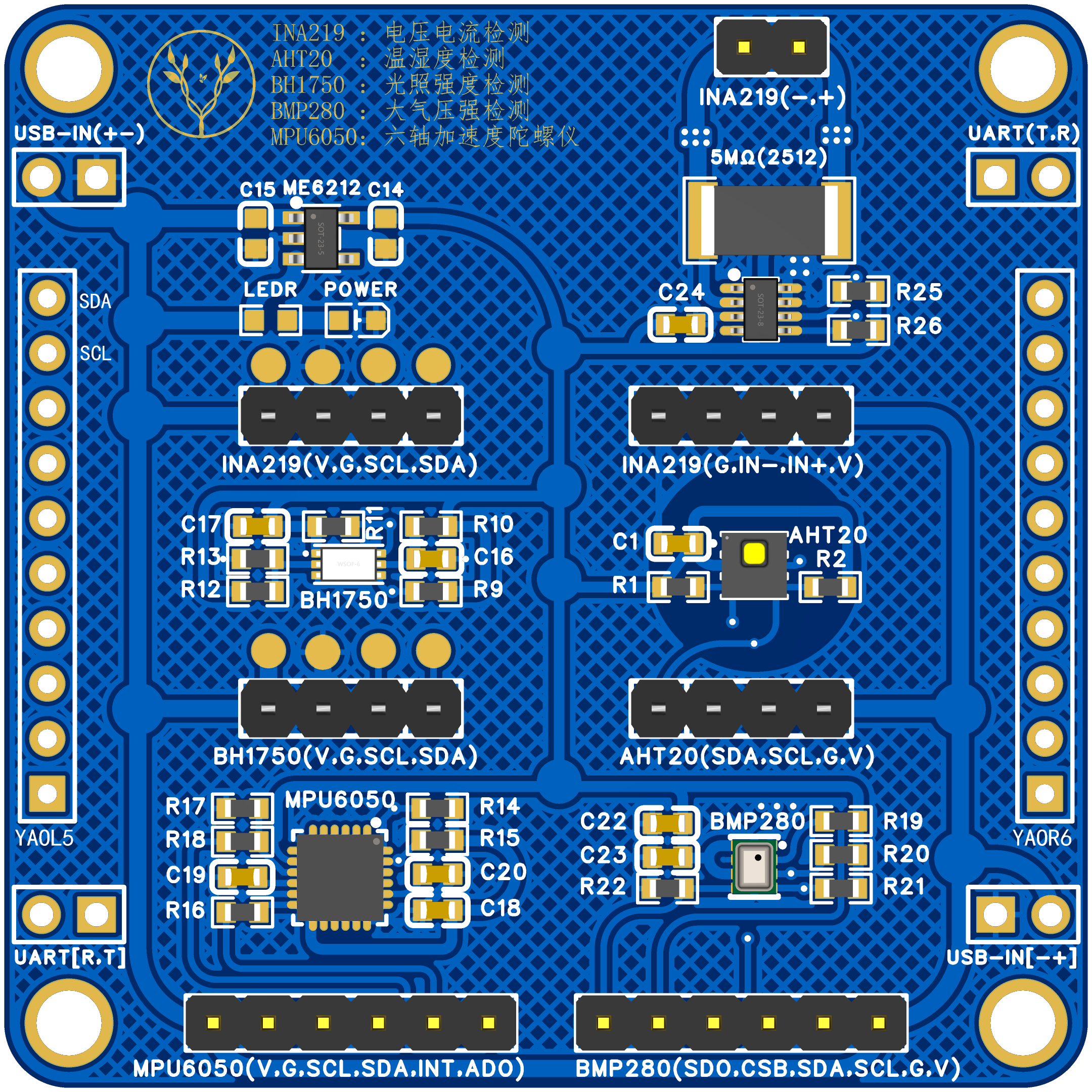
[YAO] Five-Sensor Board (Power/Light/Temperature/Humidity/Gyroscope/Atmospheric Pressure)
A sensor integrating five IIC communication methods shares a single IIC channel.
I. Purpose:
To test several sensor chips, prototyping them one by one would be a waste of resources (for environmental reasons), so I organized them and drew all the IIC communication chips on one board (IIC can support multiple devices simultaneously).
II. Chips Used
(Chip datasheets are recommended to be found on "Semiconductor X" or "X" websites; I'm too lazy to list them here):
1. LDO Power Supply: ME6212C33
2. Power Detection: INA219
3. Light Detection: BH1750
4. Temperature and Humidity Detection: AHT20
5. Six-Axis Gyroscope: MPU6050
6. Atmospheric Pressure Detection: BMP280
III. Board Description:
1. Size: 50*50cm, double-layer board
2. Each chip on the board has its IIC SDA and SCL pulled up (at the 4.7K resistor position). Normally, only one pair needs to be soldered; however, since not all chips need to be soldered, this step was left as is.
3. I've kept all the empty pin headers on the board for use with other boards (wiring is too troublesome). Unnecessary pin headers on these boards can be removed.
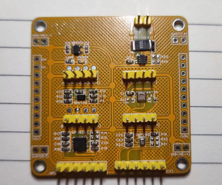
IV. Image Display
1. PCB 3D Drawing (Front and Back
) 2. Actual Component Image
V. Project Description
Design: Yao
Time: 20240701
PDF_[YAO] Five Sensor Board (Power-Light-Temperature-Humidity-Gyroscope-Atmospheric Pressure).zip
Altium_[YAO] Five Sensor Board (Power, Illumination, Temperature and Humidity, Gyroscope, Atmospheric Pressure).zip
PADS_[YAO] Five Sensor Board (Power, Illumination, Temperature and Humidity, Gyroscope, Atmospheric Pressure).zip
BOM_[YAO] Five Sensor Board (Power, Illumination, Temperature and Humidity, Gyroscope, Atmospheric Pressure).xlsx
94014
EDA version of Taishanpai active cooling 3D shell design
Among the many Taishanpai (泰山派) casings, the only one missing is the Taishanpai active cooling casing with a 3D active cooling design. Therefore, a simple and unadorned casing with an attached active cooling fan was designed, and mounting holes for an external antenna were provided. Although somewhat rudimentary (no patterns), it is sufficient and prioritizes practicality.
Brief Description:
Among the many Taishanpai shells available, the only one missing is the Taishanpai active cooling shell design. Therefore, a simple shell with an attached active cooling fan was designed, and mounting holes for an external antenna are provided. Although somewhat rudimentary (no patterns), it's sufficient and prioritizes practicality. This is the Licheng EDA version; I will also create a SolidWorks 2022 version later, which is currently being printed. Once its reliability is verified, it will be open-sourced.
Physical Demonstration: Top View
, Rear
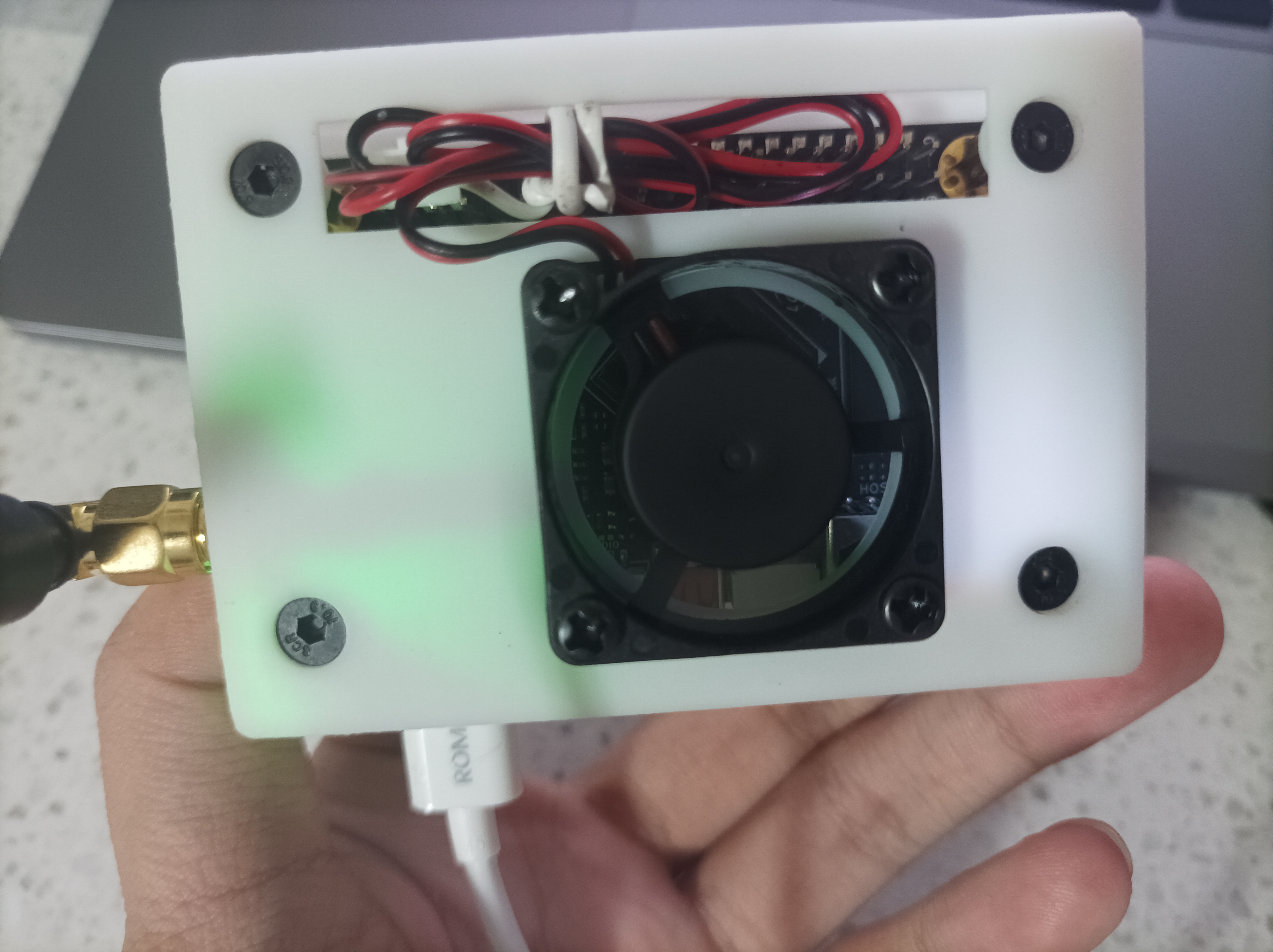
View,

Bottom View
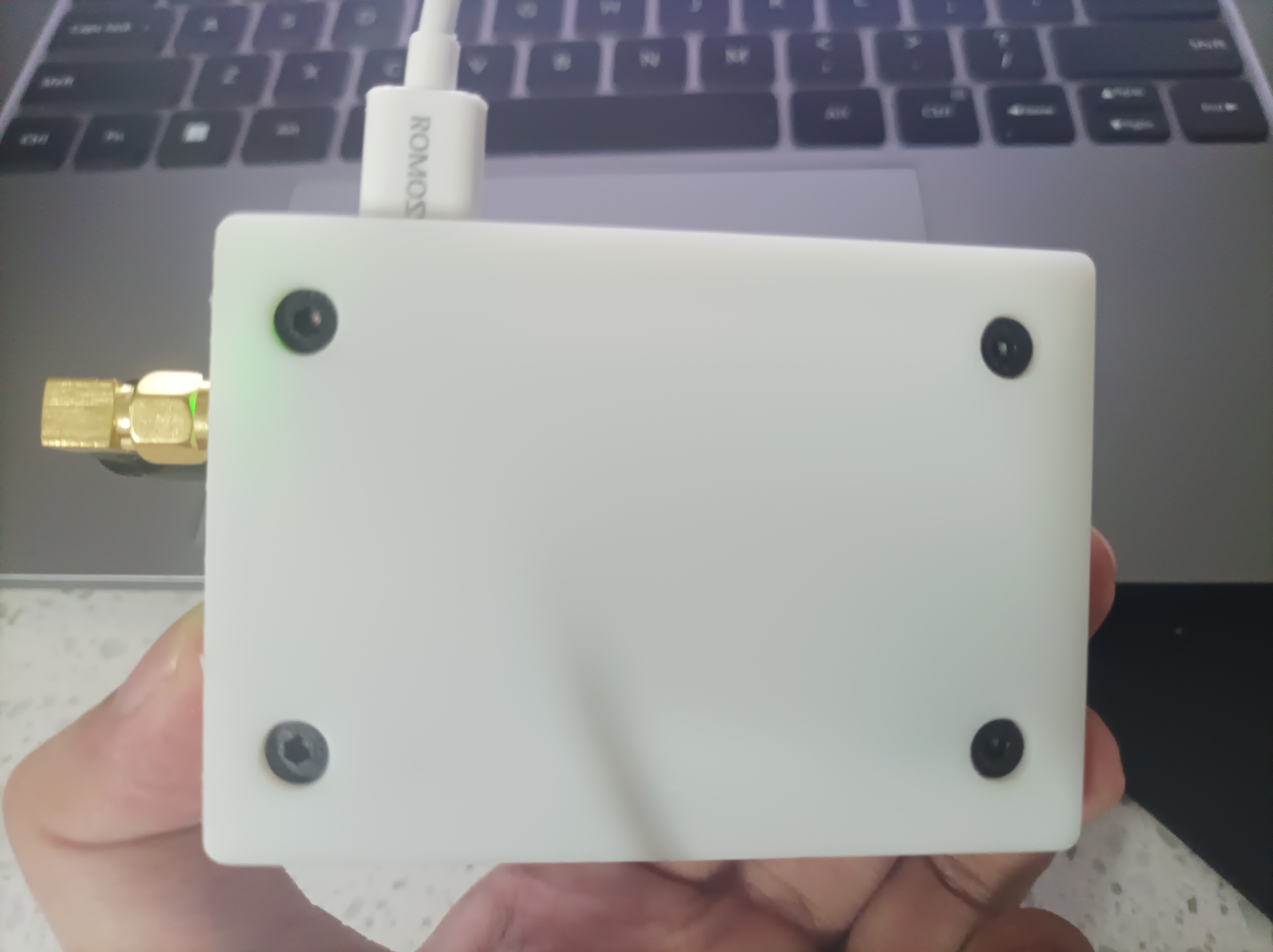
, Right View
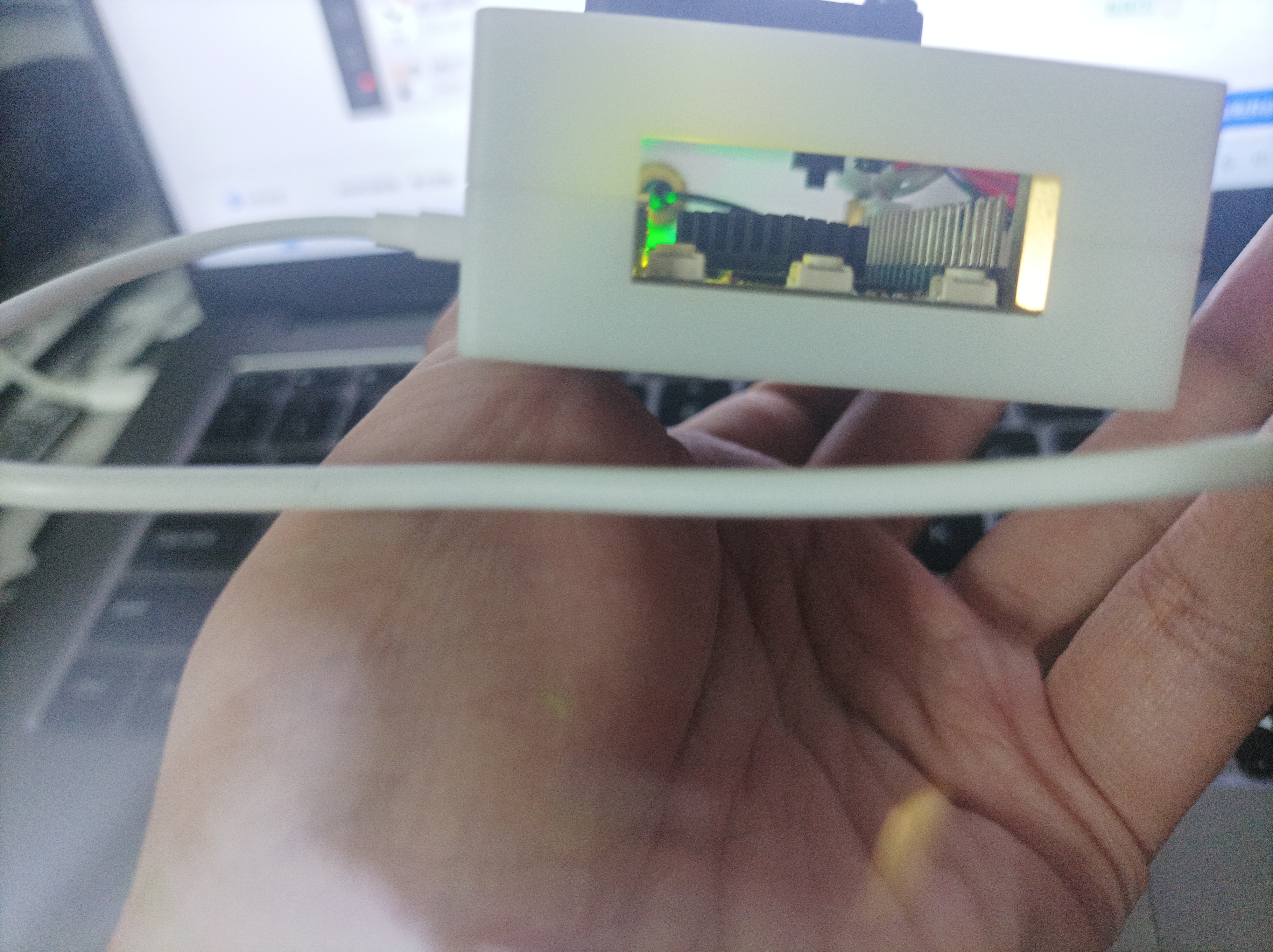
, Front View

, Left View

, 3D Shell Model

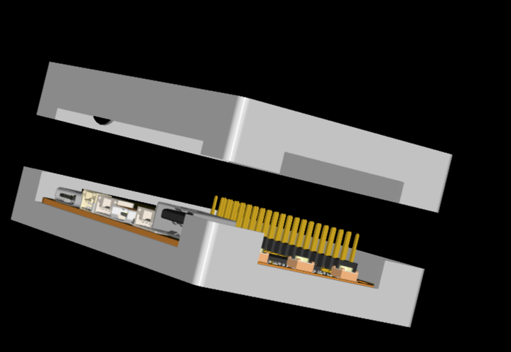
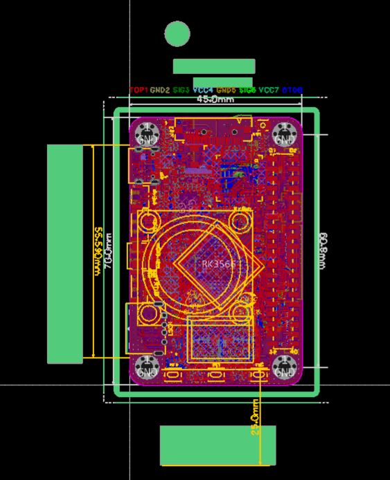
, EDA Internal Pattern
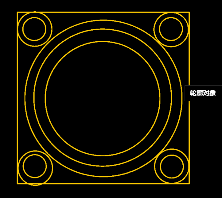
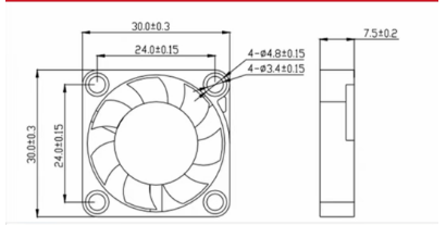
, External Fan Outline (30x30x7.5) .
Demo Video:
The demo video can be downloaded and previewed in the attachment.
Consumables List:
To accommodate antenna installation, the height of the top shell of this Taishanpai shell has been increased by 12mm, bringing the total shell height to 24mm. 9000R white sanding - coarse sanding plus 5 shipping and printing costs total 14.3 yuan (excluding the following consumables).
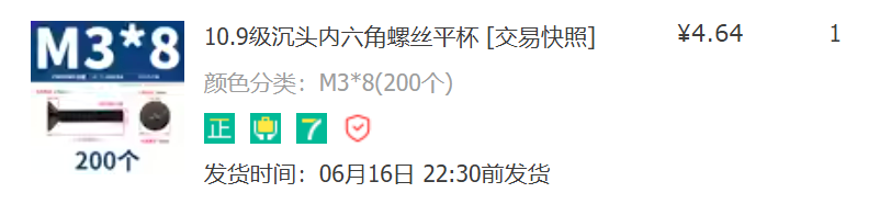
Screws: M3 8mm (casing mounting)
, M3 12mm (small fan mounting)
, M3 nuts
, M3 studs (casing mounting)
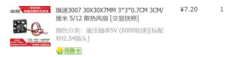
, 3cm 5V small fan,
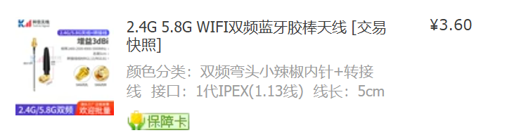
IPEX 1st generation
antenna consumables detailed introduction.
Screws
: Casing mounting screws:
M3 8mm screws
(shop link, you can also choose your own, many alternatives are available).

Fan mounting screws:
M3 12mm screws or M3 14mm screws are fine; here I provide a picture and link for M3 14mm screws
(shop link, you can also choose your own, many alternatives are available).
Nuts :
M3 nuts
for installation
(shop link, you can also choose your own, many alternatives are available). Studs:
M3 studs (12mm)
for casing mounting support
(shop link, you can also choose your own, many alternatives are available) .

Additional fan:
3cm 5V small fan (30x30x7.5).
Additional fan:
(shop link, you can also choose your own, many alternatives are available, but it must be a 3cm 5V small fan). The 30x30x7.5)
fan is easy to install; the 5V connection is just right. (Link to IPEX antenna store

for the first generation antenna - or you can choose your own; many alternatives are available.) Regarding interface and length considerations, I will provide the following files: You can directly access the upper and lower shell files for 3D printing – EDA upper shell.stl, EDA lower shell.stl – and modify the Taishanpai 3D file (you can customize these based on them). You can also open the file in EDA – tsp_3D.epro. Finally, this is the EDA version of the 3D shell. I will draw another one in SolidWorks 2022 later, modifying some details. Stay tuned; after verifying reliability, it will still be open-sourced.

Demo video.mp4
Left view.jpg
Front view.jpg
Right view.jpg
Bottom view.jpg
Back view.jpg
Top view.jpg
EDA shell.stl
EDA shell.stl
tsp_3D.epro
PDF_EDA version of the Taishanpai active cooling 3D shell drawing.zip
Altium_EDA version of the Taishanpai active cooling 3D shell design.zip
PADS_EDA version of the Taishanpai active cooling 3D shell design.zip
BOM_EDA version of the Taishanpai active cooling 3D shell design.xlsx
94016
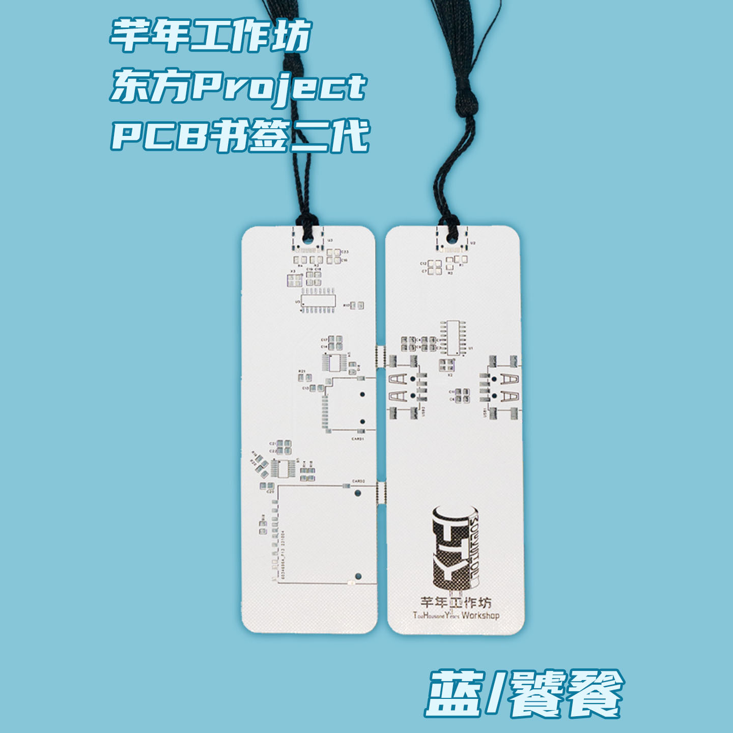
PCB Bookmark 2nd Generation (USB-HUB + Card Reader)
PCB bookmarker/USB hub/card reader based on SL2.1A and GL823K-HCY04.
This is a PCB bookmark/USB-HUB + card reader based on SL2.1A and GL823K-HCY04.
The USB-HUB only has two ports mainly for aesthetic reasons; the punched holes in the USB-A female connector are a bit obtrusive, since most people use it as a bookmark. It could be expanded to have four ports.
PDF_PCB Bookmarks 2nd Generation (USB-HUB + Card Reader).zip
Altium_PCB Bookmarks 2nd Generation (USB-HUB + Card Reader).zip
PADS_PCB Bookmarks 2nd Generation (USB-HUB + Card Reader).zip
BOM_PCB Bookmarks 2nd Generation (USB-HUB + Card Reader).xlsx
94017
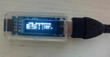
USB triaxial magnetic field sensor electronic compass
The 0.91-inch OLED screen displays the direction and angle of the three-axis magnetic field in real time. It can be used simply by plugging in a 5V USB power supply. A download port is reserved for easy modification and download of the microcontroller program later.
LCSC EDA Professional Edition design schematic and PCB layout;
USB powered, it displays the three-axis magnetic field direction angle on a 0.91" OLED screen upon plugging in;
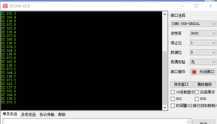
supports serial communication, with 9600, N, 8, 1 communication data transmitted as plaintext strings for easy reading and processing by the host computer
; the host computer for displaying the three-axis magnetic field direction data developed using LabVIEW programming;

the data format displayed by the serial port assistant;
a reserved download port for subsequent modification and download of the microcontroller program, using STC8G1K08A as the microcontroller master and CH340N as the USB communication chip.
Welcome to leave comments and exchange ideas!
LabVIEW three-axis magnetic field sensor monitoring system host computer.vi
USB three-axis magnetic field lower-level microcontroller uVision Keil source code.zip
PDF_USB Triaxial Magnetic Field Sensor Electronic Compass.zip
Altium_USB Triaxial Magnetic Field Sensor Electronic Compass.zip
PADS_USB Triaxial Magnetic Field Sensor Electronic Compass.zip
BOM_USB Triaxial Magnetic Field Sensor Electronic Compass.xlsx
94018
electronic


 京公网安备 11010802033920号

 218-FREQ3-BBD00010


