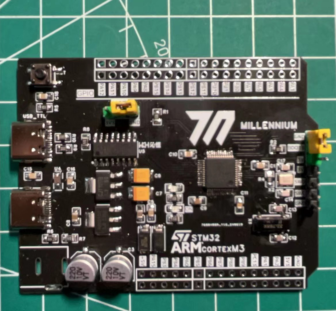
 After soldering
  , connect the USB_1 port with a data cable, set BOOT0 to 1 and BOOT1 to 0. Use ST's official software STM32CubeProgrammer and Flymcu software to read chip information.
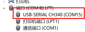

 For some reason, the two software programs read different Flash sizes; it is recommended to choose 64k.
 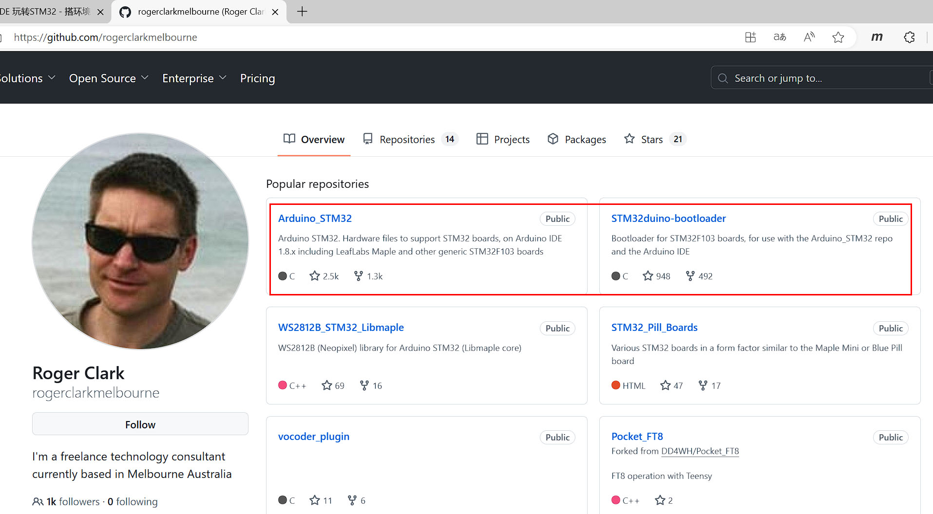 After downloading and extracting both files, connect the USB_1 port with a data cable, set BOOT0 to 1 and BOOT1 to 0. Using STM32CubeProgrammer or Flymcu software, download the generic_boot20_pc13.bin file from the binaries directory of the STM32duino-bootloader-master file to the development board (the firmware selection depends on the pins used by the LEDs on the development board; this development board uses PC13).
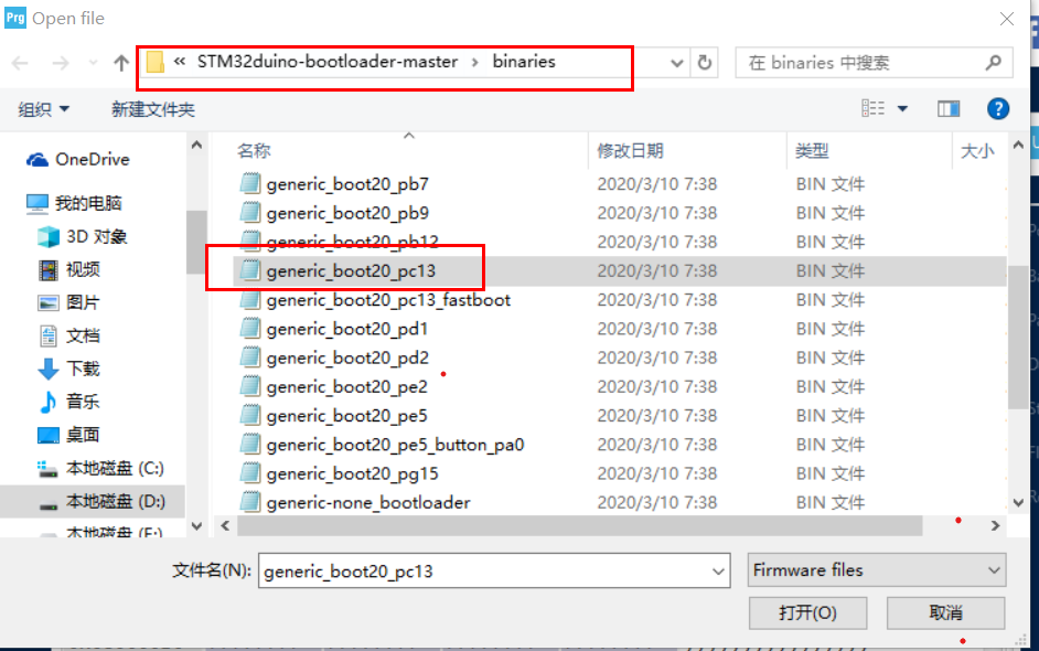
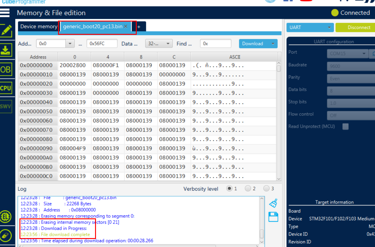 After successful firmware download, close the software, disconnect the data cable, and set BOOT0 to 0.
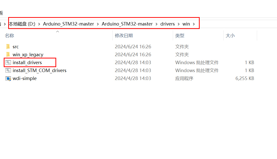
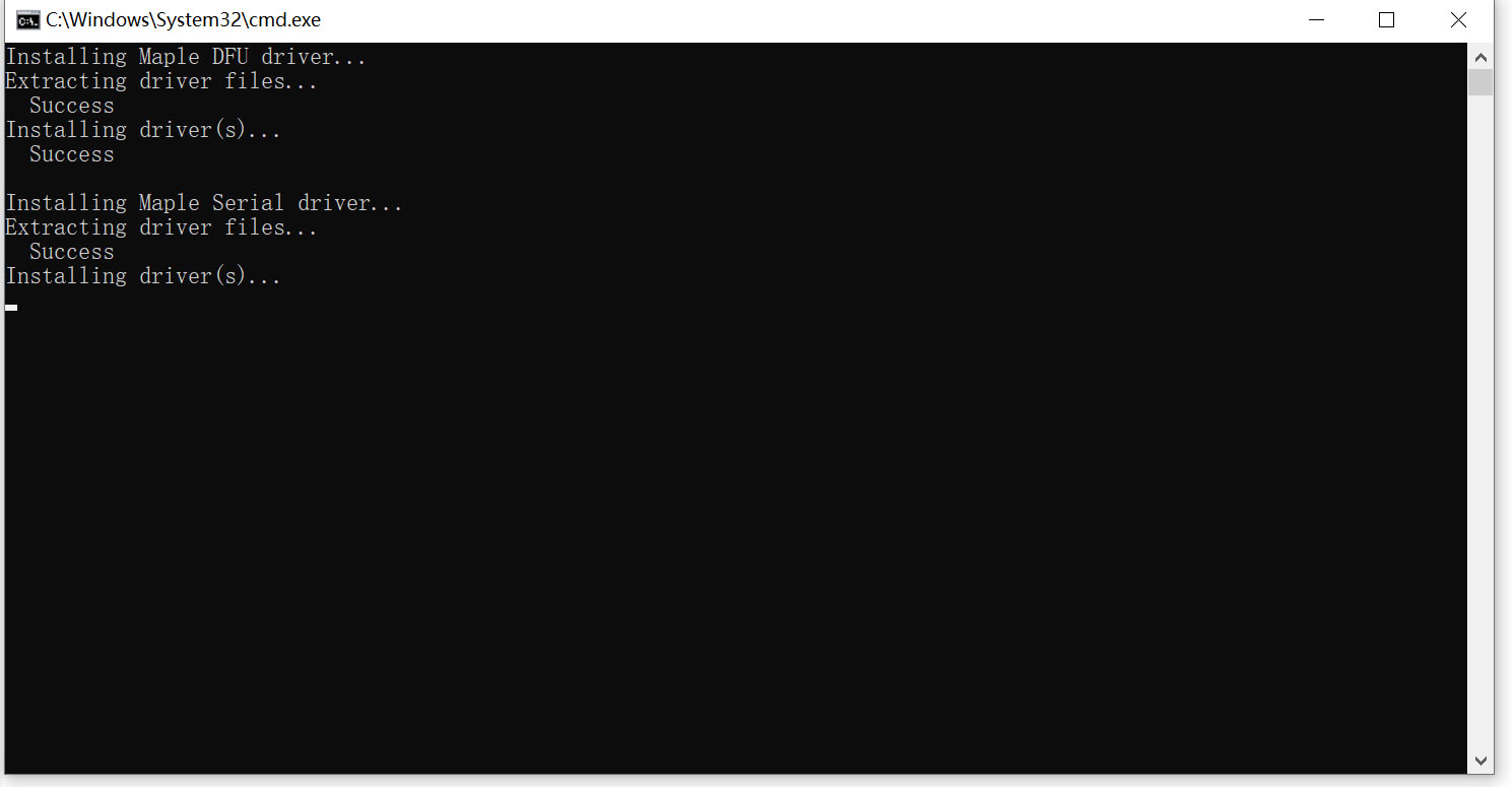 Press any key to continue. The driver installation is successful. Then connect the USB_2 port with the data cable.
 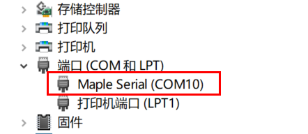 The firmware is successfully written. You can check it through the Device Manager and it will show Maple Serial (COMX).
 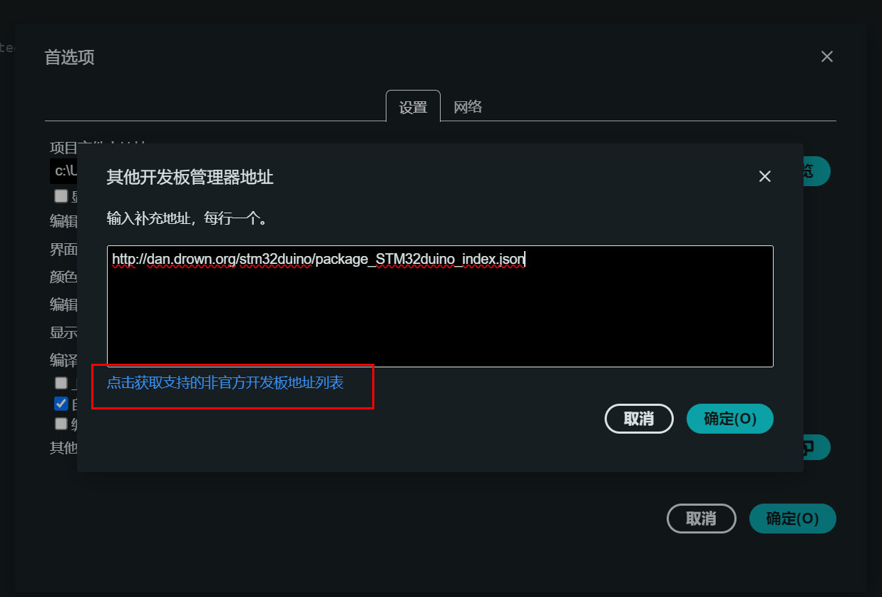 Click the blue text to find the download address of all non-official development board managers.
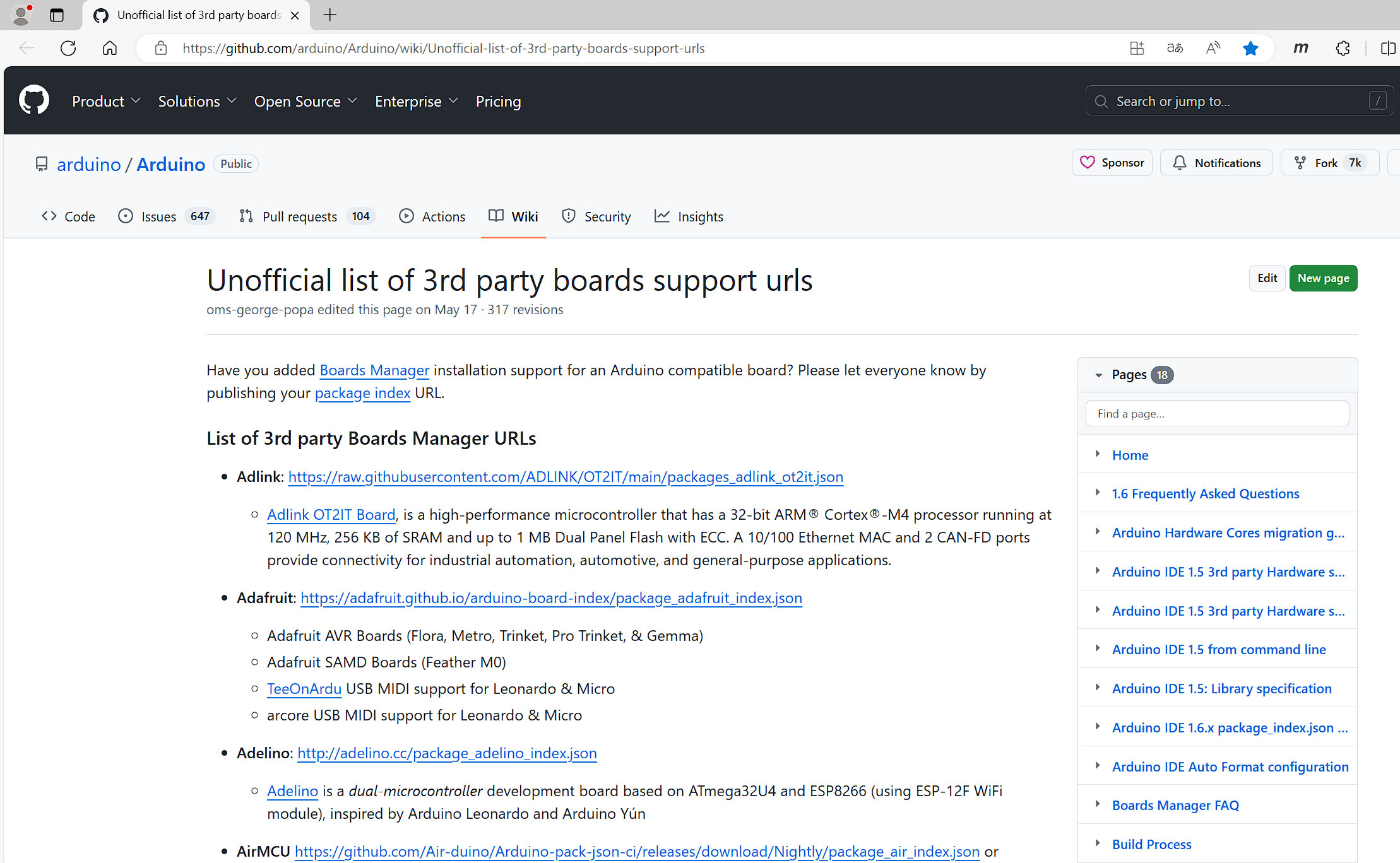
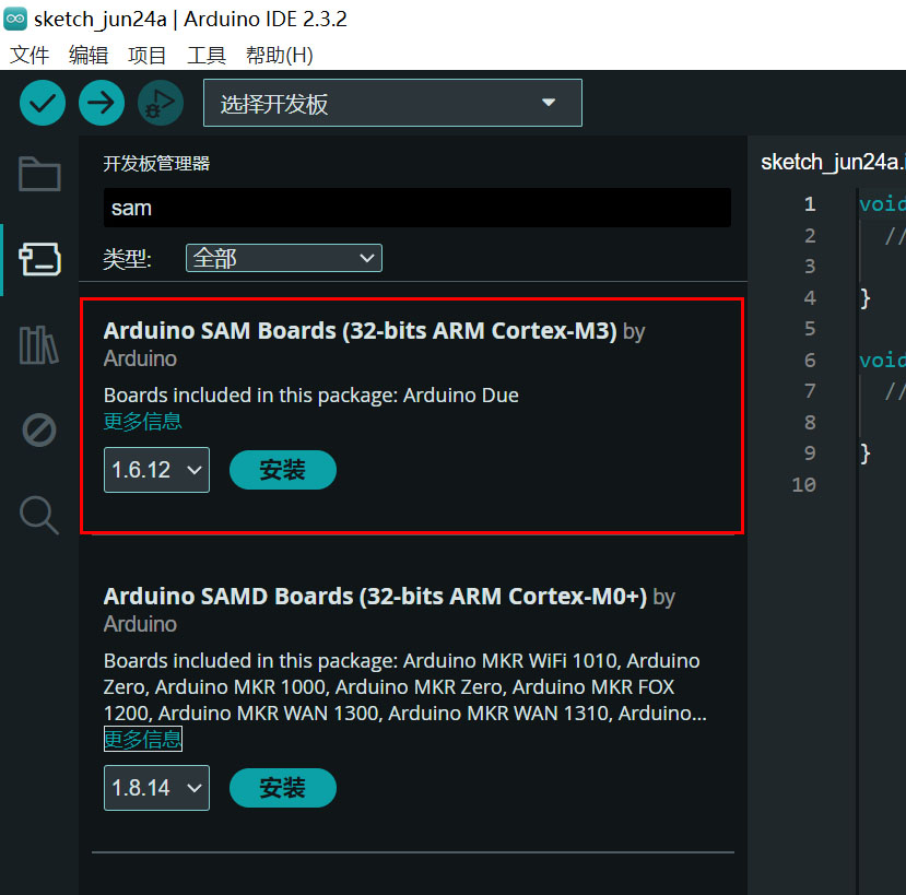
 After filling in the download address, return to the main interface and install the STM32 development board file in the development board manager.
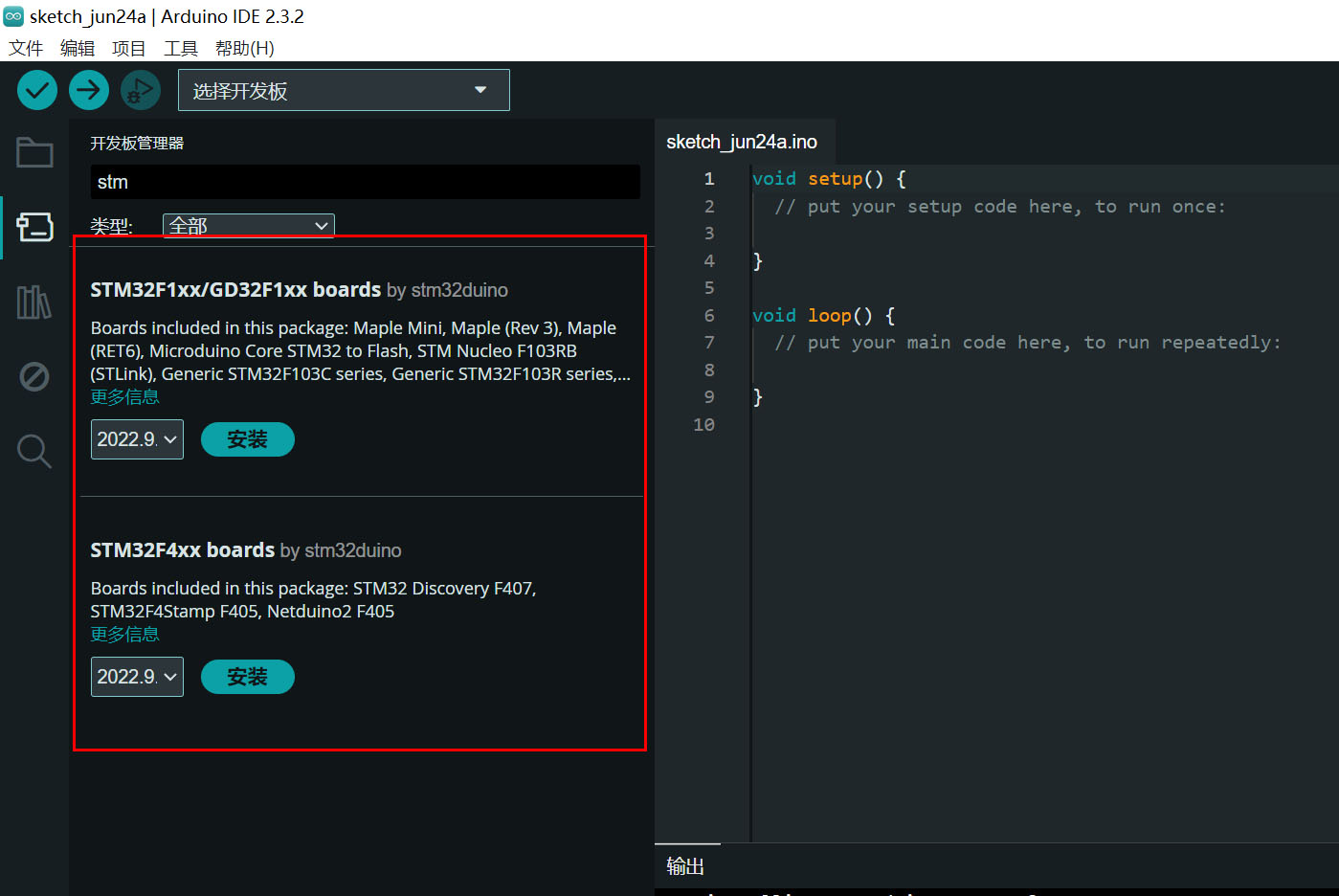
 4. Java SE 8 needs to be installed. It is recommended to install JDK 8u211 or earlier. Otherwise, errors may occur when writing programs through the IDE (search online for specific installation methods).
  select the port ,
  and select the blink example.
  The original file's PB1 needs to be changed to PC13.

All reference designs on this site are sourced from major semiconductor manufacturers or collected online for learning and research. The copyright belongs to the semiconductor manufacturer or the original author. If you believe that the reference design of this site infringes upon your relevant rights and interests, please send us a rights notice. As a neutral platform service provider, we will take measures to delete the relevant content in accordance with relevant laws after receiving the relevant notice from the rights holder. Please send relevant notifications to email: bbs_service@eeworld.com.cn.
It is your responsibility to test the circuit yourself and determine its suitability for you. EEWorld will not be liable for direct, indirect, special, incidental, consequential or punitive damages arising from any cause or anything connected to any reference design used.
Supported by EEWorld Datasheet
EEWorld
subscription
account

EEWorld
service
account

Automotive
development
community

Robot
development
community

About Us Customer Service Contact Information Datasheet Sitemap LatestNews


Room 1530, 15th Floor, Building B,
No.18 Zhongguancun Street,
Haidian District,
Beijing, Postal Code: 100190
China
Telephone: 008610 8235 0740
 京公网安备 11010802033920号

 40PC150G1A


