Project Introduction:
This is a simple FM radio. In the summers of my childhood, I loved listening to the radio in my grandfather's room. Tick-tock, tick-tock, it's 8 PM Beijing time, China National Radio, Voice of China, and then tick-tock, kids, the little loudspeaker is broadcasting.
Many years have passed, and I can't remember which sister was the host, but I cherish the memory of my grandfather and my childhood. This summer-themed activity involves making a simple radio to reminisce about my childhood. I am also an amateur radio enthusiast. Amateur radio plays a vital role in countless disaster relief efforts, and this project also pays tribute to the intelligence workers who sacrificed their lives during wartime, and to the ever-burning radio waves.
This project includes an ESP32 version, with the open-source link at https://oshwhub.com/laobainb/jian-yi-shou-yin-ji-esp32-ban.
The radio chip chosen is the DRA5807m, a new generation microcontroller-based FM stereo tuner with minimal external components. It uses I²C for communication with the microcontroller
. The audio amplifier chosen is the PAM8403, a stereo power amplifier that provides Class AB power amplifier performance with Class D amplifier effects. This requires very few external components, saving PCB space and reducing design costs.
The power management uses the IP5306, a multi-functional power management SOC integrating a boost converter, lithium battery charging management, and battery level indicator. It also requires few external components, using only one inductor to achieve buck and boost functions. The synchronous boost system provides a maximum output current of 2.4A with a conversion efficiency of up to 92%. Under no-load conditions, it automatically enters sleep mode, with the quiescent current dropping to 100uA.
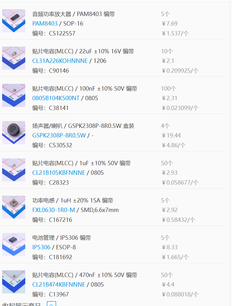
Cost Estimate (Ultimate Freebie):
JLCPCB's
electronic consumables
include main components such as battery management chips, audio power amplifier chips, and speakers, as well as peripheral components such as capacitors and resistors. The promotional coupon provided a perfect amount for the consumables, plus a free shipping coupon. Therefore, the consumables were free and shipping was included. The
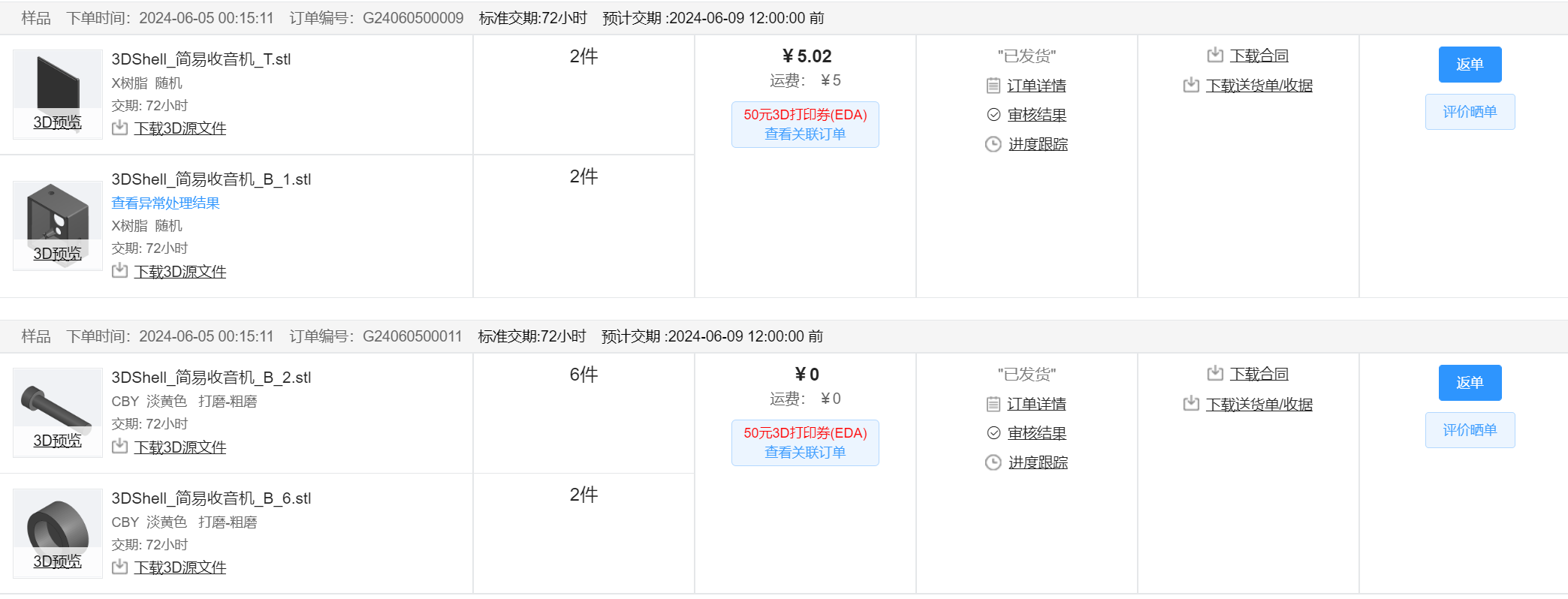
3D shell
had multiple versions, so two sets were made. The promotional coupon made it free, plus a 5 yuan shipping fee. Alipay payment incurred a 0.02 yuan handling fee. The
panel
also had a promotional coupon, was free, and was ordered together with the consumables, so shipping was also free. Furthermore, the panel supplier, Mr. Huang, was extremely conscientious and responsible. Because the gap between the speaker grille on the first version of the panel was too small, it could cause it to melt during production. Engineer Huang kept checking and following up, which was very nice.

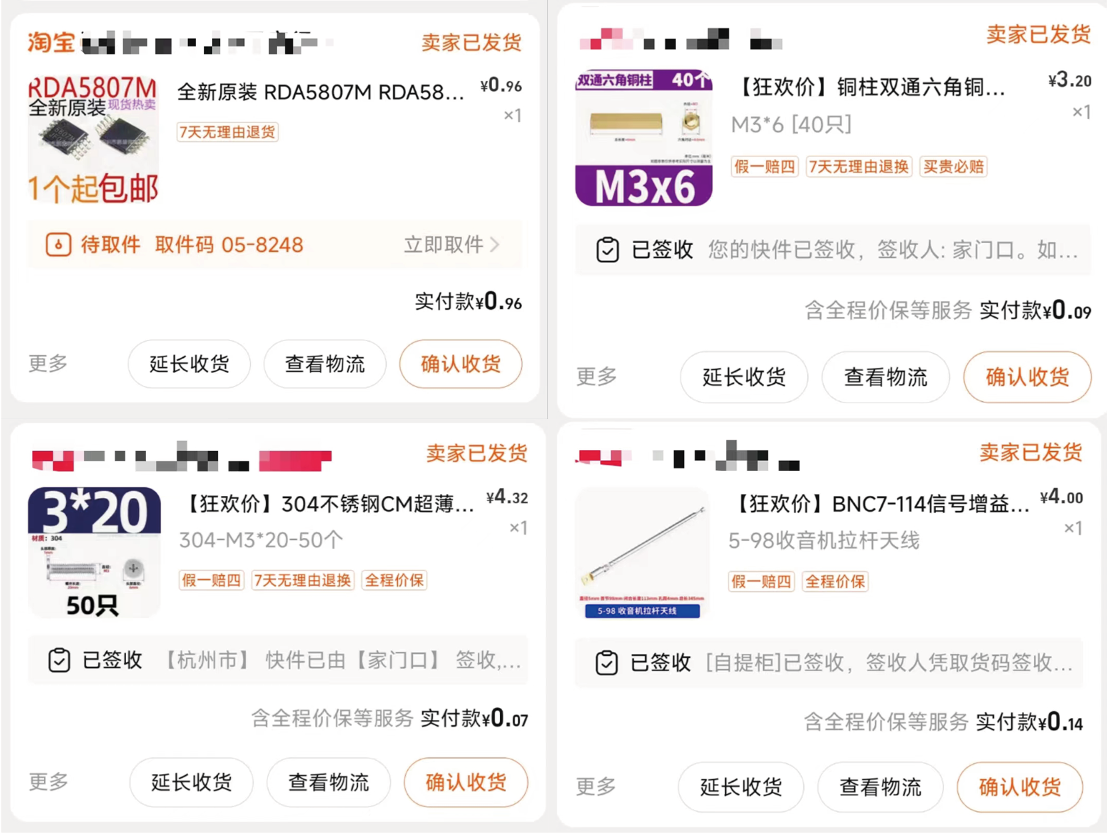
The PCB
was free, and the RDA580 (
which JLCPCB didn't have) was also included
with free shipping. Screws, nuts, and antennas were all purchased from Taobao. With various discounts, it was a great deal; I practically got a steal! Haha~~
The
basic principle of a radio is that the radio station modulates the audio signal → transmits it through the antenna → it propagates in space → it is received by the radio → it is demodulated and played through the speaker.
Modulation is
because the sound we usually hear is a low-frequency signal, but low-frequency signals have a very short propagation distance. If we want the signal to travel further, we need a higher signal, so we superimpose the sound signal (approximately several hundred Hz) onto a high-frequency signal (possibly several hundred MHz). Then, transmission occurs. Modulation methods include amplitude modulation (AM) and frequency
modulation
( FM).
FM
modulation has a constant amplitude, but the frequency changes with the low-frequency signal.
AM modulation has
a constant frequency, but the amplitude changes with the low-frequency signal.
A diagram illustrates
the sound signal
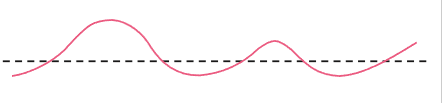
: high-frequency signal (equivalent to a carrier)

→ FM

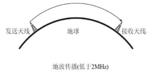
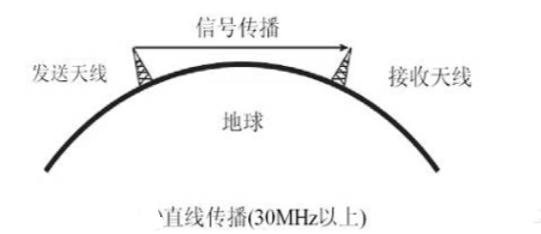
→ AM transmission. Propagation

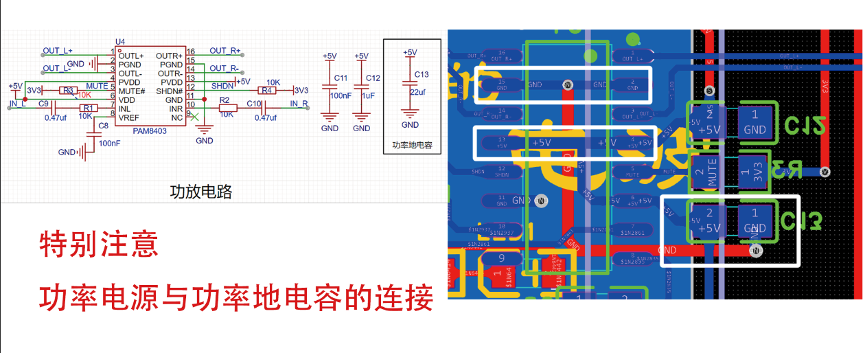
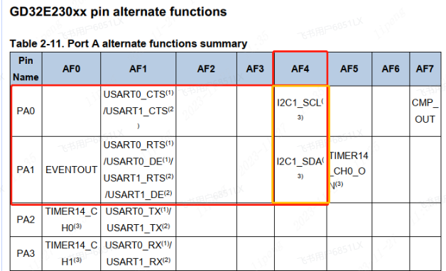
methods include skywave (radio waves reflected by the ionosphere and returning to the ground), groundwave (radio waves propagating along the Earth's surface), and spacewave (radio waves propagating in a straight line from the transmitter to the receiver), etc. Demodulation hardware explanation : RDA5807M . The RDA5807M series is a new generation of single -chip microcontroller broadcast FM stereo tuners, featuring a fully integrated synthesizer, intermediate frequency selectivity, RDS/RBDS, and MPX decoders. The tuner uses CMOS technology, supports multiple interfaces, and requires minimal external components. All of these make it ideal for portable devices. The RDA5807M series has a powerful low-IF digital audio processor, which ensures optimal sound quality under various receiving conditions. The RDA5807M series supports a frequency range from 50MHz to 115MHz. Pins 1, 3, and 8 are GND (ground). Pin 7 is for power supply; according to the datasheet, the supply voltage is 2.7V~3.3V. Use a 47uF electrolytic capacitor and a 100nF surface-mount capacitor to filter out low-frequency and high-frequency noise from the power supply, respectively. Pin 6 connects to the crystal oscillator; according to the datasheet, select a 32.768kHz capacitor and include ground in the PCB design. Avoid copper pouring in prohibited areas, and ensure that power lines are not used on any layers in the crystal oscillator area. Pins 4 and 5 are the RDA5807M's I²C communication pins, connected to the core board. Consult the datasheet to check which I²C-supported I/O ports are available. When using I²C, you can choose between automatic I²C and hardware I²C. To facilitate later development, we selected pins (PA0, PA1) with I²C multiplexing function, thus providing hardware I²C support. If we used software I²C, it would simply be used as a copper-plated I/O port. Pins 9 and 10 are audio output interfaces, each connected to the PAM8403 power amplifier chip via a 100nF coupling capacitor. The PAM8403 is an excellent audio power amplifier integrated IC. It can provide 3W of power with an efficiency exceeding 85%, and also features system shutdown and mute control functions. Its special circuit architecture enhances noise immunity and reduces RF interference. According to the chip datasheet (see attachment), pin 6 is the power supply pin, using 5V; pin 11 is ground, using 100nF and 1uF capacitors to filter out high-frequency and low-frequency noise; pins 4 and 13 are power supply pins; and pins 2 and 15 are power ground pins. Considering the low power consumption, no isolation from the analog signal was implemented. However, to prevent ground shift, a 22uF capacitor was used. This capacitor should be placed as close as possible to the power supply and power ground. (If there is a ground shift in the circuit, the original 5V voltage may not be 5V anymore, but will become another voltage. This is because the 5V voltage is relative to the GND ground line (0V). If the ground shift causes the GND ground line to rise from 0V to 1V, then the previous 5V (5V-0V=5V) voltage becomes 4V (5V-1V=4V)).


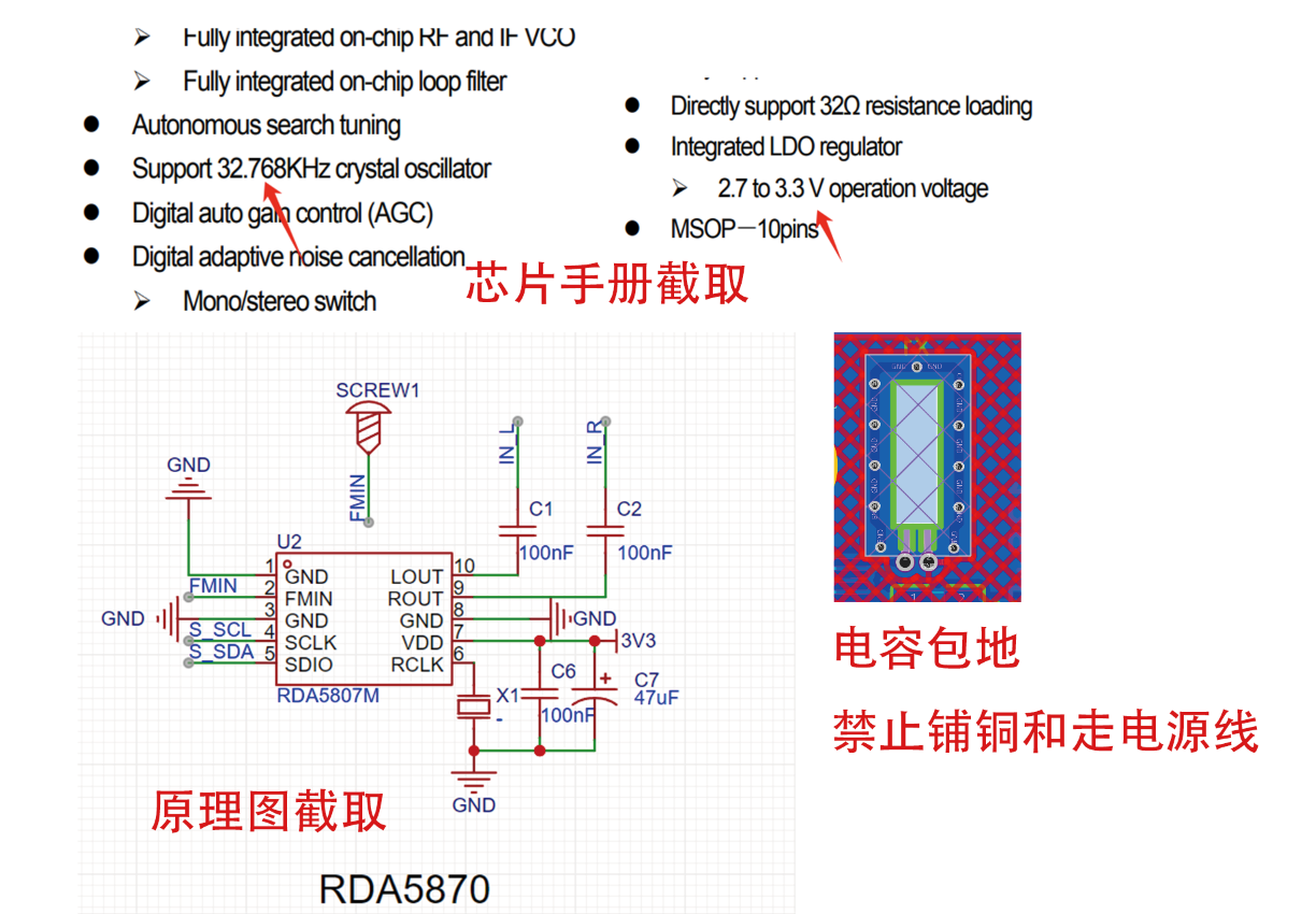
Pin 8 is the internal reference source, connected to GND via a 100nF bypass capacitor.
Pin 10 is the input for the left and right channels respectively, connected in series with a 10k~20k resistor and a 0.47uf capacitor according to the chip datasheet.
Pins 1, 3, 16, and 14 are the positive and negative terminals for the left and right channels respectively, directly connected to the speaker (speaker interface).
Pin 5 is the mute control input, active low, pulled high by a 10k pull-up resistor and connected to the microcontroller core board for later program control.
Pin 12 is the system shutdown control, active low, also pulled high by a 10k pull-up resistor and connected to the microcontroller core board for later program control.
Pin 9 is a no-go pin, left floating.
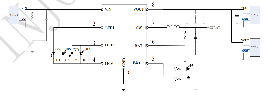
Battery management
uses IP5306 for charge/discharge management; the external circuit is simple and easy to control.
Pin 1 is the power input, connected to the Type-C input.
Pin 8 is the output, supplying power to the entire circuit
. Pins 2, 3, and 4 connect to the positive terminal of the battery. Pins 4 connect to the
power indicator LED. The RDA5807 supports I²C communication, which can be achieved using both software and hardware I²C. For code simplicity (I'm too lazy to write complex code to handle timing signals, data signals, error detection, signal conflicts, etc.), and since this is a radio, we will use hardware I²C. Referring to the chip datasheet, we will use PA0 and PA1. Define variables and crystal oscillator #ifndef __RDA5807_H // Positive and negative feedback #define ACK 0 #define NACK 1 // Boolean variable #define TRUE 1 #define FALSE 0 // Read/write flag #define READ 1 #define WRITE 0 #define ADRW 0x20 // RDA5807P write register address #define ADRR 0x21 // RDA5807P read register address /* * This radio uses the RDA5807M module, which uses a 32.168KHz crystal oscillator. If using other crystal oscillators, use different macro definitions according to the frequency */ //#define _SHARE_CRYSTAL_24MHz_ // 24MHz crystal oscillator //#define _SHARE_CRYSTAL_12MHz_ // 12MHz crystal oscillator #define _SHARE_CRYSTAL_32KHz_ // 32KHz crystal oscillator //#define _FM_STEP_50K_ //50K steps. Then, configure the I²C. Different manufacturers have different configuration methods, but the process is the same: enable the clock, configure the pin multiplexing and function of SCL and SDA, configure the IC address, and enable the response. This project is applicable to GD32, CW32, and STM32. Different main controllers have different function libraries and initialization methods, but the way to manage RDA5807 is the same. Setting the frequency void RDA5807_SetFreq(short int curFreq) { unsigned short int curChan ; curChan = RDA5807_FreqToChan(curFreq); //SetNoMute RDA5807_REGW[0] |= 1 << 7; RDA5807_REGW[2] = curChan >> 2; RDA5807_REGW[3] = (((curChan & 0x0003) << 6) | 0x10) | (RDA5807_REGW[3] & 0x0f); OperationRDAFM_2w(WRITE, &(RDA5807_REGW[0]), 4); delay_ms(50); } Read frequency unsigned short int RDA5807_RegToInt(void) { unsigned char RDA5807_REGR[10] = {0x0}; unsigned short int temp; OperationRDAFM_2w(READ, (unsigned char *)&RDA5807_REGR[0], 10); temp = RDA5807_REGR[0]; temp = ((temp << 8) | RDA5807_REGR[1]); temp = (temp & 0x03FF) * 10 + 8700; return temp; } Set mute void RDA5807_SetMute(int mute) { if(mute == TRUE){ RDA5807_REGW[0] &= ~(1<<6);//Enable bit 14 of register 02H to be 0, enable mute } else{ RDA5807_REGW[0] |= 1<<6; }
OperationRDAFM_2w(WRITE, &(RDA5807_REGW[0]), 2);
delay_ms(50); //Deadly 50 ms
}
In conclusion
, I want to say to everyone that it's over. I don't know what to say, but the sense of ritual in summarizing is still necessary. Let's pay tribute again to the never-ending radio waves. This is BG5AWB


 京公网安备 11010802033920号

 HDSP-333Y-KK100


