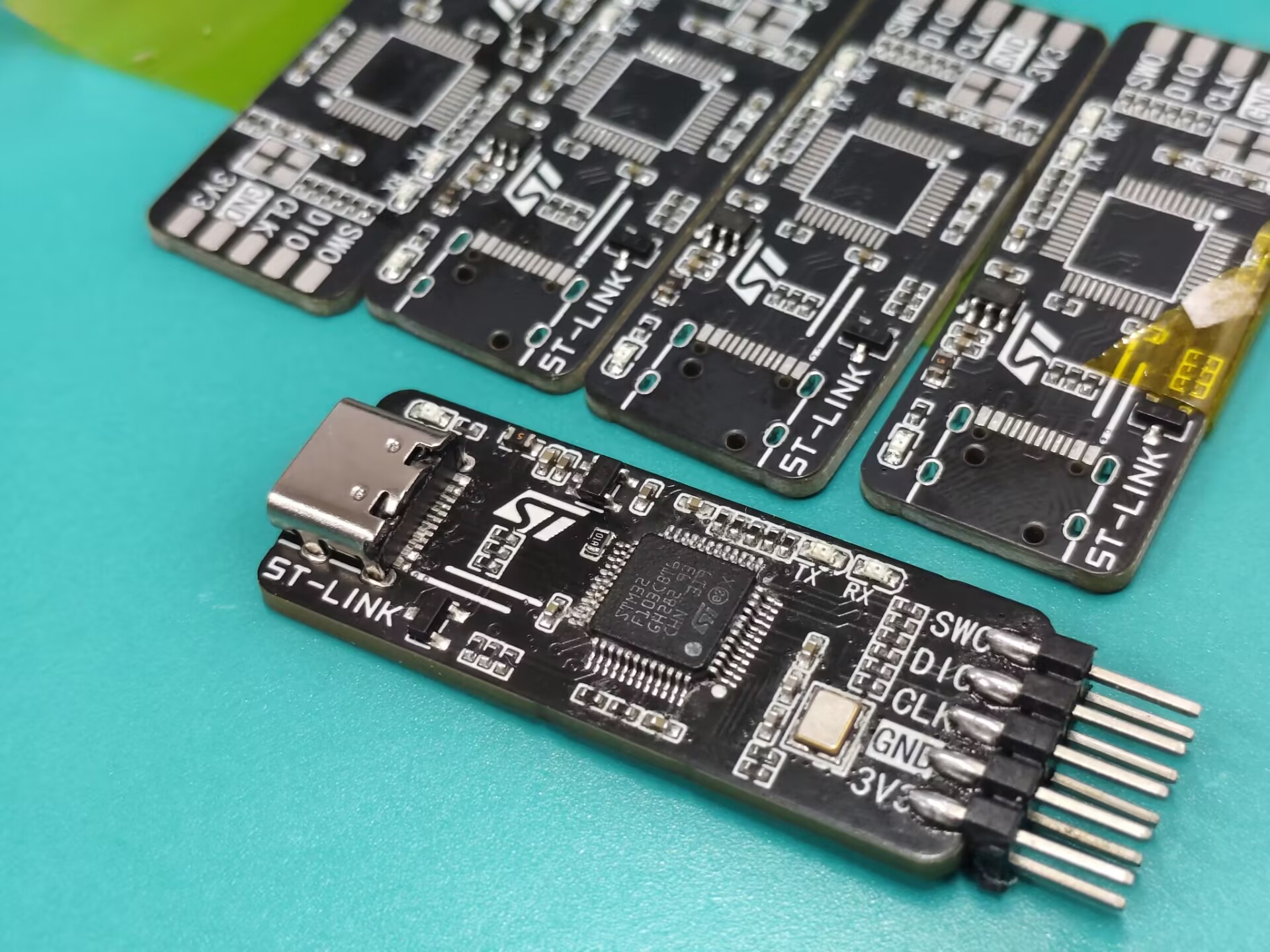
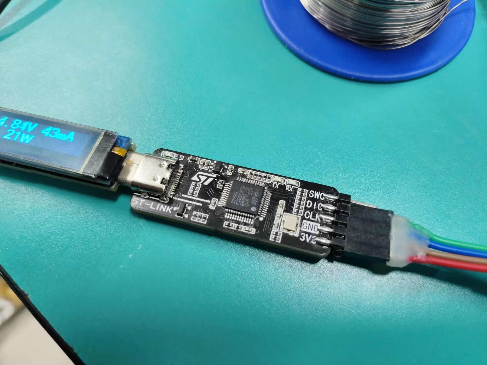
This project's circuit design is based on the official ST-LINK design, and the official schematics have been uploaded as attachments. The firmware
references Chen Zhe's open-source project: https://oshwhub.com/CYIIOT/ST_LINK-V2_1.
to support STM32 debugging, and includes a serial port and virtual USB drive for downloading. It also features connection indicator lights and a serial port indicator light.
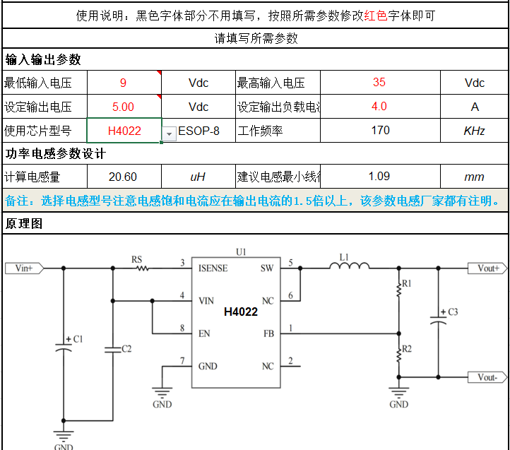
The H4022 is a high-efficiency synchronous buck DC-DC converter that provides a high voltage withstand of 40V and a high current output of 4A. It supports a wide voltage regulation from 2.5V to 24V, operates at a frequency of 170kHz, and features excellent EMI characteristics and a superior heat dissipation design with an efficiency of 94%.
The H4022 is a high-performance DC-DC synchronous buck constant voltage/constant current controller manufactured by Dongguan Huihai Semiconductor Co., Ltd. This chip integrates a 40V withstand voltage MOSFET, capable of handling input voltages up to 38V while supporting continuous output current up to 4A, ensuring its applicability in various power supply environments. The H4022's output voltage range is adjustable from 2.5V to 24V, achievable through simple voltage divider resistor adjustment, ensuring power supply flexibility. The chip employs a high-side current-mode control principle, providing fast dynamic response and high efficiency, while a fixed 170kHz switching frequency helps reduce electromagnetic interference. Furthermore, the H4022 features comprehensive protection functions including short-circuit protection, over-temperature protection, and under-voltage protection, ensuring the safe and stable operation of the power system. Optimized current sensing design and enable control functions further improve overall efficiency and ease of power management. The chip uses an ESOP-8 package and features a power heat dissipation pad on the bottom, effectively improving heat dissipation performance. The H4022 is suitable for various applications such as car chargers, lighting, portable device power supplies, and battery chargers, making it an ideal power management solution for electronic device design. It is inexpensive, with bulk pricing around 0.6 RMB.
The synchronous buck architecture offers several significant advantages in power management, making it the preferred solution for high-efficiency electronic designs. This architecture achieves high efficiency by using two switching devices simultaneously—the upper and lower transistors—as it reduces the power consumption of individual devices during conduction, thereby reducing the overall system's thermal load. Synchronous rectification technology also helps reduce output voltage ripple, providing a smoother voltage output, while enhancing load regulation to ensure stable voltage levels under varying loads. Furthermore, synchronous buck converters typically have fewer external components, simplifying the design process and helping to reduce the physical size of the solution, making them particularly suitable for portable or space-constrained applications. They can also handle a wide range of input voltages, easily integrate soft-start and various protection functions such as overcurrent, overtemperature, and undervoltage protection, thereby improving system reliability and stability. These features of the synchronous buck architecture make it particularly outstanding in applications requiring high current output, while also improving electromagnetic compatibility, making it an indispensable part of power supply solutions.
Thanks to Mr. Huang Jinyu, Sales Manager of Dongguan Huihai Semiconductor Co., Ltd., for his support. For chip procurement, please contact VX: 13924924865.
Recommendation: Avoid 4A output as the chip will overheat; the chip temperature reaches 83°C at 3A output.


1. An SS36 Schottky diode is used at the input for reverse connection protection. Its function is to protect the chip from damage if the input power is reversed. The advantage of using a diode is its low price, but the disadvantage is slightly higher power loss.

2. Four 10uF, 35V X5R MLCC capacitors are used for the input. According to the official reference calculation document, the minimum input capacitance is 47uF. Therefore, four 10uF, 35V MLCC capacitors and one 0.1uF, 50V X7R MLCC capacitor are connected in parallel. These five capacitors should be placed close to the VIN pin during PCB layout.
Notes: X7R and X5R capacitors indicate their temperature tolerance; X5R represents -55°C to +85°C, and X7R represents -55°C to +125°C.

3. Inductor selection: Using the official table, input voltage, output voltage, and current were entered. After calculation, a reference inductance of 20.6uH was chosen. However, this value is unavailable, so a 22uH inductor was selected. Shielded inductors are preferable to reduce EMI and improve stability and safety. Since a 22uH inductor was unavailable, a 47uH/3A inductor was used.
4. Output capacitor selection: Four 22uF, 25V X5R capacitors were chosen. The table references 1000uf/16V electrolytic capacitors. Due to the higher equivalent ESR of electrolytic capacitors, four 22uF capacitors and one 0.1uf MLCC capacitor were ultimately selected.

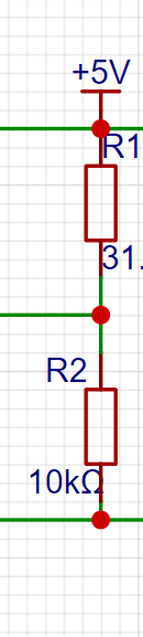
5. The feedback voltage sampling resistor uses 31.6K, and 10k±1% forms the feedback network. These two values are readily available; alternatively, values from the reference table can be used.
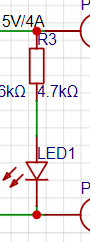
6. A red LED is included as a power indicator, and a 4.7K current-limiting resistor is used.
II. Layout Requirements
Official Layout Recommendation:
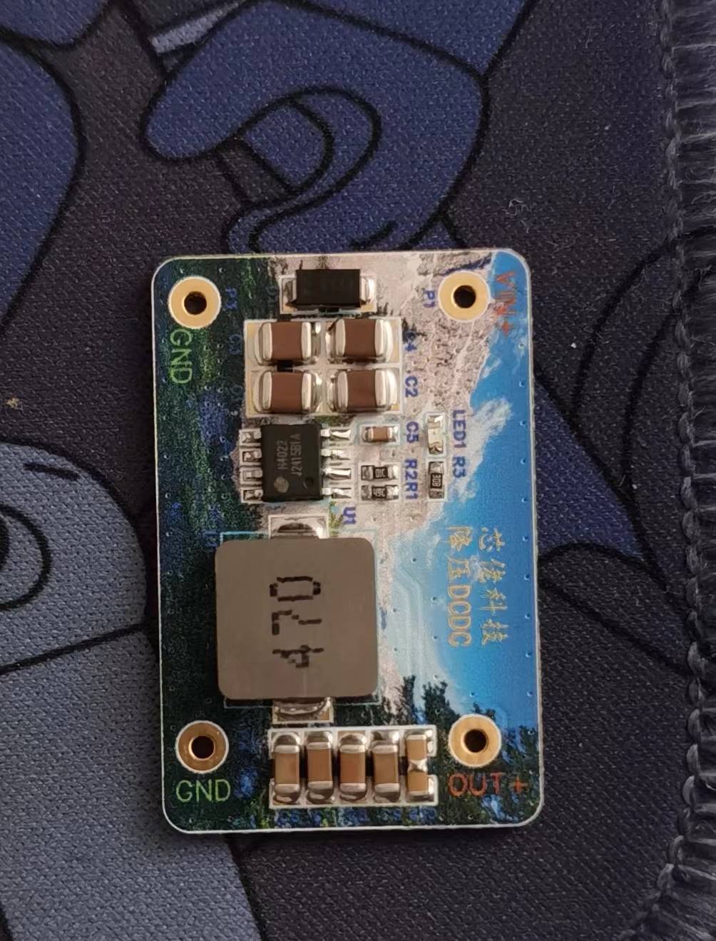
Based on the reference guidelines, the following is my personal layout; please forgive any shortcomings. This prototype uses immersion gold color silkscreen printing.

2.1 Due to the inherent ±1% error of the resistors, the measured output voltage accuracy is ±1%.

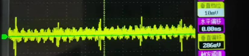
2.2 No-load ripple: Due to the limited equipment and lack of a load cell, the measured no-load ripple is 10-20mV. For chips under 1 unit, this is considered a high-performance chip.
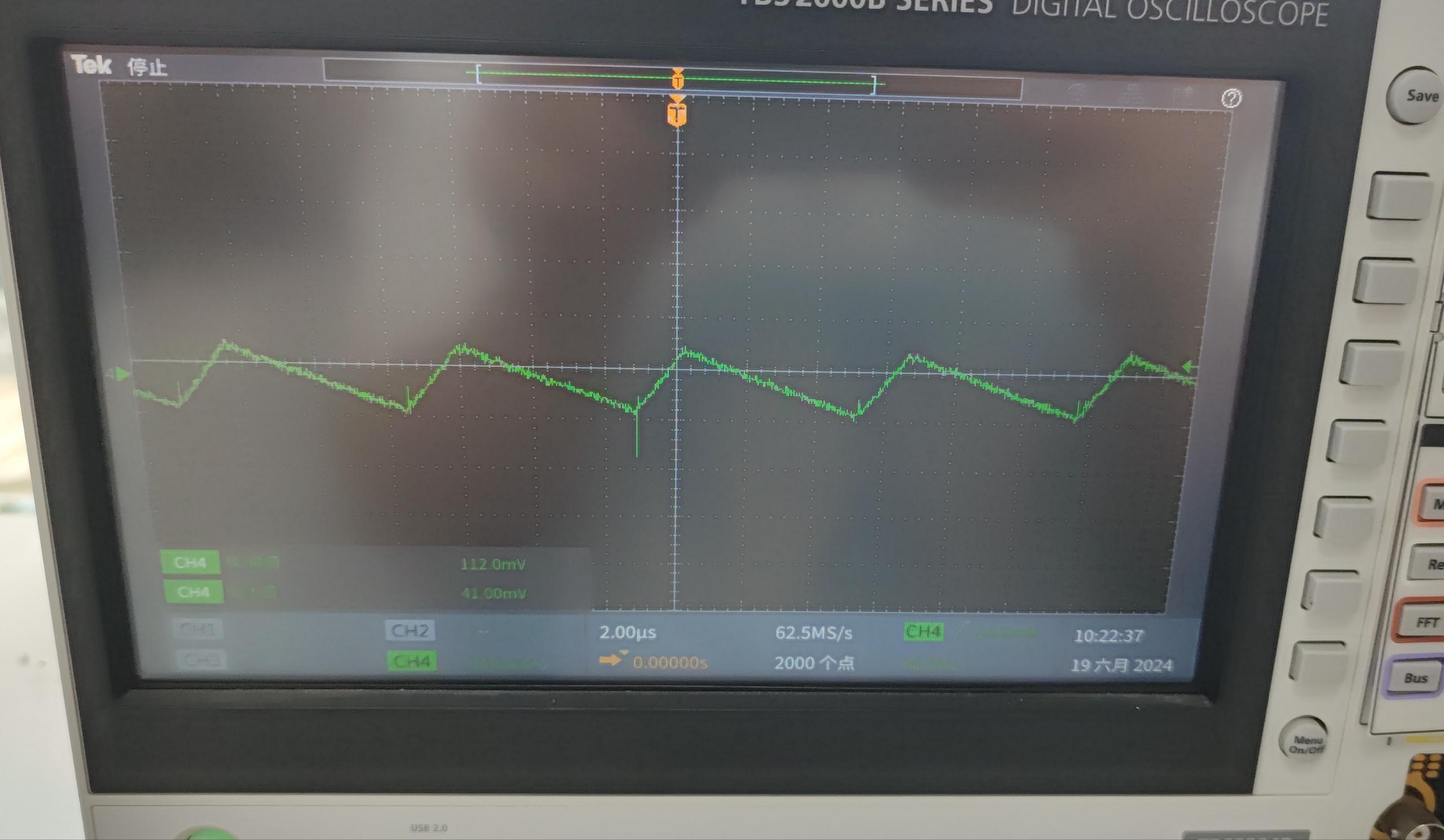
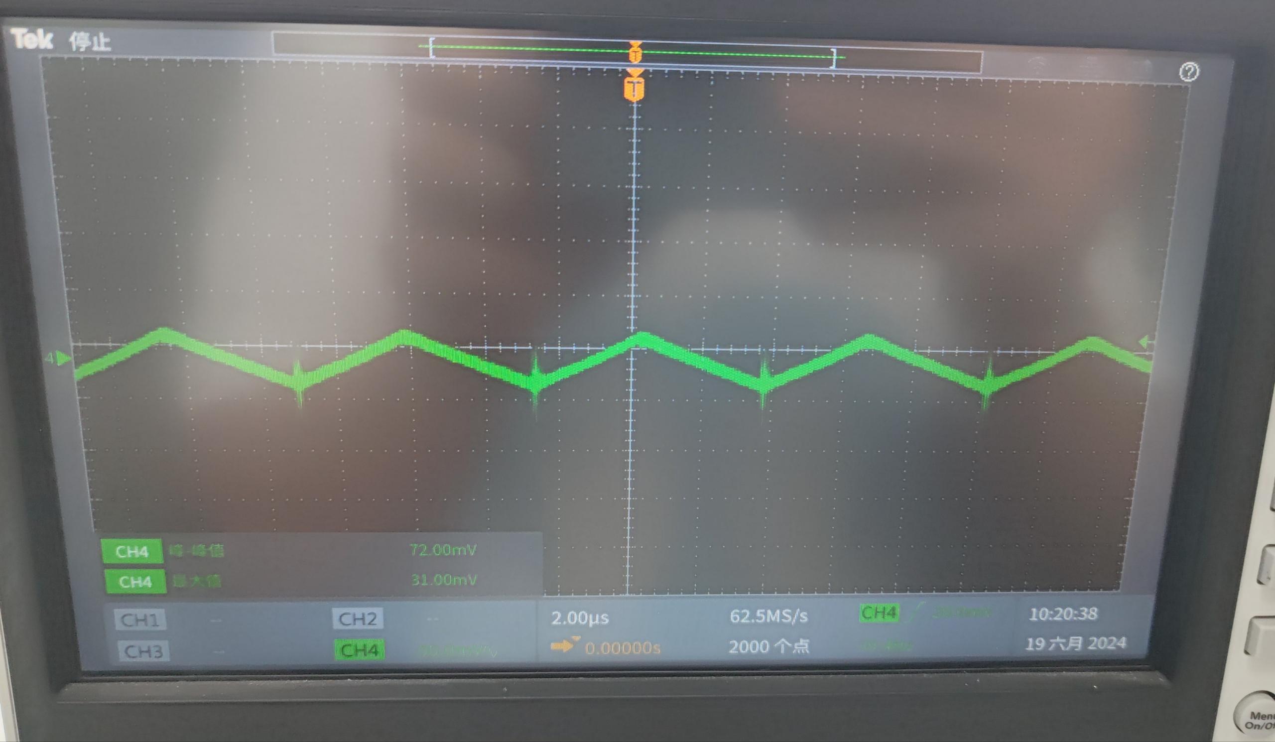
24V input, 3A load, official test output ripple. (My board layout differs slightly from the official board layout.)
Ripple at 12V input, 5V output.
2.3 Short circuit protection: Please refer to the video below.
2.4 Datasheet, calculation tables are in the attachment below.
The board is installed at the bedroom window to control two motors to open the curtains and windows. One infrared circuit is used to turn on the air conditioner and other infrared devices (or to remotely turn on the computer; the unsoldered component in the picture is an optocoupler, which can be used to turn on the computer).
The board, installed at the bedroom window, controls two motors and has one infrared path for turning on the air conditioner and other infrared devices (or for remotely powering on a computer; the unsoldered component in the diagram is an optocoupler, which can be used to power on the computer).
Application scenarios: 1. Opening curtains via a mobile app (smart speaker); 2. Opening windows via a mobile app (smart speaker); 3. Turning on/off the air conditioner via a mobile app (smart speaker).
2. Controlling a magnetic water switch for automatic watering of plants; 2. Controlling a magnetic water switch for automatic water filling of a dishwasher (modification of a manually filled dishwasher).
3. One optocoupler for remotely turning on/off a computer.
The board has been verified and works normally. Some interface designs are not ideal and will be improved later. The following code implements opening and closing the curtains and specifying their position; other functions are under development. The curtain software development has also been tested. It can be directly installed and used with any roller blind using the following curtain structure after printing the outer casing.
Currently, this code implements opening and closing the curtains and specifying their position. It has been used for half a month and functions normally. The server uses Baffa Cloud (https://cloud.bemfa.com/).
The attachments include Arduino source code and 3D model files.
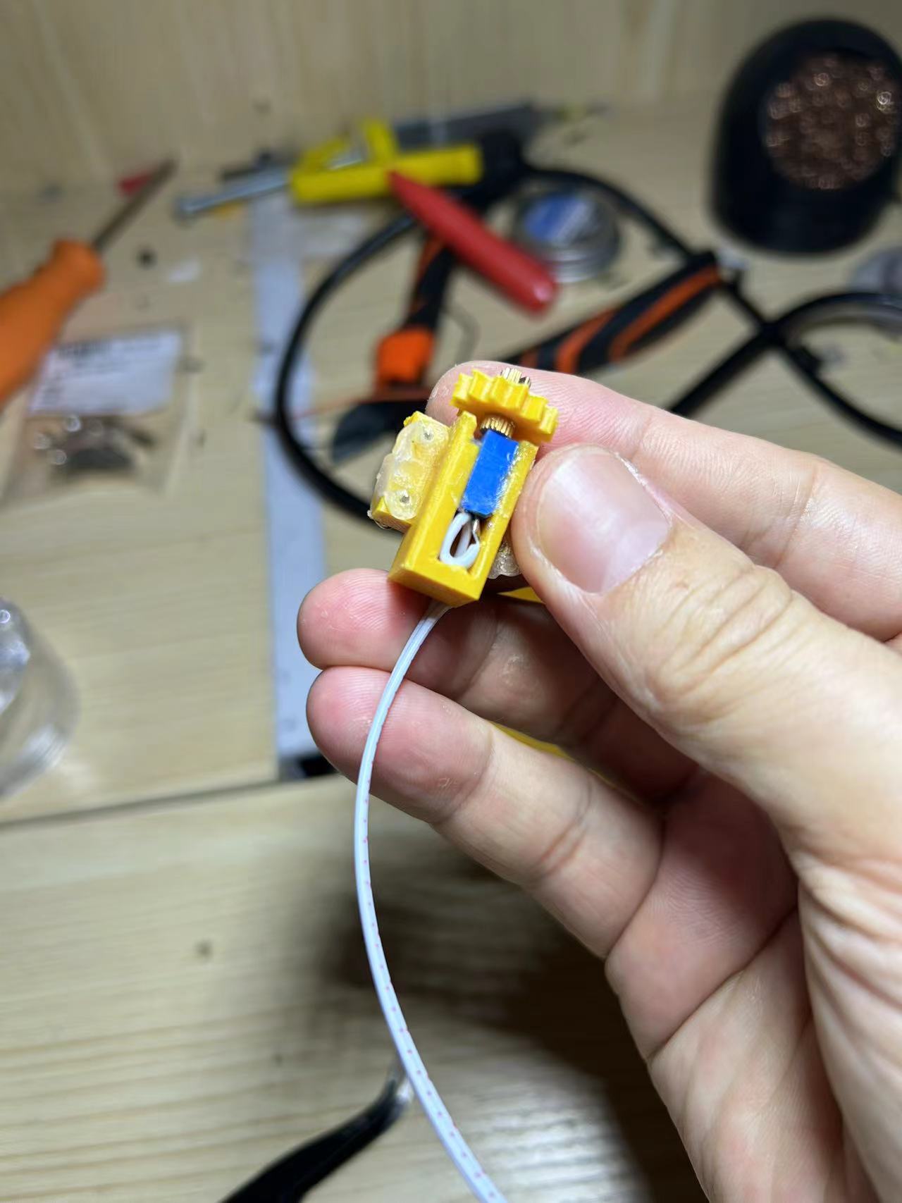
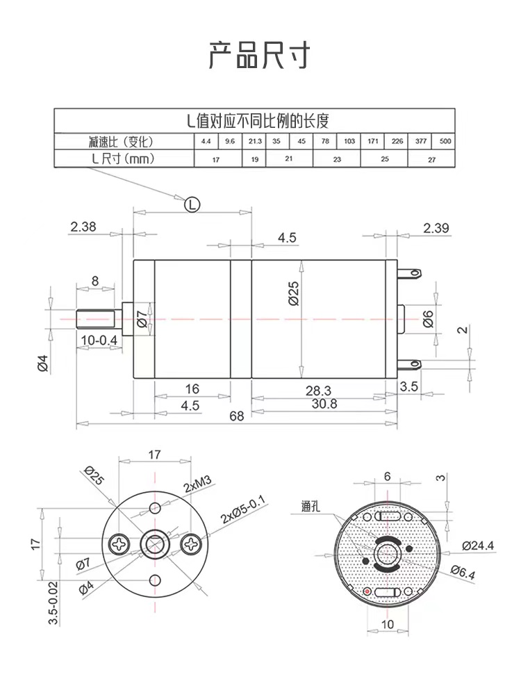
The power supply uses a 6V-12V input, depending on the motor's operating voltage. I used a 12 RPM motor; see the image below for details on purchasing one online. If you have a spare router power supply, you can use that. Because the AMS1117 manual states a maximum input of 18V, a 12V input can cause significant overheating if the microcontroller is in network configuration mode.
A copper wire can be soldered to the head to improve heat dissipation. This solution has been used for over half a month, with three curtains installed, and has not experienced any crashes, so it should be considered stable.
The motor dimensions are shown in the image below.

V1.01.ino
Part 1.STL
Part 3.STL
Part 6.STL
Part 2.STL
Case base.STL
Outer shell cover.STL
PDF_Curtain Controller.zip
Altium_CurtainController.zip
PADS_CurtainController.zip
BOM_Curtain Controller.xlsx
94185
NAS Companion - Low Power
NAS needs to run continuously, and there is a risk of power outages and restrictions in the summer. It is necessary to make a UPS uninterruptible power supply and provide a USB serial port for communication with the host.

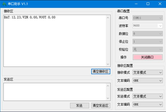
Main functions: In the event of a power outage, the battery continues to provide power and notifies the NAS system to shut down via USB-serial port.
Initially designed to fit a power bank casing, due to size and heat dissipation considerations, three 18650 power batteries were used, with an output current of less than 3A, roughly sufficient for a small host.
Three batteries were chosen because a BM3452 12V electric screwdriver was readily available for disassembly, and the three batteries, when fully charged, have a voltage of 12.6V, allowing for direct output. However, using three batteries increases circuit complexity: When the main power supply is 19V, the Buck converter step-down is used; when the main power supply is 12V, the Buck circuit does not work, the inductor and MOSFET consume energy, and there is a voltage drop of about 0.5V, preventing the battery from fully charging (this is not necessarily a bad thing, considering the limited chance of power outages, reducing battery voltage extends battery life).
2. The output battery voltage range is from 9V to 12.6V. To achieve a stable 12V output, Buck-Boost is more suitable. The JW3651 is selected, with an output of 3A.
3. The UPS needs to communicate with the host computer. The inexpensive PY32F002A is chosen, paired with the mature CH340C, avoiding the compatibility and stability issues of Wi-Fi and Bluetooth.
4. Real-time monitoring of the battery pack and individual battery voltages allows for the selection of appropriate power paths based on input, output, and battery pack conditions.
1) When the main power supply is available, the voltage is stepped down to 12.6V via a Buck converter for direct output. If the battery pack voltage is lower than the predetermined voltage, charging is initiated simultaneously.
2) When the main power supply is lost, the battery pack outputs 12V via a buck-boost converter
. 3) When the battery pack voltage is between 11-12.6V, direct output bypasses the inductor and two MOSFETs, resulting in higher efficiency.
Actual board testing revealed several issues. After adjustments using jumper wires (the PCB layout has been modified but not verified), the design functionality was achieved.

Problems, takeaways, and regrets:
1. Choosing three batteries is not cost-effective. With two batteries, buck charging and boost power supply are possible; with four batteries, boost charging and buck power supply are possible, simplifying the circuit and control logic. In actual testing, the battery voltage rarely exceeds 12V, with boost being the primary voltage. A Boost chip could be used instead. The Buck chip needs to provide both external power supply and battery charging current simultaneously. The measured SCT2450 inductor heats up to approximately 60 degrees Celsius.
2. Due to the presence of the protection board, there is sometimes a significant voltage difference between the battery negative terminal and ground, which makes it difficult to measure the battery voltage. The final solution is to unify the voltage division to the battery negative terminal and measure the negative terminal voltage separately. During charging and discharging, the current is reversed, which may result in negative voltage. After raising the voltage, the input is

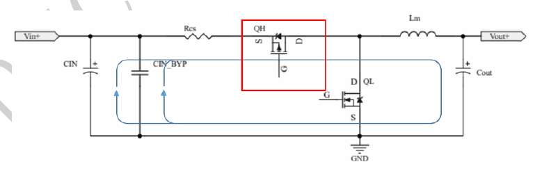
3. The charging current limit design is 0.56A, but it actually reaches 1A. The analysis shows that the PMOS is not turning off quickly enough. When R38 is 1K, the waveform is as shown in the figure. The rising edge is relatively slow, which delays the turn-off. It can be improved by replacing it with a larger package

and a smaller resistance value resistor. 4. The communication function is not yet fully completed. At present, it realizes the periodic sending of input and output and battery voltage information through the serial port, and receiving commands from the host and returning corresponding status information. The host program is relatively simple and can be written according to different NAS platforms.
5. Future upgrade ideas: replace with a larger box, a 4-cell scheme, boost charging with low current, buck power supply, replace the protection chip with one with equalization function (BM3451, pin 28), use OLED to display the status, and use IN3221 to detect input and output voltage and current.
6. Regret: There has never been a power outage.
Project.hex
PDF_NAS Companion - Low Power.zip
Altium_NAS Companion - Low Power.zip
PADS_NAS Companion - Low Power.zip
94186
Smart Mini Refrigerator
Using an STM32 as the main controller, along with an IoT Wi-Fi module, a DS18B20 temperature sensor, and the duty cycle of the STM32's output PWM, the operating status of the MOSFET and the cooling chip can be controlled remotely to achieve temperature control of the mini-fridge.
Summer is here again, and if you want to enjoy an ice-cold cola anytime while you're out, a portable mini-fridge can make all the difference.
System Design
: Main Controller: STM32 Microcontroller. The
STM32 microcontroller serves as the main controller, responsible for the logic control and data processing of the entire system.
IoT Module: Wi-Fi.
The ESP8266 Wi-Fi module enables remote communication, allowing users to control the mini-fridge remotely via their mobile phones.
Temperature Sensor: DS18B20
. The DS18B20 is a digital temperature sensor that communicates via a dedicated bus and can accurately measure ambient temperature.
PWM Control of the Cooler
: The STM32's PWM output controls the MOSFET, thereby controlling the operating state of the cooler (such as a Peltier chip). By adjusting the PWM duty cycle, the cooling capacity of the cooler can be precisely controlled.
Hardware
Power Supply: 18650 Lithium Battery
. The 18650 lithium battery provides portable power for the mini-fridge control system.
The remaining components
use hot melt adhesive, acrylic sheets, 2.54*2p and 3p terminals, a 1.5cm high 6*6 high button, a
4*4*10cm heatsink and a 4*4*4 cooling fin for the 5V cooling chip, two 4*4cm 5V small fans for cooling the step-down chip, and a 1.5*2.5*3cm heatsink for cooling the chip.
The actual steps are shown in
the internal picture; proper heat dissipation is crucial.

2. This is the power-on screen.
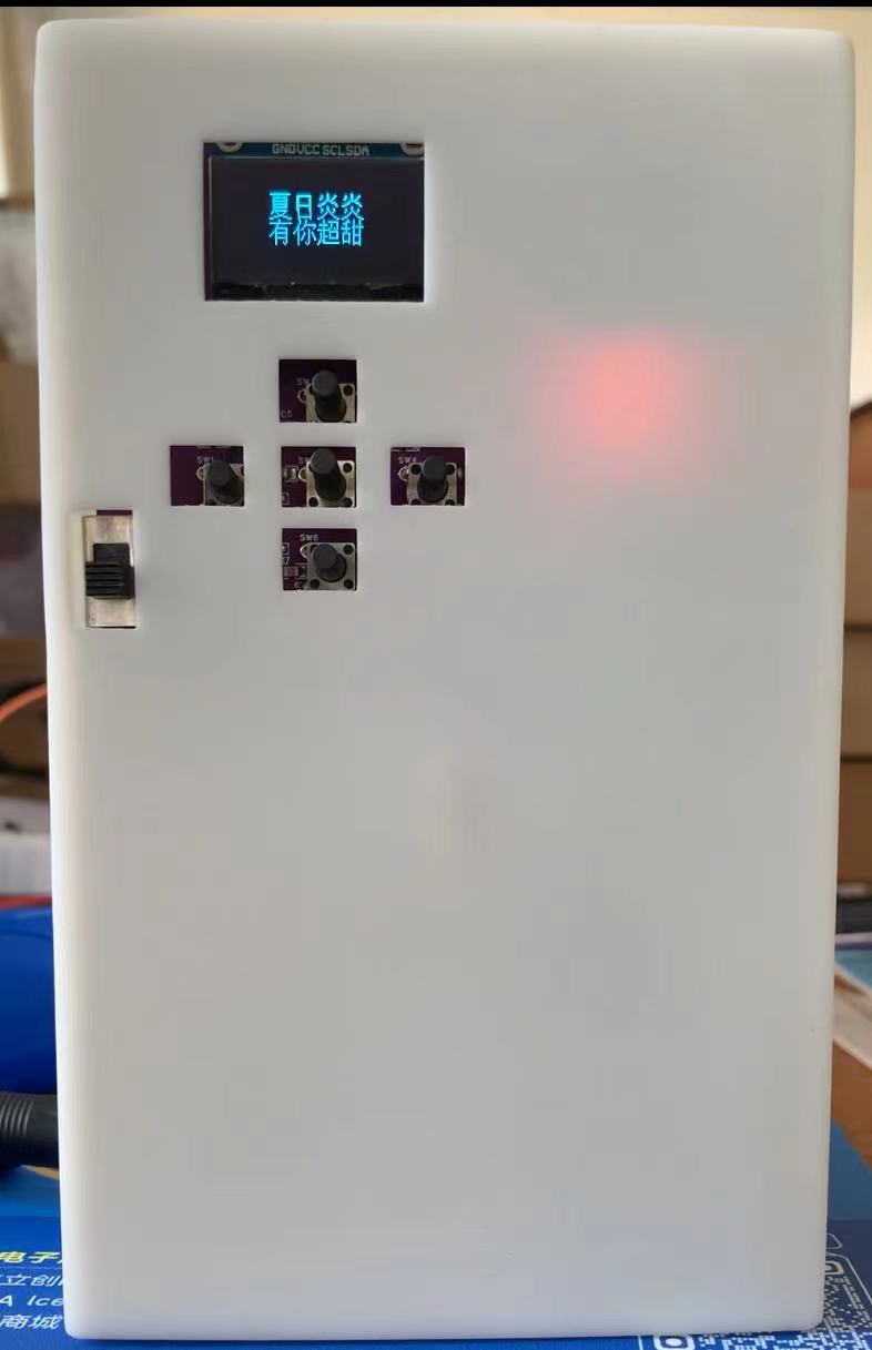
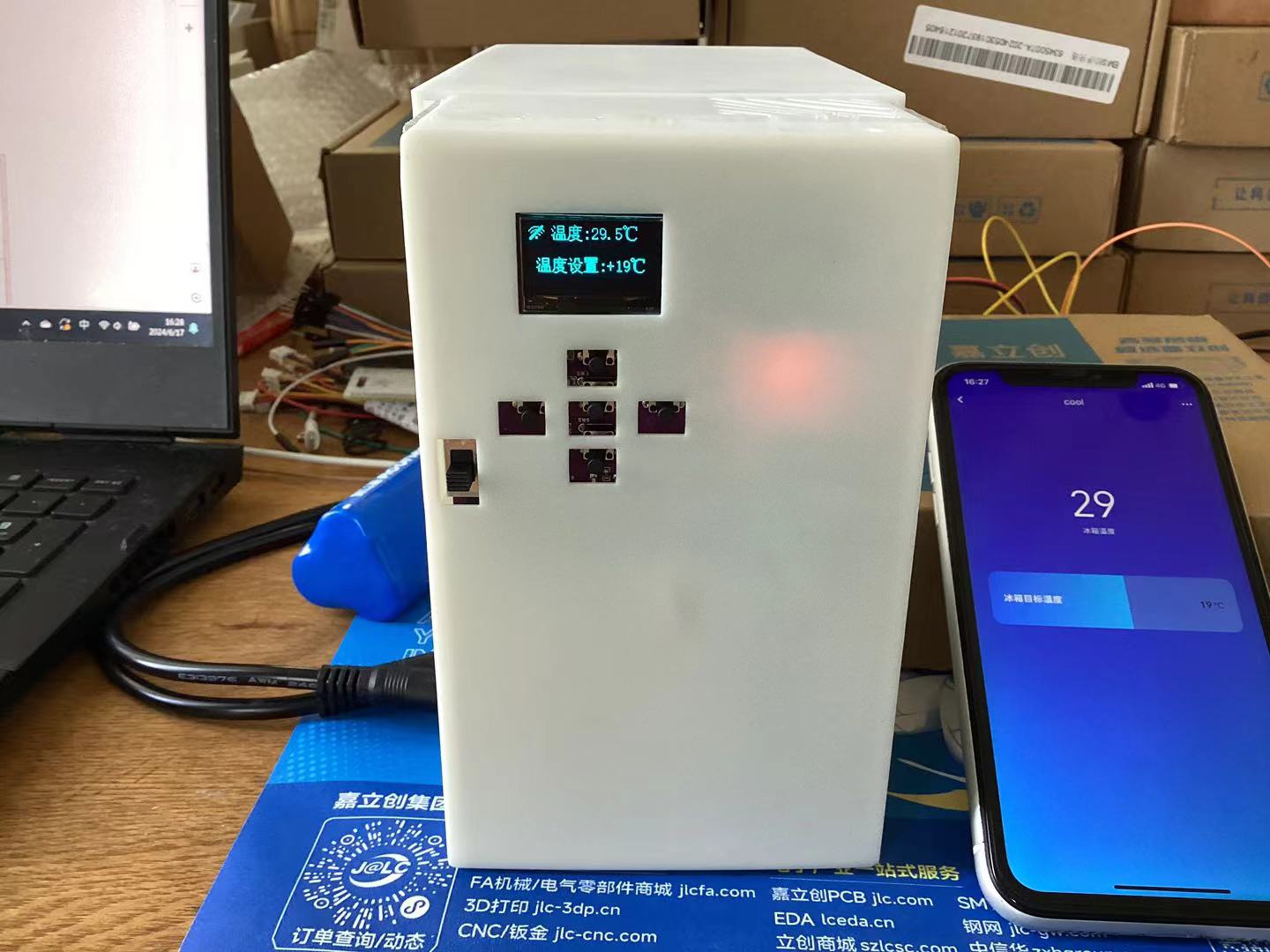
3. When powered on, a Wi-Fi icon appears in the upper right corner, indicating a network connection. The target temperature can be set via buttons or a mobile phone. The phone also displays the current refrigerator temperature. When the refrigerator temperature is higher than the target temperature, the STM32 controls the PWM output to control the PMOS transistor, enabling the cooling chip to work. When the temperature is lower than the target temperature, the cooling chip stops working.
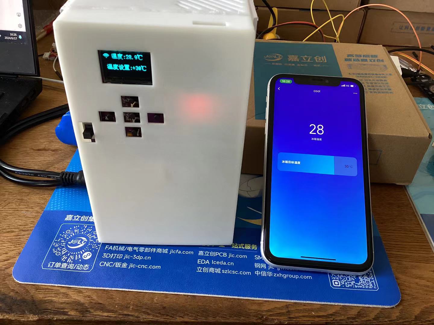
4. When the Wi-Fi icon in the upper right corner shows a "/", it means no device is connected to the Alibaba Cloud platform, and the target temperature cannot be controlled via the mobile app. In this case, the target temperature can only be set via a button. Similarly, the STM32 controls the PMOS transistor to operate the cooling chip by controlling the PWM output.
cool.mp4
code.rar
3DShell_PCB1.zip
PDF_Smart Mini Fridge.zip
Altium Smart Mini Fridge.zip
PADS Smart Mini Refrigerator.zip
BOM_Smart Mini Refrigerator.xlsx
94187
0.8-inch TM3130 Desktop Electronic Clock and Thermometer
0.4-inch desktop electronic clock and thermometer
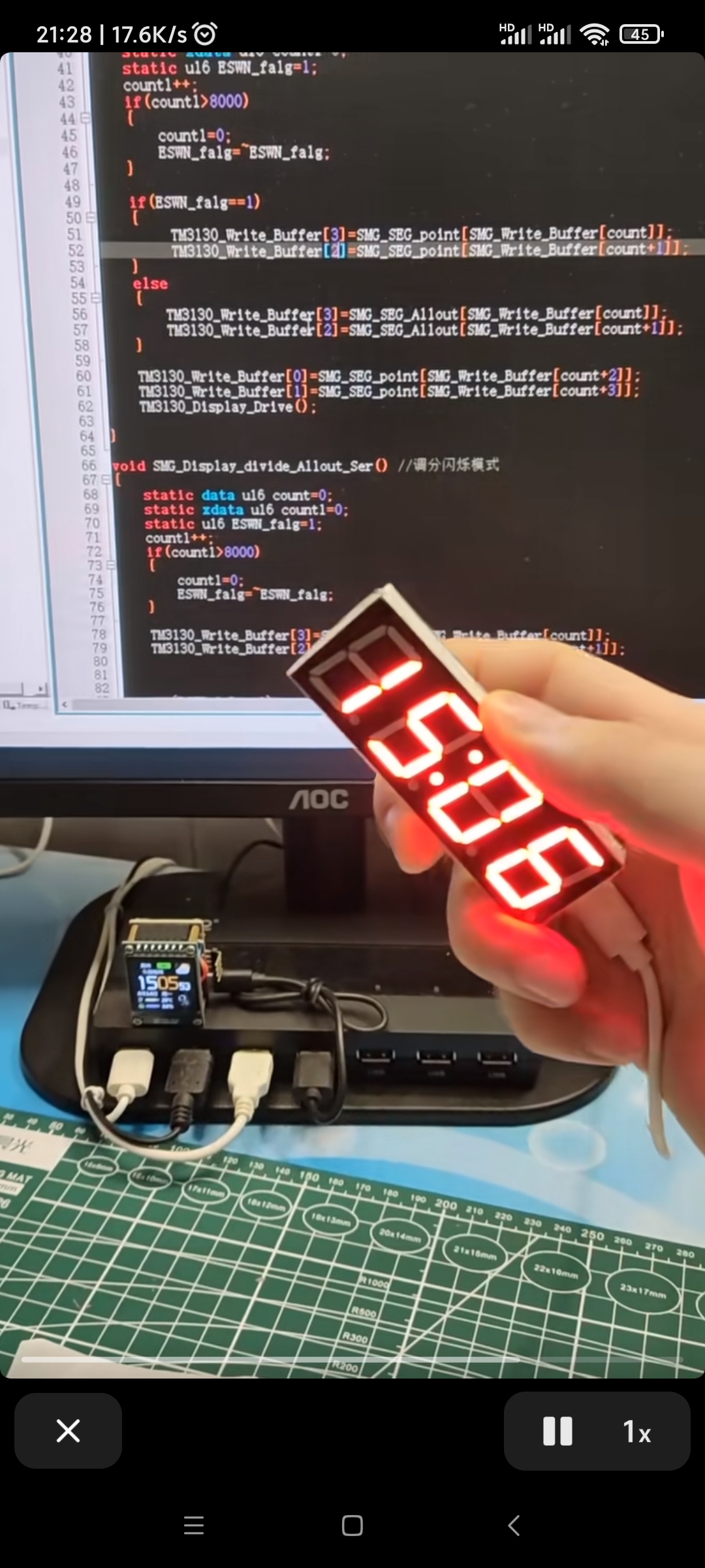
//The source code and PCB layout for the above projects are publicly available. Search "Qiqi Loves Microcontrollers" on the "LCSC Open Source Hardware Platform".// Microcontroller model: STC8G1K08 1. When programming, be sure to select built-in IRC=30MHz. 2. Set the reset pin to the IO port. 3. Uncheck the option to erase the user EEPROM area when downloading the user program.
/*No technical support provided, just sharing for fun. This is an open-source blogger's work; it is for use only
and not for commercial purposes. Questions can be discussed in the comments section below. Designer of this solution: Qiqi Douyin: The Cutest Qiqi in the Universe Kuaishou ID: Qiqi Loves Microcontrollers Bilibili: Qiqi Loves Microcontrollers QQ: 1715755109 (For custom microcontroller programs and PCB designs, add as a friend and note your purpose; paid design, serious inquiries only). QQ Group: 499067314 (Welcome all microcontroller enthusiasts to join the group; group files are available for free download.)
*/
With clock blinking.zip
1715606982031.jpg
PDF_0.8-inch TM3130 Desktop Electronic Clock and Thermometer.zip
Altium 0.8-inch TM3130 Desktop Electronic Clock and Thermometer.zip
PADS 0.8-inch TM3130 Desktop Electronic Clock and Thermometer.zip
BOM_0.8-inch TM3130 Desktop Electronic Clock and Thermometer.xlsx
94188
Pyroelectric infrared motion sensor lamp (Public)
Infrared human body sensor light
Summary: This project utilizes a D204S infrared sensor head, controlled by a BISS0001 main controller, to turn six 5730 LEDs on and off, achieving a human body detection lighting function.
Reference project: https://oshwhub.com/wzw666/chong-dian-gan-ying-xiao-ye-deng
Project overview
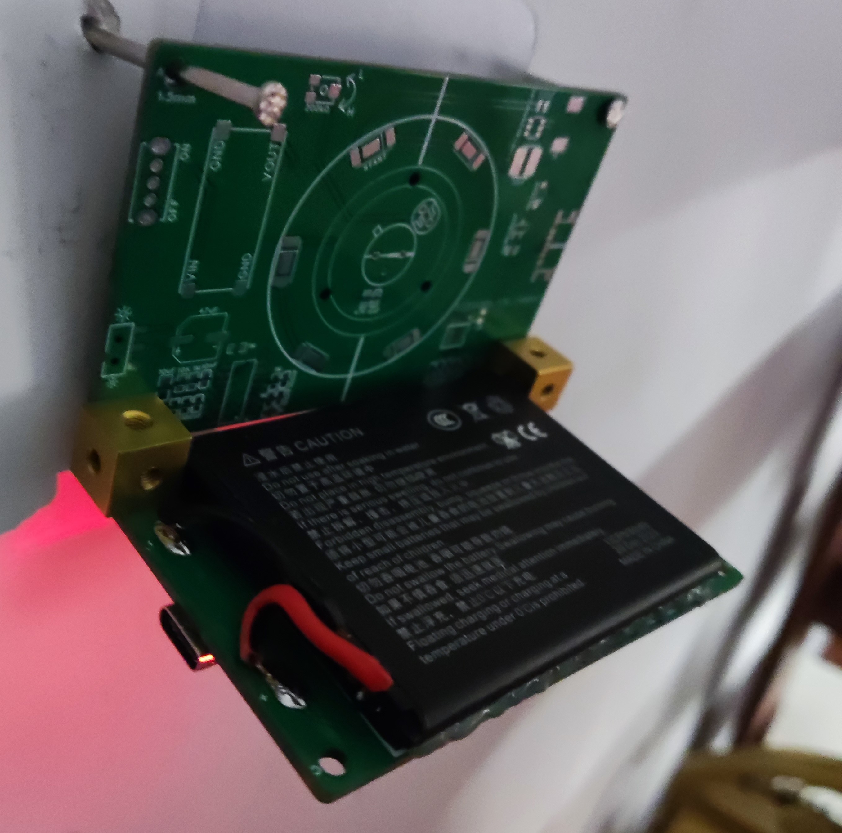
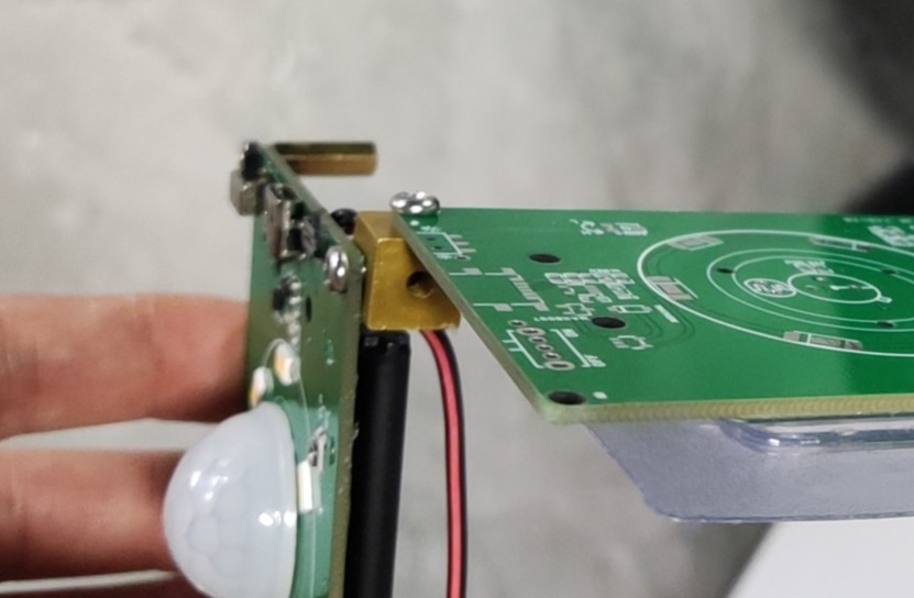
and appearance illustration. A combination of square nuts allows for 90-degree wall mounting. The red light indicates low battery . The square nut usage
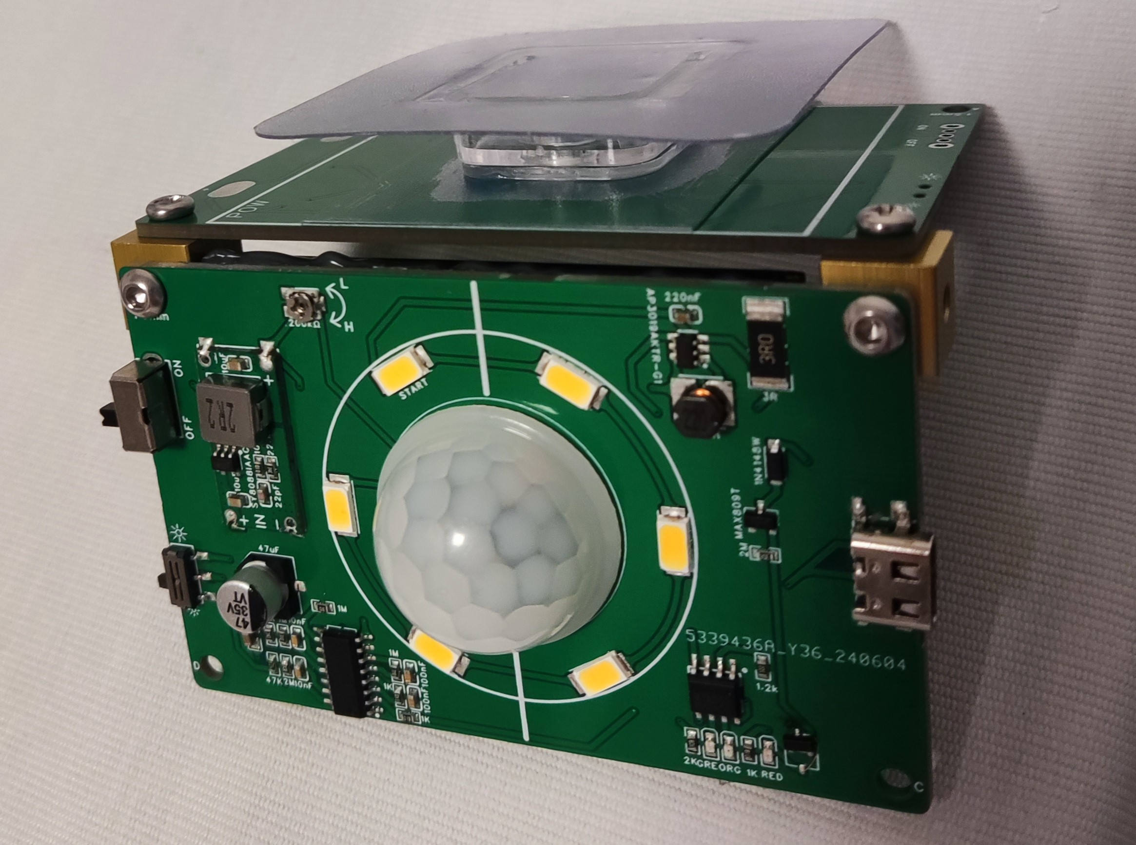
illustration shows that a copper pillar can be used to elevate the back when 90-degree wall mounting is not required. Battery Precautions (Important): Use polymer batteries, with dimensions less than 63 * 50 mm. I cannot provide a purchase link; these were found elsewhere. Polymer batteries within this size range can be used. (Important) The power supply uses a SY8088AAC switching power supply chip, which is stacked on this board and cannot be purchased elsewhere!! (You can draw your own or use a voltage regulator chip). Do not directly connect a lithium battery to the main controller or infrared sensor. The unstable voltage of the lithium battery will definitely cause the infrared sensor to falsely trigger . The D204S is extremely easy to damage. Minimize soldering time. During soldering, it should be suspended 4mm away from the PCB; otherwise, it is easy to falsely trigger the low battery warning and the power will not disconnect when the main switch is turned off, causing a short circuit. The cost is around 10 RMB, plus the battery (I considered the battery as a find). The sensor and chip are relatively expensive . The LED color temperature can be adjusted. My mother likes white, but I prefer 4000k warm light. The hole size on the board is 1.5mm, and the radius is M3. Note this when purchasing (not important). The 4054 series can also be used for charging. I used it on a previous board; it charged at 3000mA overnight and the sky was already bright... (Not important) The large switch is the main power switch, and the small switch is for selecting the single-time light-on strategy; the headlight icon will remain constantly lit if triggered within n seconds (15 seconds in this solution); the small light icon will definitely turn off after n seconds, and the infrared probe signal will be read again after 1~2 seconds of signal stop. Materials not mentioned in the guide are available on Taobao and WeChat. Brand new PIR pyroelectric human infrared sensors D203S D203B D204S D204B D205B original ¥1.71; LED driver AP3019AKTR-G1; DIODES (US/Taiwan) SOT-23-6 silkscreen GAS brand new free shipping ¥0.5; Human body sensor BISS0001 UMW (Taiwanese semiconductor) SOP-16 universal infrared pyroelectric ¥0.5; M3M4/5/6/8 aluminum alloy six-sided three-way nut screw hole colored connecting block chassis shock-absorbing feet; DIY salvaged battery (reference link). 6. Strong waterproof bathroom adhesive multi-functional traceless snap-on clip for fixing power strips without drilling ¥4.5 TODO LIST Using nuts and nuts is just to avoid drawing the outer casing; I'll draw it when I have time... placeholder


VID_20240613_132702.mp4
PDF_Pyroelectric Infrared Human Body Induction Lamp (Public).zip
Altium_Pyroelectric Infrared Human Body Sensor Lamp (Public).zip
PADS_Pyroelectric Infrared Human Body Induction Lamp (Public).zip
BOM_Pyroelectric Infrared Human Body Induction Lamp (Public).xlsx
94189
electronic


 京公网安备 11010802033920号

 1N6294E3TR


