
 1. An SS36 Schottky diode is used at the input for reverse connection protection. Its function is to protect the chip from damage if the input power is reversed. The advantage of using a diode is its low price, but the disadvantage is slightly higher power loss.
  2. Four 10uF, 35V X5R MLCC capacitors are used for the input. According to the official reference calculation document, the minimum input capacitance is 47uF. Therefore, four 10uF, 35V MLCC capacitors and one 0.1uF, 50V X7R MLCC capacitor are connected in parallel. These five capacitors should be placed close to the VIN pin during PCB layout.
  3. Inductor selection: Using the official table, input voltage, output voltage, and current were entered. After calculation, a reference inductance of 20.6uH was chosen. However, this value is unavailable, so a 22uH inductor was selected. Shielded inductors are preferable to reduce EMI and improve stability and safety. Since a 22uH inductor was unavailable, a 47uH/3A inductor was used.
 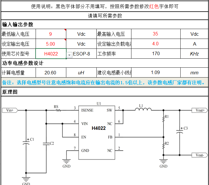 4. Output capacitor selection: Four 22uF, 25V X5R capacitors were chosen. The table references 1000uf/16V electrolytic capacitors. Due to the higher equivalent ESR of electrolytic capacitors, four 22uF capacitors and one 0.1uf MLCC capacitor were ultimately selected.
  5. The feedback voltage sampling resistor uses 31.6K, and 10k±1% forms the feedback network. These two values are readily available; alternatively, values from the reference table can be used.
 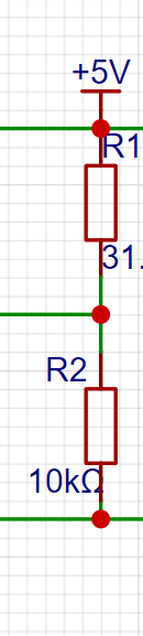 6. A red LED is included as a power indicator, and a 4.7K current-limiting resistor is used.
 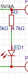 II. Layout Requirements
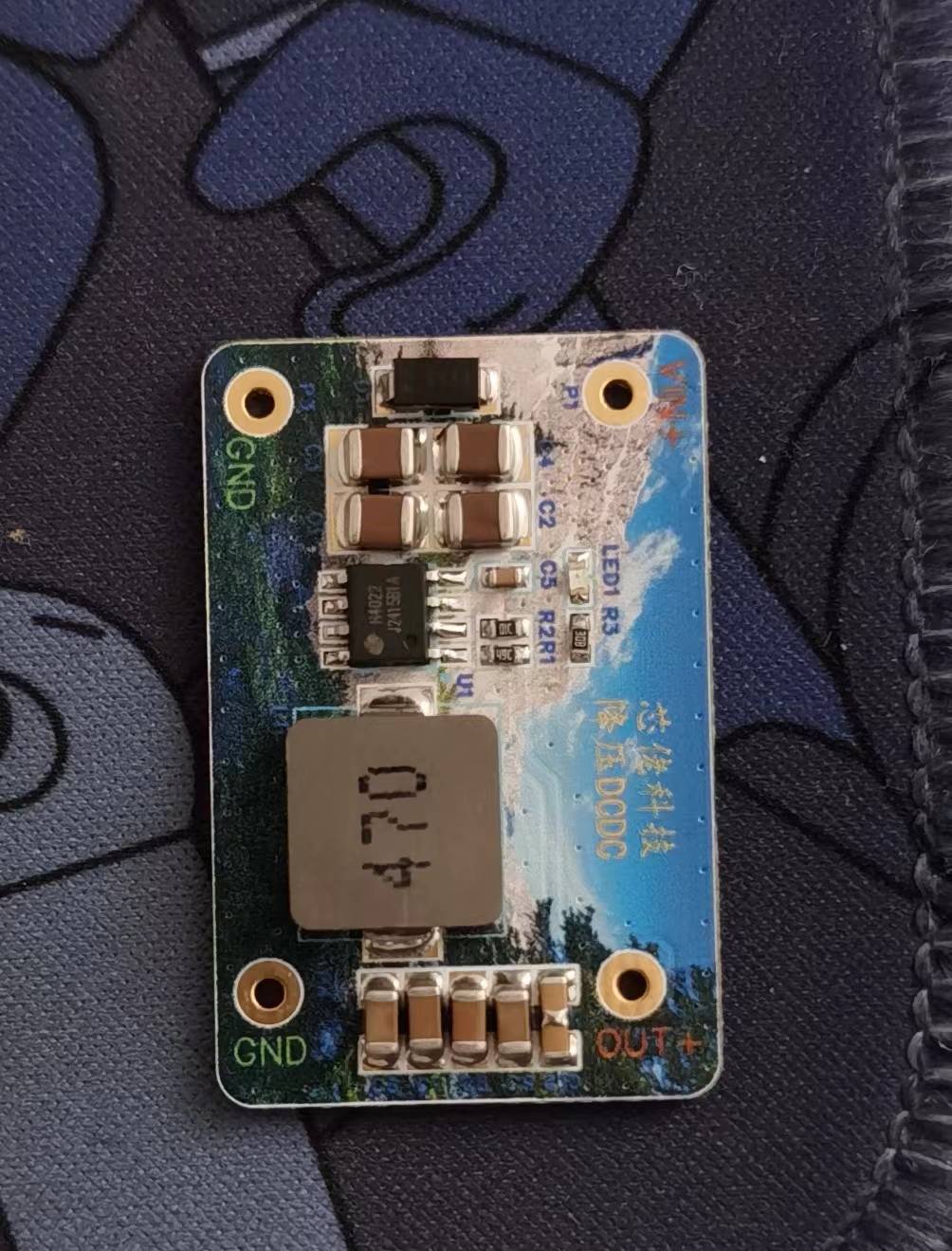
  Based on the reference guidelines, the following is my personal layout; please forgive any shortcomings. This prototype uses immersion gold color silkscreen printing.
  2.1 Due to the inherent ±1% error of the resistors, the measured output voltage accuracy is ±1%.
  2.2 No-load ripple: Due to the limited equipment and lack of a load cell, the measured no-load ripple is 10-20mV. For chips under 1 unit, this is considered a high-performance chip.
 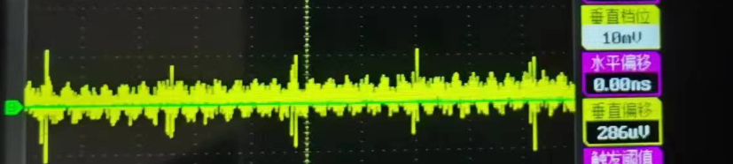 24V input, 3A load, official test output ripple. (My board layout differs slightly from the official board layout.)
 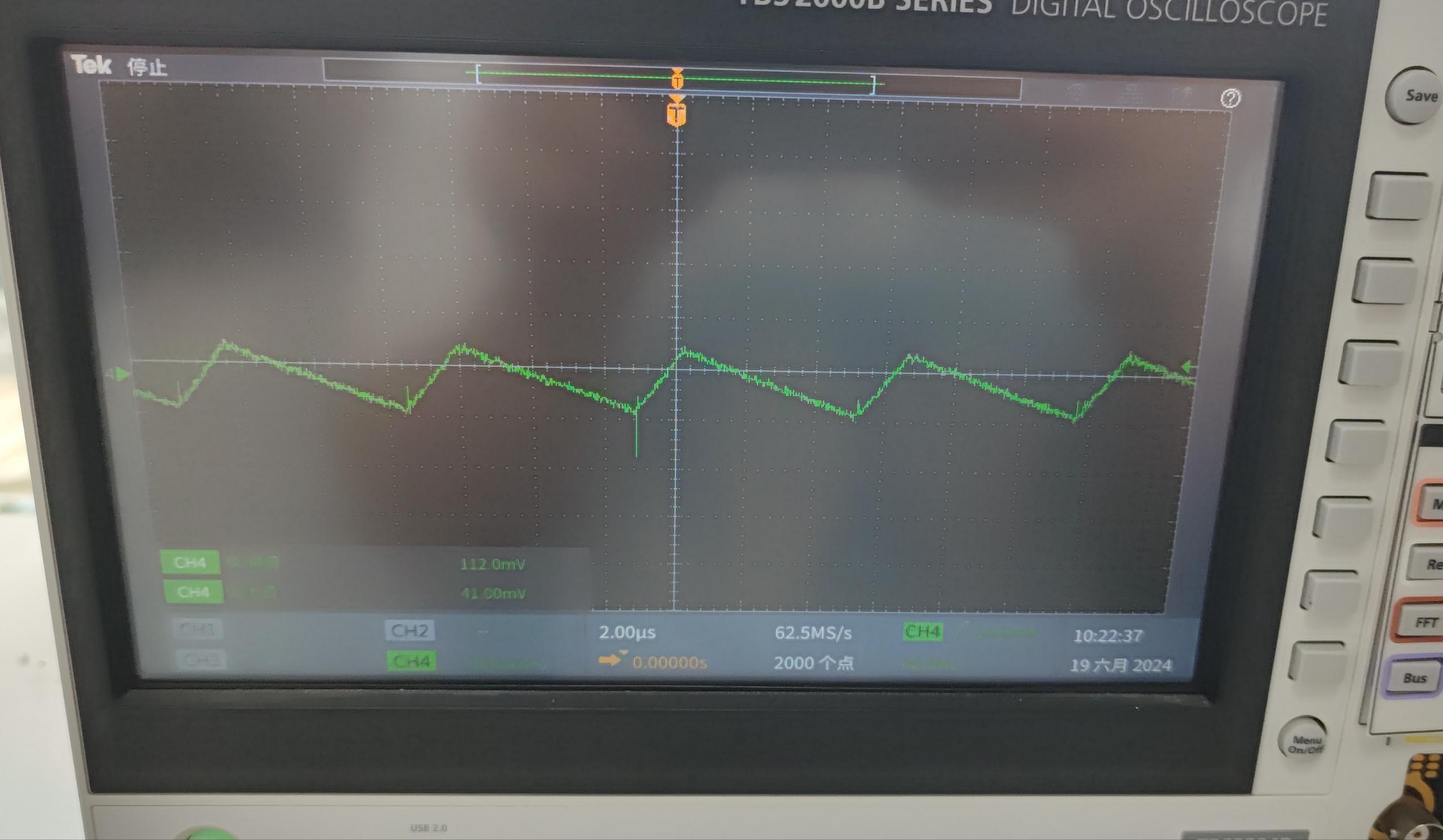 Ripple at 12V input, 5V output.
 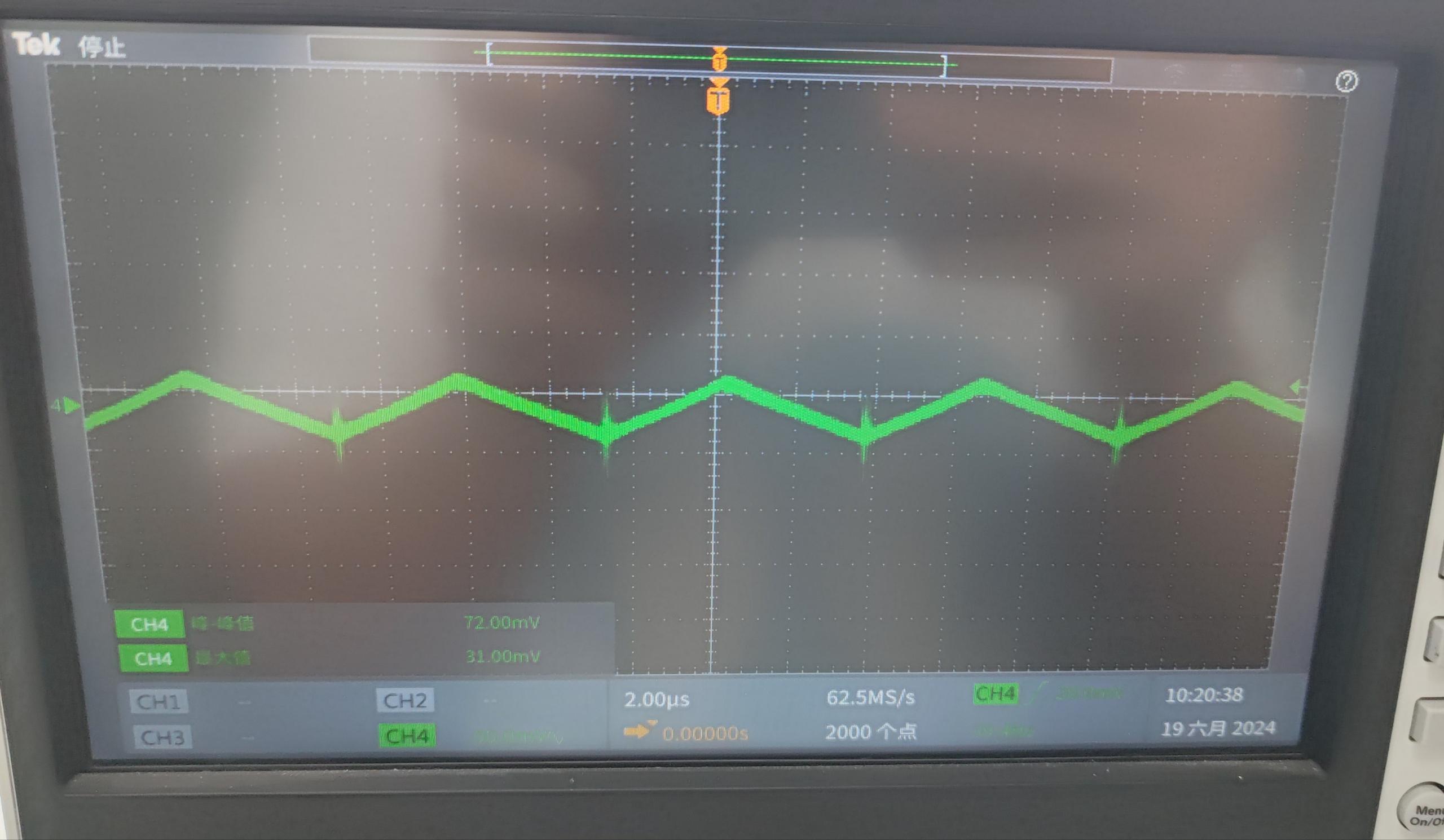 2.3 Short circuit protection: Please refer to the video below.
All reference designs on this site are sourced from major semiconductor manufacturers or collected online for learning and research. The copyright belongs to the semiconductor manufacturer or the original author. If you believe that the reference design of this site infringes upon your relevant rights and interests, please send us a rights notice. As a neutral platform service provider, we will take measures to delete the relevant content in accordance with relevant laws after receiving the relevant notice from the rights holder. Please send relevant notifications to email: bbs_service@eeworld.com.cn.
It is your responsibility to test the circuit yourself and determine its suitability for you. EEWorld will not be liable for direct, indirect, special, incidental, consequential or punitive damages arising from any cause or anything connected to any reference design used.
Supported by EEWorld Datasheet
EEWorld
subscription
account

EEWorld
service
account

Automotive
development
community

Robot
development
community

About Us Customer Service Contact Information Datasheet Sitemap LatestNews


Room 1530, 15th Floor, Building B,
No.18 Zhongguancun Street,
Haidian District,
Beijing, Postal Code: 100190
China
Telephone: 008610 8235 0740
 京公网安备 11010802033920号

 APL431CKI-PB


