Fursuit fans were popping up like mushrooms after a rain, so I followed suit and made a speed control head for the fan. However, this seems to be something made last year.
! ! Without written authorization, no one is allowed to sell this module or provide this module as any additional service! !
(Whether firmware is burned or not, this article is subject to the restrictions)
——————————————————————————————— ————————————
Button logic
There is only one button on the entire speed control head, which is also the BOOT button:
press to power on to enter the flash mode, which is used to flash firmware to the microcontroller.
Power on normally without pressing the button. If the firmware has been successfully flashed into the microcontroller, the speed can be adjusted normally.
In the speed adjustment mode, click the button to increase the fan speed. There are four gears (DC: 0V-5V-9V-12V/PWM: 0%-40%-70%-100% (approximate)). If it has reached the highest The gear position will automatically return to zero;
long press the button to change the speed adjustment method between DC and PWM (for adapting to 2-wire/4-wire fans).
In addition, the module has a power-off memory function. The last gear and speed adjustment method used in the speed adjustment mode will be automatically recorded in the EEPROM for reading next time it is turned on.
Speed control mode
This speed control module has two speed control modes: DC (PD) and PWM.
The PWM mode can only be used to adjust the speed of the four-wire fan: In this mode, the 1 light is always on, the 3 light is off (12V permanent), the darker the D light, the higher the fan gear.
DC mode can be used to adjust the speed of two-wire and four-wire fans; in this mode, the D light does not light up (PWM 100% resident). The relationship between the on and off of lights 1 and 3 and the voltage can be referred to the truth table in the figure below.
1 light on
1 light off
3 light on
9V
5V
3 light off
12V
open circuit
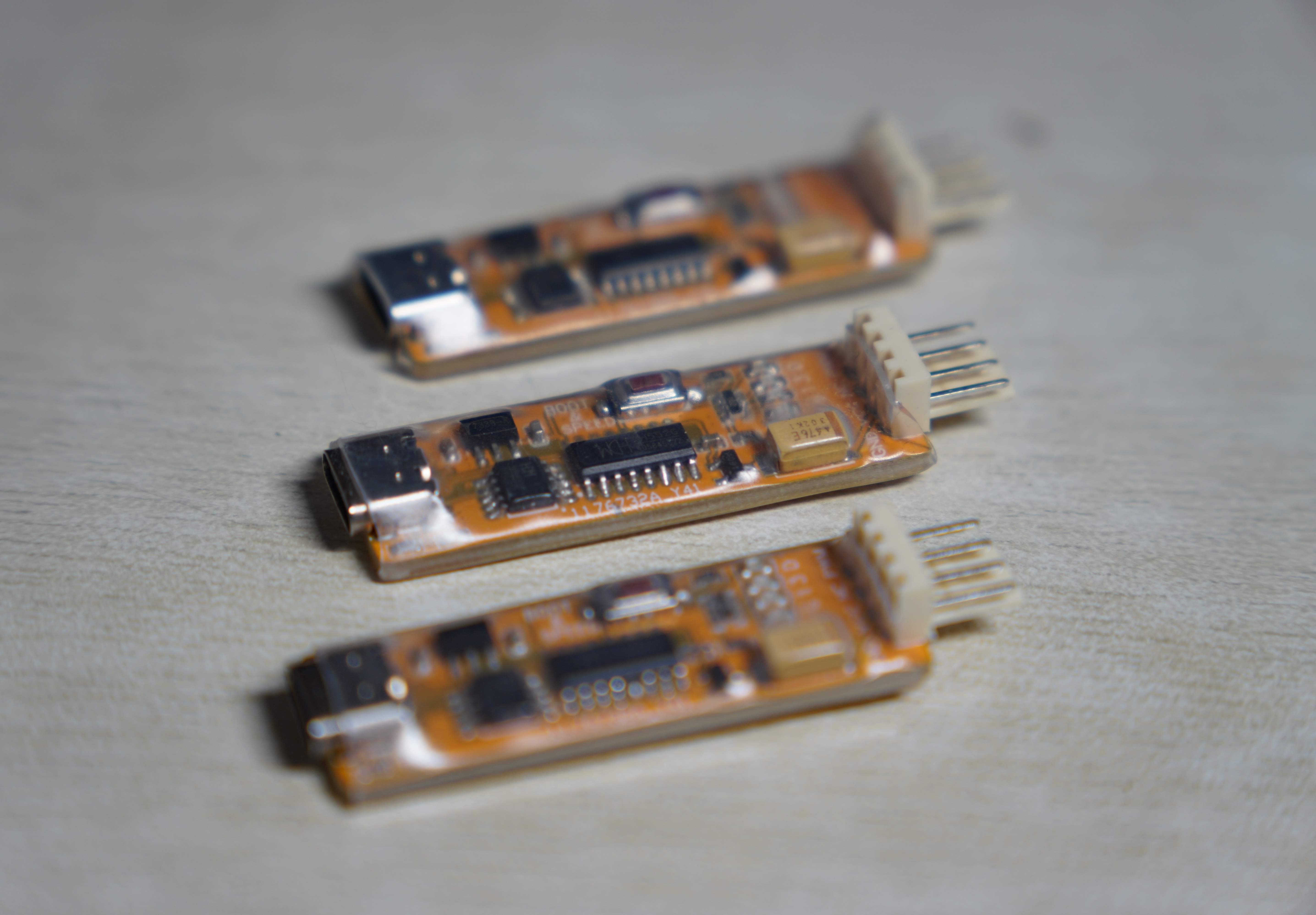
Since the rated voltage of the fan I used is 12V, I pulled down the CFG2 of CH224K on the hardware to prevent the two voltages of 15V and 20V from being pulled out.
In addition, after testing, this board (early version) will leak electricity (about 1W) and generate heat when it is pulled to 20V. This may be because the school does not have a ground wire, or the LDO is of poor quality. There are five LED indicators on the
LED indicator
board: P(ower) (Power)G(ood) (CFG)1 (CFG)3 D(uty). It is recommended to weld according to the ABCCD light color combination to facilitate visual identification.
The PCB is yellow, and the colors of the LEDs I soldered are red, green, yellow, yellow, and blue.
The P light is used to indicate full board power supply. When the LDO buck circuit outputs normally, the P light is always on.
The G light is used to indicate the PD handshake status. When CH224K is shaking hands with the power supply, or after switching gears, the G light will go out; when the CH224K handshake is successful, the G light will always be on.
Lights 1 and 3 are used to indicate the CH224K target voltage. For detailed correspondence, please refer to the previous explanation of the speed adjustment mode.
The D light is used to indicate the PWM duty cycle. The brighter it is, the lower the duty cycle is. The darker it is, the higher the duty cycle. When it is turned off, it reaches 100% duty cycle.
P.S.
When CH552G is powered on for the first time, it can enter the burning mode without pressing a button!
If the chip you bought does not automatically enter the programming mode after being soldered to the finished product, congratulations on buying a refurbished chip.
Warm reminder, the CH552G's Flash only has a lifespan of more than a hundred times of erasing and writing, so don't ravage the E8051, which costs more than a dollar a piece.
Welcome passing saints to help continue to improve the firmware!
Features currently missing: EEPROM erase and write equalization.
Current problems: (1) The LDO and interface are slightly hot (2) When connected to the PD charger, the CH552G cannot be started immediately. It is speculated that it is related to the USB handshake or the like, which affects the boot pin.


 京公网安备 11010802033920号

 1812N160F201YT


