9bggZf

52x52x80 IP2366 4-cell battery module [Verified]

 
Overview
This project utilizes a 4-cell 16V battery pack based on the IP2366 main controller and CW1244 battery protection chip. It supports MPPT (Maximum Power Point Tracking) input and is compact and lightweight, suitable for everyday use. 2. Application Scenarios: Power supply for high-power digital devices. 3. Product Overview: This product is a 4-cell 21700 battery pack module, supporting a maximum PD20V3A input, MPPT input, PD20V3A output, and DC (XT30+XT60) 16V20A300W output. Verified. The casing is made of 52*52*80mm aluminum profile. 4. Product Parameters: Main Controller: IP2366; USB-C Input/Output: 5V3A, 9V3A, 12V3A, 15V3A, 20V3A; Battery Parameter Configuration: Cut-off Voltage: 4.2V (see IP2366 datasheet for details); Battery Selection: Standard size or slightly larger 21700 lithium batteries. (Diameter not exceeding 22mm) Protection board parameters: Supports 20A discharge and 8A charging when 4-cell batteries are soldered with two 5mR sampling resistors. Supports equalization function and equalization indicator function. Interface XT30 shell specifications: 52*52*80mm standard aluminum profile shell, which can be purchased for around ten yuan on Taobao. Reference purchase link: You can find shells of the same specifications yourself; many manufacturers produce this specification. 5. Manufacturing method: Directly make a sample, then purchase the components according to the BOM list, solder according to the PCB file, and after successful assembly, assemble the shell according to the specifications, solder the batteries, and perform charging test. This is a purely hardware-based project with no programming involved. Once soldered, it's ready to use and can be charged. 6. Notes: 1. Items not listed in the BOM (Bill of Materials) may need to be procured separately. 2. Pay attention to the length of the XT30 interface cable for the battery pack to avoid assembly errors. 3. Ensure the vertical USB-C port is at least 13mm high in height. 4. Use high-rate batteries for minimal heat generation during charging and discharging, such as the Lishen 2170LA. 5. Specifications are in the appendix. 6. This project requires soldering the QFN. Please ensure you have sufficient PCB soldering experience and skills, as well as the necessary equipment (soldering iron, hot air gun, teppanyaki grill, etc.) to complete the entire project. 7. The estimated BOM cost for this project is approximately 100 RMB.
PDF_52X52X80 ip2366 4-cell battery module [Verified].zip
Altium_52X52X80 ip2366 4-cell battery module [Verified].zip
PADS_52X52X80 ip2366 4-cell battery module [Verified].zip
BOM_52X52X80 ip2366 4-cell battery module [Verified].xlsx
94243
AIR001 Electronic Scale
Electronic scale with an accuracy of ±1 gram
The product is very simple... a weighing module... It uses the AIR001 from Heze as the main controller,
and two aluminum substrates are used as mounting points for the upper and lower platforms. Two M4 screws are used for fixing it in the middle. The
only problem might be that a connecting post might need to be printed in the middle.
[https://detail.tmall.com/item.htm?id=613006248043&spm=a1z09.2.0.0.43d92e8dK8X3ee&_u=e140dm77221](https://detail.tmall.com/item.htm?id=613006248043&spm=a1z09.2.0.0.43d92e8 ) [https://item.taobao.com/item.htm?spm=a1z09.2.0.0.43d92e8](https://item.taobao.com/item.htm?spm=a1z09.2.0.0.43d92e8 ) The charging module (dK8X3ee&id=681466242060&_u=e140dm76e28&skuId=5051531982532) is available here: [link to charging module]. The battery ( https://detail.tmall.com/item.htm?id=737413082352&spm=a1z09.2.0.0.43d92e8dK8X3ee&_u=e140dm79d9c ) can be purchased with a coupon; the whole thing should cost less than 10 yuan. The code is very simple, just a quick Arduino code. (Long press to power off (actually just turns off the screen), so it still consumes power...) I added a switch to reset it to 0 for short presses to prevent it from running out of power when not in use. The code and compiled version are attached; you can modify them yourself.


test.bin
Pillar.gcode
dianzichen.ino
PDF_AIR001 Electronic Scale.zip
Altium_AIR001 electronic scale.zip
PADS_AIR001 electronic scale.zip
BOM_AIR001 Electronic Scale.xlsx
94245
motion timer
https://oshwhub.com/shaoki/ups-power-supply
1. Remind yourself to change poses periodically while doing yoga.
2. Desktop clock/alarm clock.
3. A magnetic slot is provided so it can be attached to the refrigerator and used as a timer while cooking.
4. Issues encountered during testing: The magnetic slot is too small; more space could be provided for a larger magnet; the buzzer is a bit quiet and needs to be replaced with a more powerful one.
41cdc540a9c26dfa91acfc4f6f6acb7e.mp4
PDF_MotionTimer.zip
Altium_MotionTimer.zip
PADS_MotionTimer.zip
BOM_MotionTimer.xlsx
94246
4-in-1 NFC Card - Template
A standard card-sized 4-in-1 NFC card template, easy for DIY design.
With the widespread adoption of mobile payments, identity verification, and data exchange, NFC technology has become an indispensable part of modern electronic devices due to its convenience and security. To meet market demand for multifunctional, highly integrated NFC cards, we launched the 4-in-1 Multifunctional NFC Card PCB Design and Manufacturing Project. This project aims to provide a ready-made NFC card template for free DIY design,
utilizing 0402 packaged components and COB packaged chips to achieve high-density integration and reduce PCB size.
It ensures the PCB supports various NFC applications, such as mobile payments, identity verification, data exchange, and information display.
The appropriate number of PCB layers is selected based on functional requirements and signal integrity requirements. This project provides verified two-layer and four-layer board project files, as well as partially completed main projects.
Currently, the main project, COD-ATLAS , will be continuously updated based on specific needs.
 
 
Material Connections.xlsx
PDF_4-in-1 NFC Card Template.zip
Altium 4-in-1 NFC Card Template.zip
PADS 4-in-1 NFC Card Template.zip
BOM_4-in-1 NFC Card - Template.xlsx
94248
STC8G1K08 Development Board
The STC8G1K08 development board includes PWM, CAN bus, hardware IIC, USART serial port, and power-down function. It is suitable for small product development, affordable and feature-rich. Verify product functionality before considering physical product manufacturing.
The STC8G1K08 development board integrates an iIC OLED screen interface, a dual-digit eight-segment common anode LED display, a buzzer module, an eight-digit common anode LED display, a four-button module, and uses the CH340 serial port tool module. It can be downloaded using the official STC serial port tool. It supports both software and static reset.
Backplate.SLDPRT
Cover plate.SLDPRT
June 14.mp4
PDF_STC8G1K08 development board.zip
Altium_STC8G1K08 development board.zip
PADS_STC8G1K08 development board.zip
BOM_STC8G1K08 development board.xlsx
94250
CH340K USB to TTL Serial Communication Module (with Isolation)
A friend of mine needed to use a serial port module with isolated electrical characteristics, so this project came about.
Function 1: Isolation function (normal)
Function 2: Signal transmission function (verified to be error-free at 115200 baud rate)
Function 3: ESD protection (normal)
Function 4: Support for 5V and 3.3V systems (normal, switchable via button)


PDF_CH340K USB to TTL Serial Communication Module (with Isolation).zip
Altium_CH340K USB to TTL Serial Communication Module (with Isolation).zip
PADS_CH340K USB to TTL Serial Communication Module (with Isolation).zip
BOM_CH340K USB to TTL Serial Communication Module (with Isolation).xlsx
94251
MSO5000/DHO900 Logic Probe
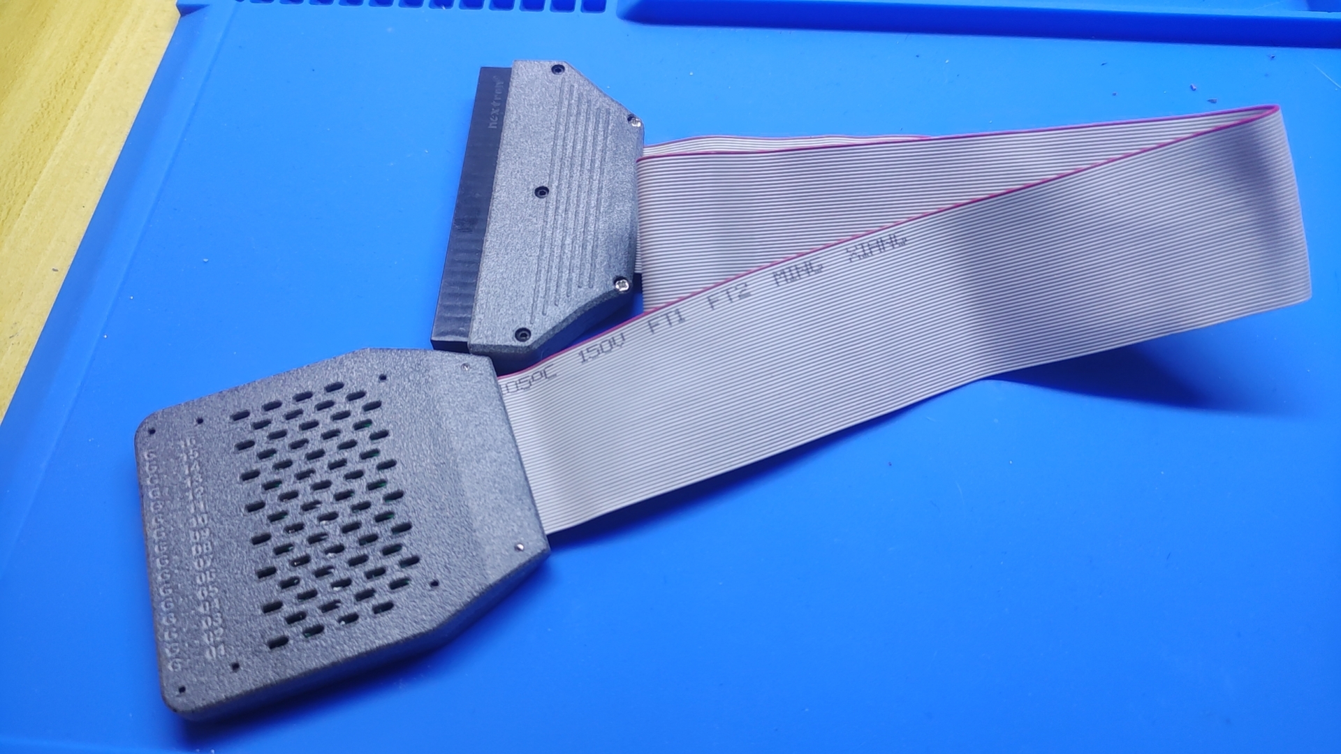
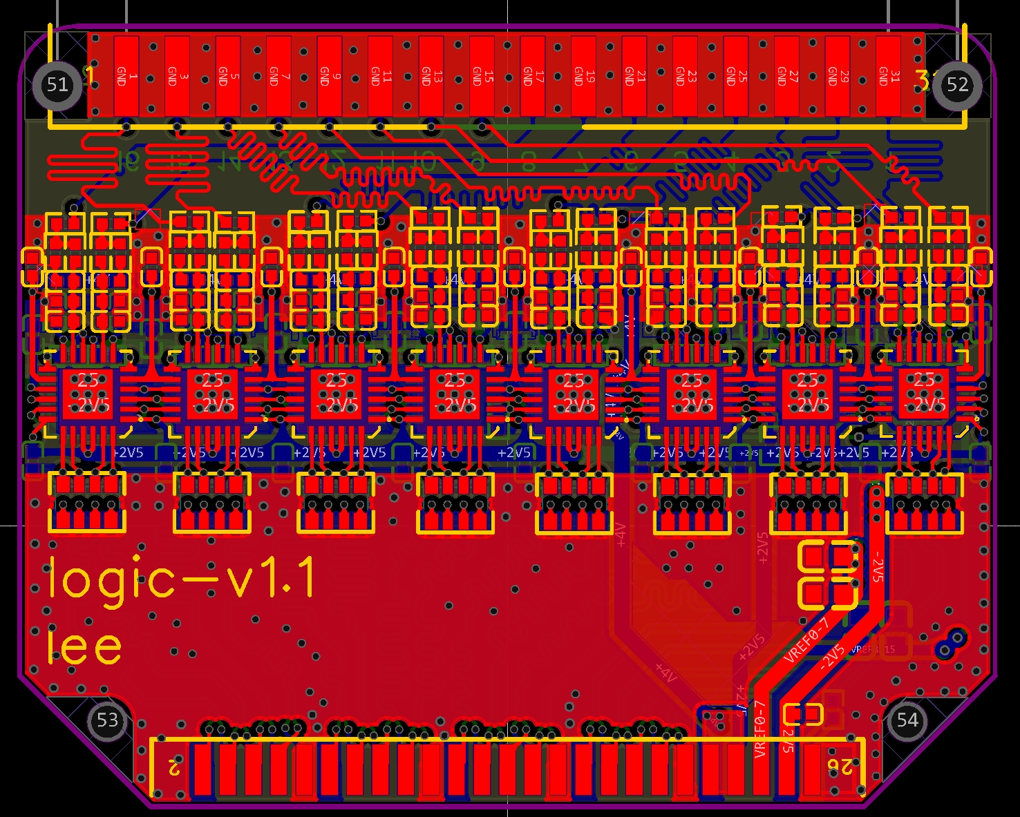
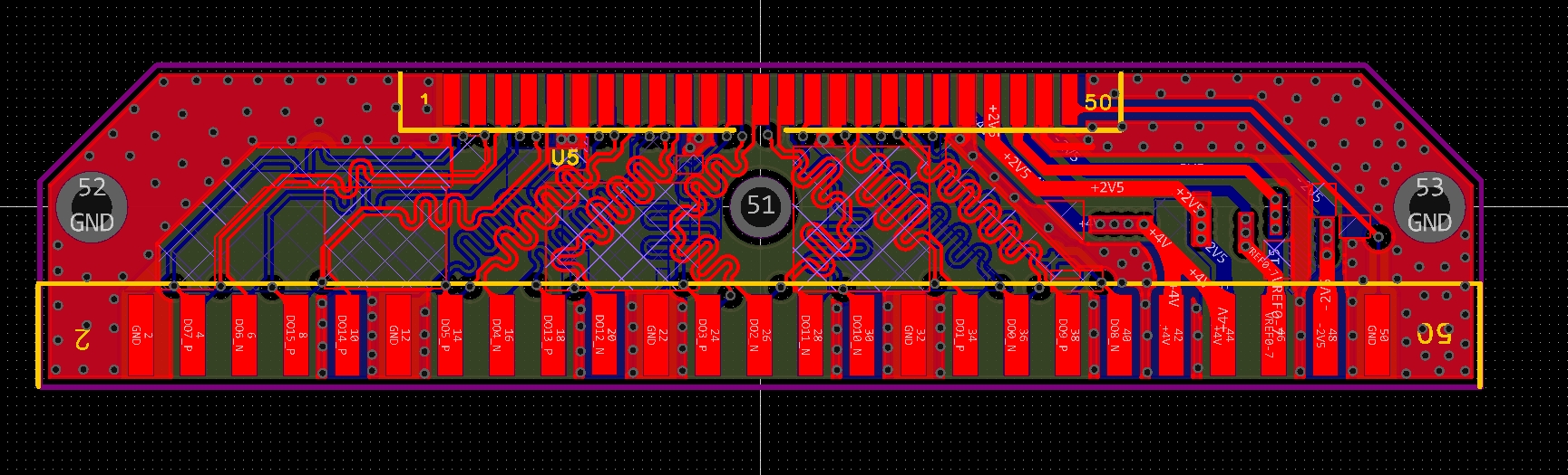
This project is based on the EEVword open-source platform. It features a logic probe designed by the developer, based on the LMH7322 solution and mimicking the architecture of the Rigol PLA2216.
The open-source logic probe

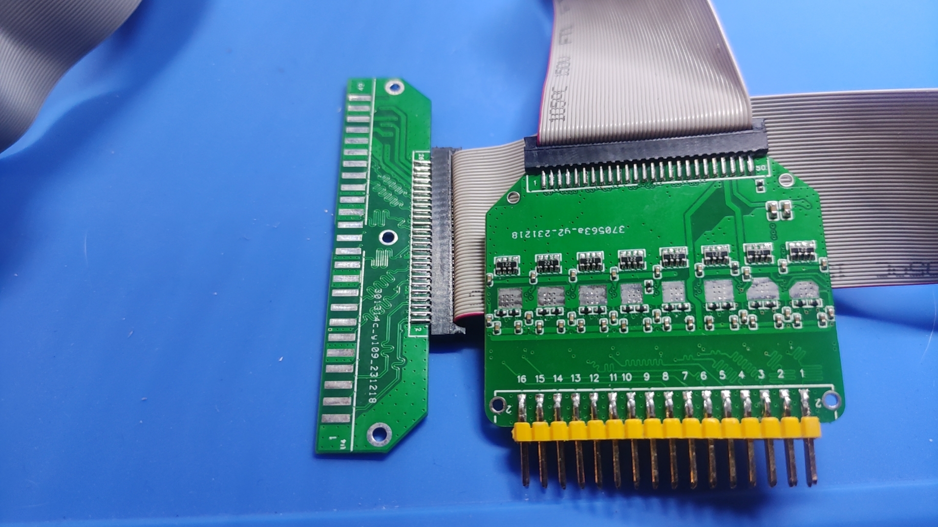
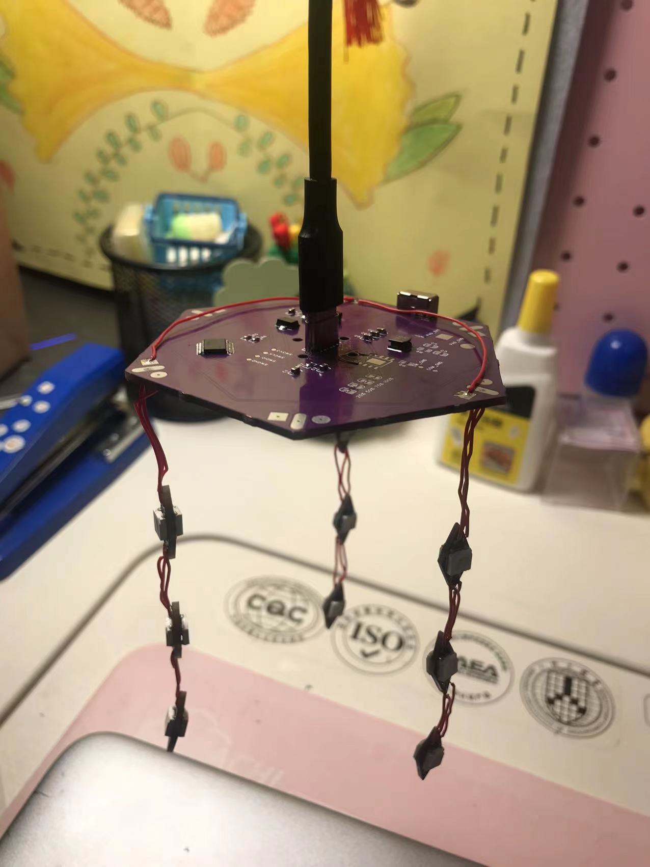
was redesigned using the EEV solution and provided schematic. The PCB
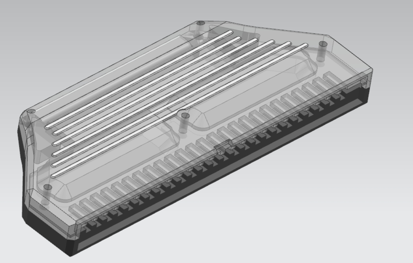
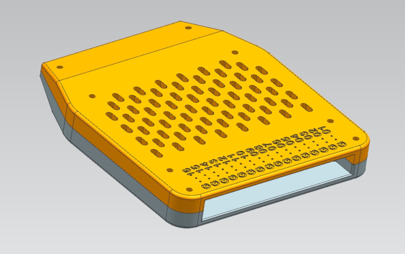
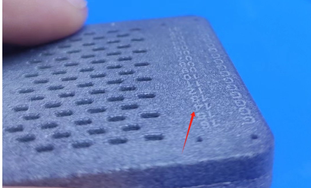
was redrawn using UG, and the SLS nylon shell printed by LCSC 3D Printing
passed self-test and has been verified as usable. However , it experienced
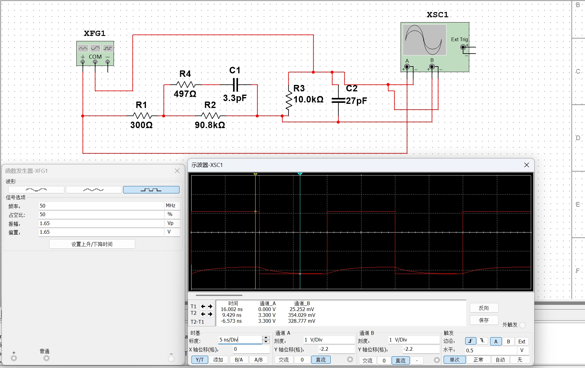
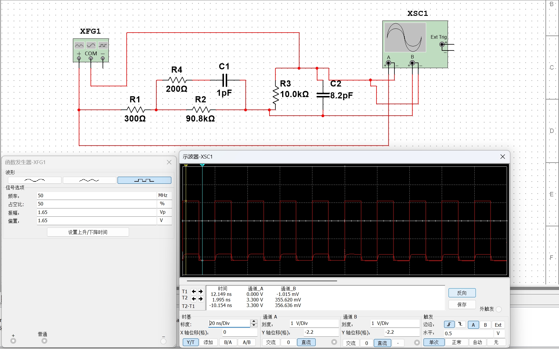
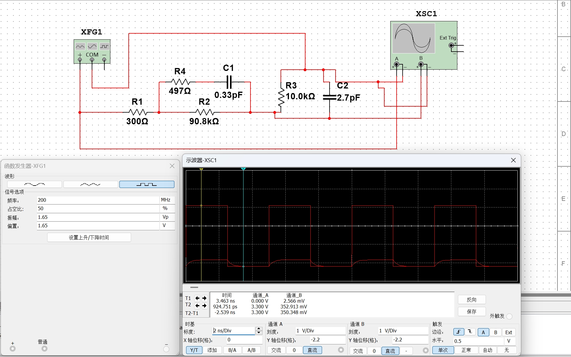
significant overheating during actual use, and the frequency of the test signal should not be too high.
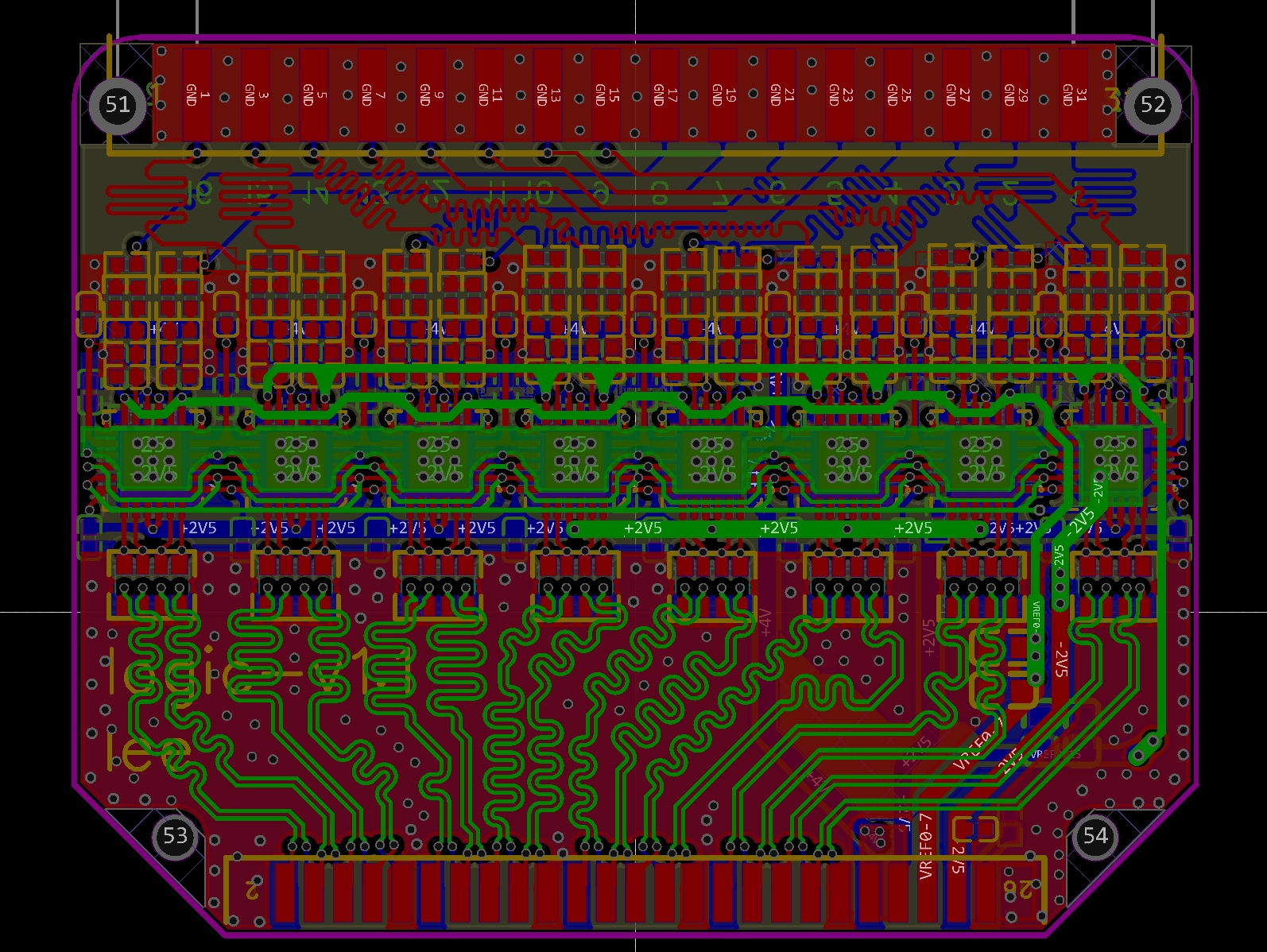
The overall signal lines on the PCB were made to be of equal length. The appearance
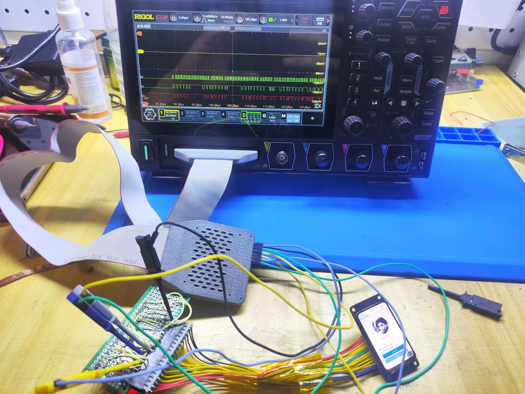
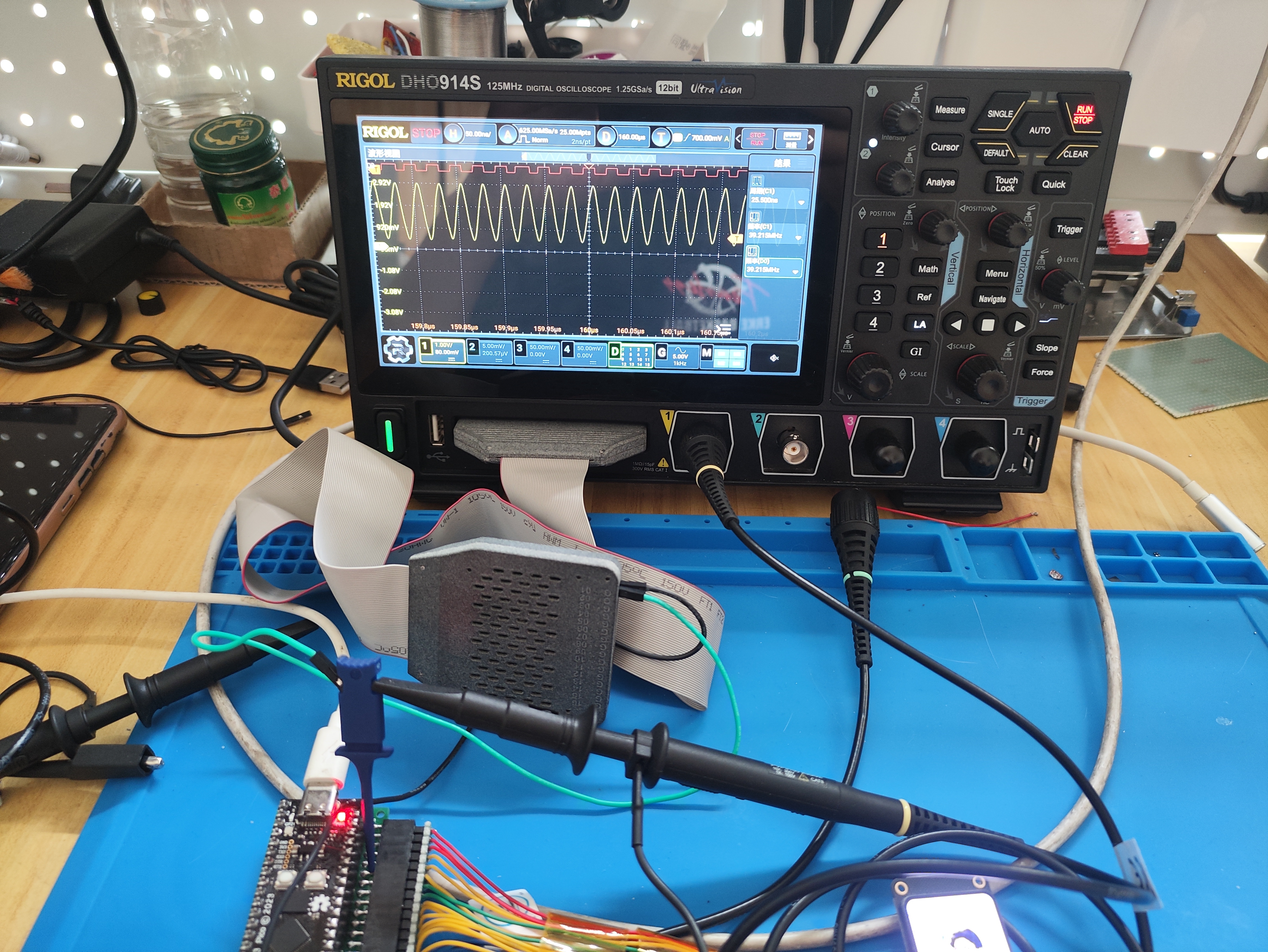
is referenced from the original PLA2216. The SPI 40MHz clock signal of the ESP32-S3

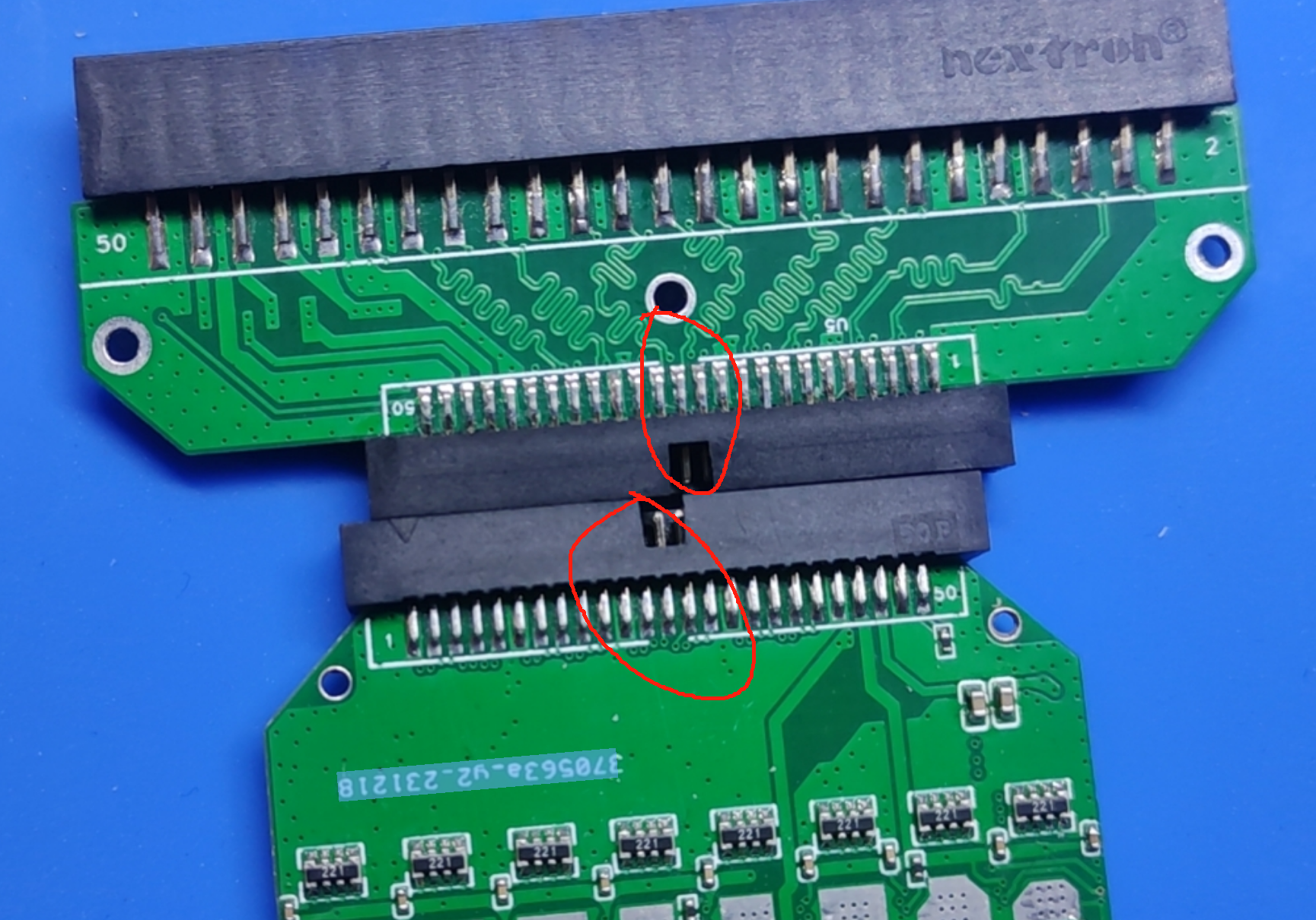
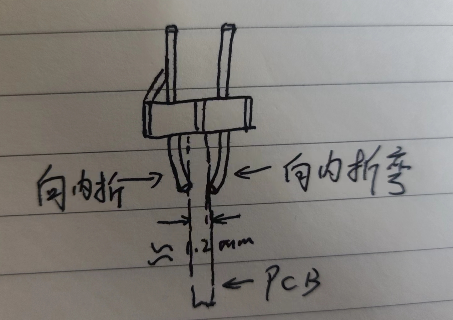
was tested. PCB board design notes: The board thickness must be 1mm. Otherwise, the 1.27mm pitch horn socket cannot be soldered. The adapter board and probe should use the "New Version of Adapter Board" and "New Version of 7322 Probe" respectively. For some accessory names, models, and precautions, please refer to the link: 1.27mm Simple Horn Socket (1.27-50p , no reference): https://detail.tmall.com/item.htm?id=667102167466&spm=a1z09.2.0.0.72b02e8dg2PfdX&_u=dkfq3du1f74 2.54mm pitch cable with nose- mounted female - 50p (no connector) https://item.taobao.com/item.htm?spm=a1z09.2.0.0.72b02e8dg2PfdX&id=564504938654&_u=dkfq3dua925&skuId=3731775526829 FC ribbon cable 1.27mm double-ended, same direction (Note: you need to buy the same direction cable) https://detail.tmall.com/item.htm?id=662516724614&spm=a1z09.2.0.0.72b02e8dg2PfdX&_u=dkfq3du5f05 2*16p, 2.54mm pitch header pins . Some minor details : equal-length wiring, soldering , 1.27mm horn-shaped socket direction, 2.54mm nose-type female header direction , 2x16p pitch, 2.54mm header pin handling , casing modeling . I graduated with a degree in "Mechanical Design, Manufacturing and Automation." A regretful attempt ... Actually, I could have used soldered 1.27mm ribbon cables . I should have bought some longer 1.6mm self-tapping screws. I could have used "recessed and raised lettering" to make the lettering clearer. Bandwidth simulation: 50MHz is okay, 200MHz WTF?!!!! That 's it, as long as it works, I'll just leave it ... If it does n't work , I'll try again . Last - minute cramming is still cramming, at least you, dear readers , judge for yourselves. I'm just a software developer , I have n't studied hardware , I don't know anything about it! This is truly a sign of weakness. Goodbye!


fefeba3ea13c76a11e71b9ec21e763fb.mp4
8e7a2b20ba3e818dd6f5226f2b847df0.mp4
connect-1.stp
connect-2.stp
prb-1.stp
prb-2.stp
967298c3ba56251054b0b47aa9e2faf4.mp4
PDF_MSO5000-DHO900 Logic Probe.zip
Altium_MSO5000_DHO900 Logic Probe.zip
PADS_MSO5000_DHO900 Logic Probe.zip
BOM_MSO5000_DHO900 Logic Probe.xlsx
94252
#Call for Submissions# Colorful Wind Chimes
Create a colorful wind chime-style string light using the Air001 chip and WS2812B.
This project uses the Air001 chip and WS2812B to create a colorful wind chime-style string light. The current version has 3x3 lights, but theoretically it should have 6xN lights. You can extend and add more lights as desired. See the attached video at the bottom for a demonstration.
 
 
Project Introduction:
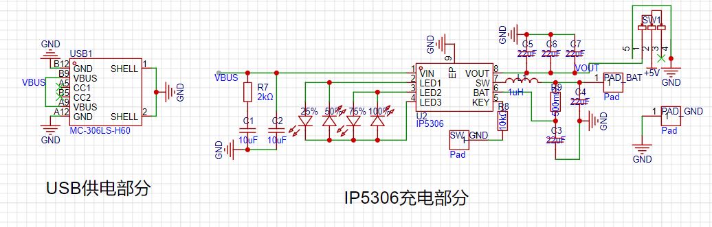
1. A charging circuit is provided (the chip used is IP5306, the reference chip for the MH-CD24 small board).
2. The main controller uses the Air001 chip, but actually uses the PY32F002AF15P6TU, which costs only 5 cents a piece with free shipping.
3. There are no strict requirements for the LDO; I used an H7333-3, but you can modify the circuit diagram and replace it with your own LDO
. 4. The four holes in the middle are for threading a rope to hang it, because there will be no Type-C port when using batteries.
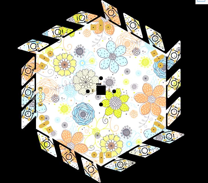
5. The board comes with 6*3 diamond-shaped lights per batch. Cut them yourself; 5 pieces will give you 6*3*5=90 lights, which is 6*15mm long enough.
 
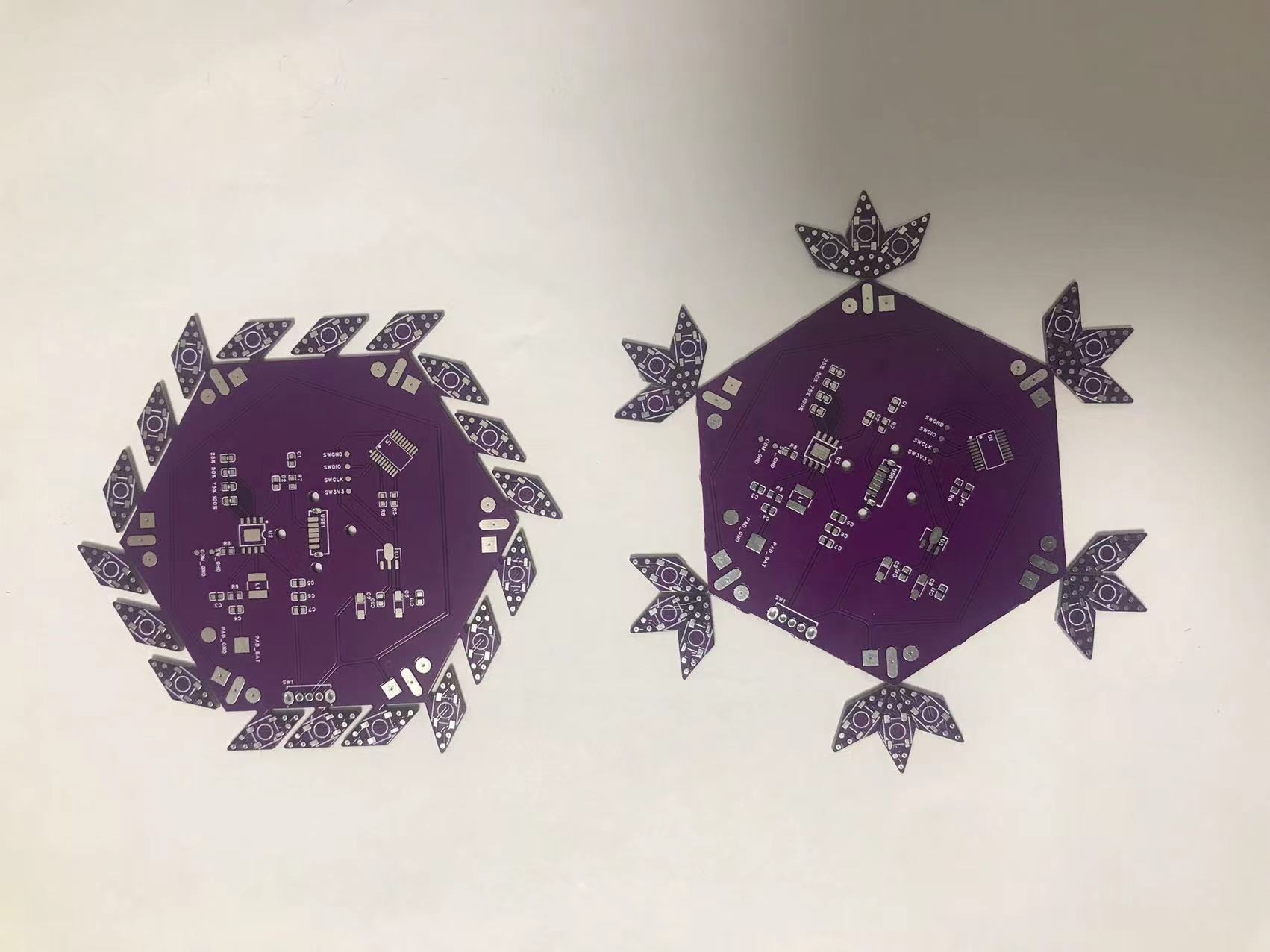
The image on the right is a humorous arrangement; this board is not actually in use.
 
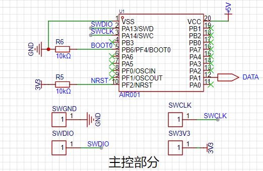
Schematic Introduction:
As mentioned earlier, the PY32 is identical here; the Air001 is only used for schematic drawing.
The Air001 (PY32) is very useful; it only requires two circuits to run (some say one is enough, but this hasn't been tested), a true gem. For
 
the charging part, you can purchase the MH-CD42 or the IP5306 to build your own. (The seller sent the wrong item, which will be added later.)
The LED string part is a bit special because the LEDs need to be cut off, so it was made using a direct PCB design method; there's only one schematic.
For the LDO part, I just used a component I had on hand; a 5V to 3.3V converter should have many options.
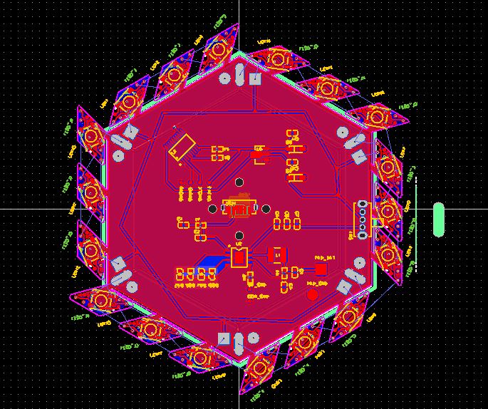
 
Board Introduction:
It's worth mentioning that the three LEDs on each side were cut off with wire cutters; if possible, you can sand the edges.
I've also added a color-printed
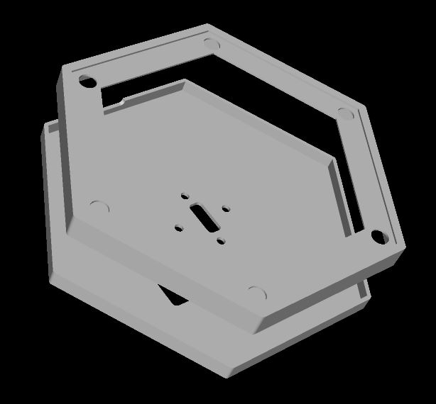
 
3D introduction:
I sketched the 3D shell directly on the Fusion360 (mainly the six rounded corners) and then imported it into LCEDA for DFX drawing.
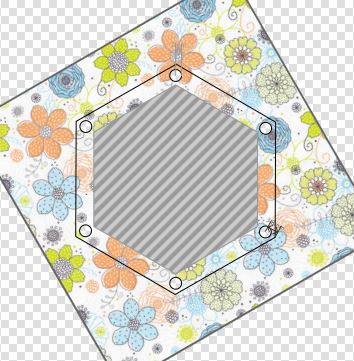
Panel Introduction:
As you can see in the image above, the board frame edges were left.
 
Software Components
: 1. The current default style is a rainbow breathing light
. 2. You can modify it to other styles.
3. Upload the completed code as an attachment.
893551454.mp4
2079423277.mp4
PDF_#Call for Submissions# Colorful Wind Chimes.zip
Altium_#Call for Submissions#Colorful Wind Chimes.zip
PADS_#Call for Submissions# Colorful Wind Chimes.zip
94255
electronic
参考设计图片
×
 
 
Search Datasheet?

Supported by EEWorld Datasheet

Forum More
Update:2026-03-28 12:35:24

EEWorld
subscription
account

EEWorld
service
account

Automotive
development
community

Robot
development
community

About Us Customer Service Contact Information Datasheet Sitemap LatestNews


Room 1530, 15th Floor, Building B, No.18 Zhongguancun Street, Haidian District, Beijing, Postal Code: 100190 China Telephone: 008610 8235 0740

Copyright © 2005-2024 EEWORLD.com.cn, Inc. All rights reserved 京ICP证060456号 京ICP备10001474号-1 电信业务审批[2006]字第258号函 
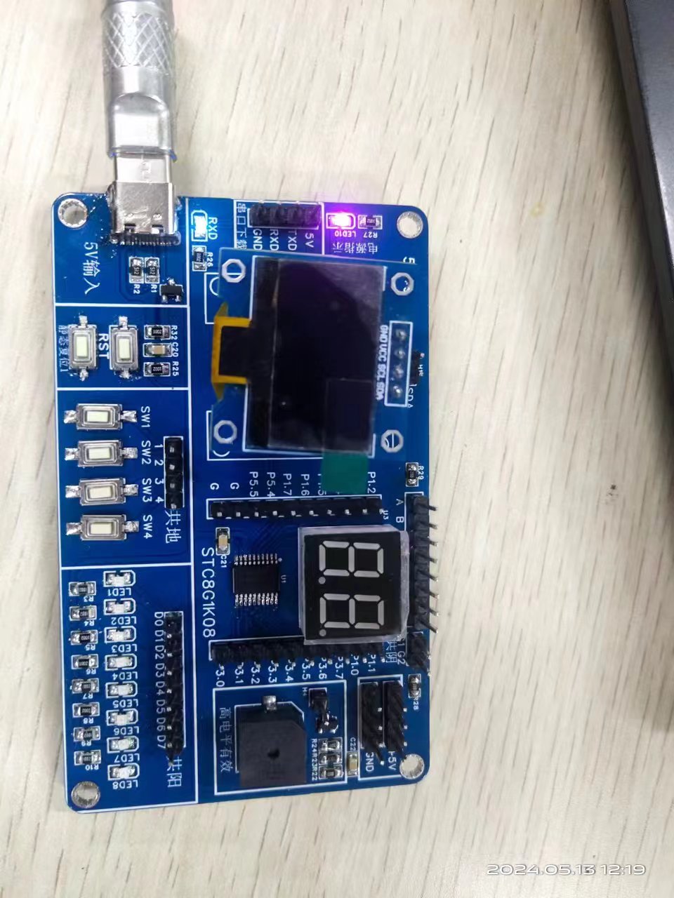
京公网安备 11010802033920号