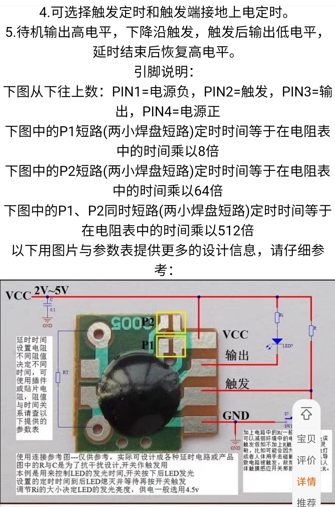
A time-delay relay made with a C005 delay chip
can be independently powered, controlling a voltage exceeding the withstand voltage of a three-terminal regulator.
It can also be grounded to control appliances below 20V without requiring an independent power supply. Replacing it with a 780L5 can achieve over 30V (I have many 1117 chips on hand).
The adjustable resistor in the circuit adjusts the trigger brightness; you can determine the resistor yourself, eliminating the need for soldering an adjustable resistor.
Below are the delay times corresponding to the chip's various resistance values; shorting P1 and P2 doubles the time.

PDF_C005 Light-Controlled Delay Relay.zip
Altium_C005 light-controlled time delay relay.zip
PADS_C005 Light-Controlled Delay Relay.zip
BOM_C005 Light-controlled time delay relay.xlsx
94257
STM32F103RET6 Minimum System Board
The first board I made myself (although it was soldered like a pile of shit)
uses an STM32F103RET6 as its main controller, which is basically fully compatible with the Jiangsu University of Science and Technology's c8t6 board. The programmable
chip has 64k RAM and 512k ROM, which will make running LVGL very convenient.
It has the following advantages:
1. Ideal for beginners to use with two breadboards together.
2. Supports USB, a 5V main power supply module, and a 3.3V backup power supply test module
. 3. Theoretically supports both ST-Link and J-Link debugging (currently tested with ST-Link programming).
4. Almost all usable pins are exposed.
5. BOOT0 and BOOT1 can be switched to 3.3V or ground via jumpers (this is based on the Jiangsu University of Science and Technology board).
6. The schematic uses 24-pin headers or pin headers on both sides. For breadboards, it is recommended to use pin headers and solder them downwards.
A brief introduction to the main buttons:
SW1: RST, reset button .
SW2: Connects to PC13 as a test pin. To test if the program can run, set the PC13 pin high and then press SW2. If LED2 lights up, the soldering is successful and the chip is running normally.
SW3: WAKE UP pin (connects to PA0, used for wake-up).
PDF_STM32F103RET6 Minimum System Board.zip
Altium_STM32F103RET6 Minimum System Board.zip
PADS_STM32F103RET6 Minimum System Board.zip
BOM_STM32F103RET6 Minimum System Board.xlsx
94258
Model airplane accessories
Some homemade accessories for microcontrollers and model airplanes
V1.0: SH1.0; 6pin is an extension for the positioner.
V2.0, V2.1: These are the pad verifications for the network modules used on the two positioners; the complete hardware is under design.
V3.0: DC-DC power supply 12V-5V power supply solution.
IMG_20240616_155704_edit_4982239240753.jpg
IMG_20240616_162141.jpg
IMG_20240501_162835.jpg
IMG_20240616_163005_edit_95301114110987.jpg
PDF_Model Airplane Accessories.zip
Altium_model aircraft accessories.zip
PADS_Model Aircraft Accessories.zip
BOM_Model Airplane Accessories.xlsx
94262
Three-speed control/UV lamp mini fan
Button controls allow for three-level fan speed adjustment;
touch controls
allow the UV curing lamp to be used as a fan.
This project uses three soft-pack polymer lithium batteries (model 502040)
and a C10S011 microcontroller. The module includes the power chip and microcontroller, making it inexpensive.
It utilizes an LP28057A power management chip to charge the lithium batteries. The
UV light
fan is 7W, with dimensions of 40*40*20mm, a hole spacing of 32mm, and M2.5 screw holes.
The cost is 45 yuan.
Your suggestions are welcome; I will continuously improve
and update it. The project also includes improvements to the diode (a small heat-generating component) and fixes the issue of the UV light indicator light not lighting up. (
Demonstration video
(open source) - Mini Fan, High-Performance Fan, UV Curing Lamp - Bilibili)
PDF_Three-speed control - UV lamp mini fan.zip
Altium 3-speed control UV lamp mini fan.zip
PADS_Three-speed control_UV lamp mini fan.zip
BOM_Three-speed control_UV lamp mini fan.xlsx
94264
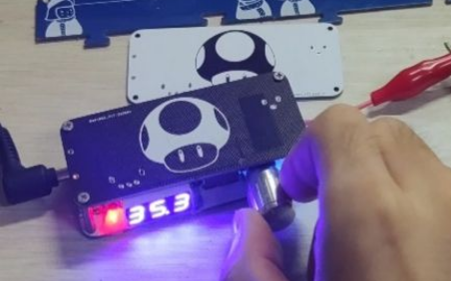
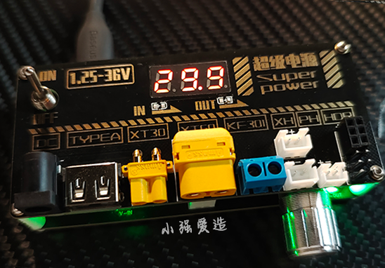
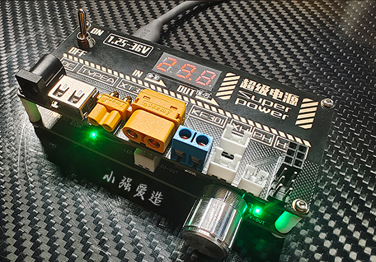
Multi-functional desktop adjustable power supply
Suitable for DIY enthusiasts, intended for use as a test power supply. Includes almost all commonly used interfaces. Please note that it cannot be used at high power.
Modified from project: Red Mushroom Desktop Power Supply MINI Version
================================================================


================================================================================
Bilibili video:
Modifications to the open-source multi-functional adjustable desktop power supply "Xiaoqiang
": 1. Added a top plate with immersion gold decoration; even the neighbor's kids will be envious!
2. Added commonly used connectors to the top plate for easier debugging; no need to search for adapters everywhere.
3. Added mounting holes for the voltmeter; changed from side mounting to top mounting.
4. The top and bottom plates use XH2.54 connectors; 10cm pre-made cables are sufficient.
5. Added indicator light output interfaces to the top plate. If you don't mind too much brightness, you can solder only resistors to the bottom plate, connect the XH2.54 cables to the top plate, and solder the indicator lights to the top plate. If you think the lights are too bright, don't solder the LEDs to the top plate; adapter cables are also optional.
6. Added a master control switch
. Please purchase the interfaces used for the top plate according to the reference price table or the 3D drawing. Due to the group member's test sample not passing the review, the board can only be disassembled for manufacturing.
Please do not mistakenly buy DC002; purchase DC00. 5. Purchase a 0.28-inch three-wire meter head.
I recommend immersion gold for the top plate and tin plating for the bottom plate. Board thickness is 1.6. Customer code 5x5, designated QR code.
Enjoy...^-^...
Video_1717434699264.mp4
PDF_Multifunctional Desktop Adjustable Power Supply.zip
Altium_Multi-functional Desktop Adjustable Power Supply.zip
PADS_Multi-functional Desktop Adjustable Power Supply.zip
BOM_Multi-functional Desktop Adjustable Power Supply.xlsx
94265
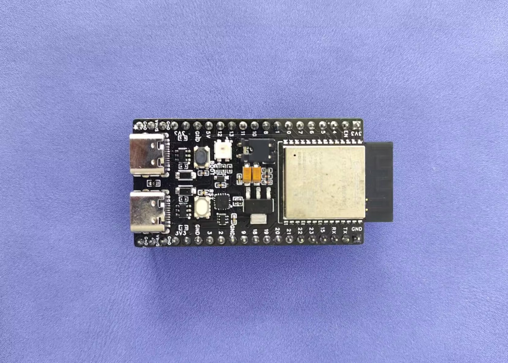
ESP32-C6-WROOM Development Board
Overview: Based on the official development board, Espressif's first SoC supporting Wi-Fi 6 integrates 2.4 GHz Wi-Fi 6, Bluetooth 5 (LE), and the 802.15.4 protocol.
1. Project Description:
This development board is only for testing program download; all other aspects are for testing.
Referencing the official development board, it has more power pins than the official board; it uses the CH343P to reduce layout area; it includes an RTC pin; the left Type-C port is for the chip's USB, and the right port is for UART, whereas the official board is the opposite.
2. Physical Sample Image
and Silkscreen Marking: PDSU: Pingdingshan College, 010424: Design completed on January 4th, 2024.

3. Other
Work: I've become lazy; I'll add more later when I have time.
PDF_ESP32-C6-WROOM Development Board.zip
Altium_ESP32-C6-WROOM Development Board.zip
PADS_ESP32-C6-WROOM Development Board.zip
BOM_ESP32-C6-WROOM Development Board.xlsx
94266
Environmental parameter detection plus turbine absorption temperature
After learning STM32 for the first time, I completed a small project by making my own PCB. Due to the assignment requirements and the fact that I often inhaled solder paste fumes while soldering, I thought of using a turbo fan to suck away the solder fumes through a pipe.
It uses an STM32F103C8T6 chip and an external soft-pack lithium battery. The charging chip is an IP5306, with a built-in boost circuit providing a 5V output to meet the normal operation of the turbine fan. The TC118S motor driver chip offers excellent cost-effectiveness and a maximum current output of 2A. This module will be well-suited for training ADC sampling, single-bus communication (DS18B20), OLED screen I2C communication, and PWM output. Further improvements are planned.
3d.rar
Program code.rar
Serial port software.rar
VID_20240613_124954(1).mp4
PDF_Environmental Parameter Detection Plus Turbine Absorption Temperature.zip
Altium_Environmental Parameter Detection Plus Turbine Absorption.zip
PADS_Environmental Parameter Detection Plus Turbine Absorption Temperature.zip
BOM_Environmental Parameter Detection and Turbine Absorption Temperature.xlsx
94267
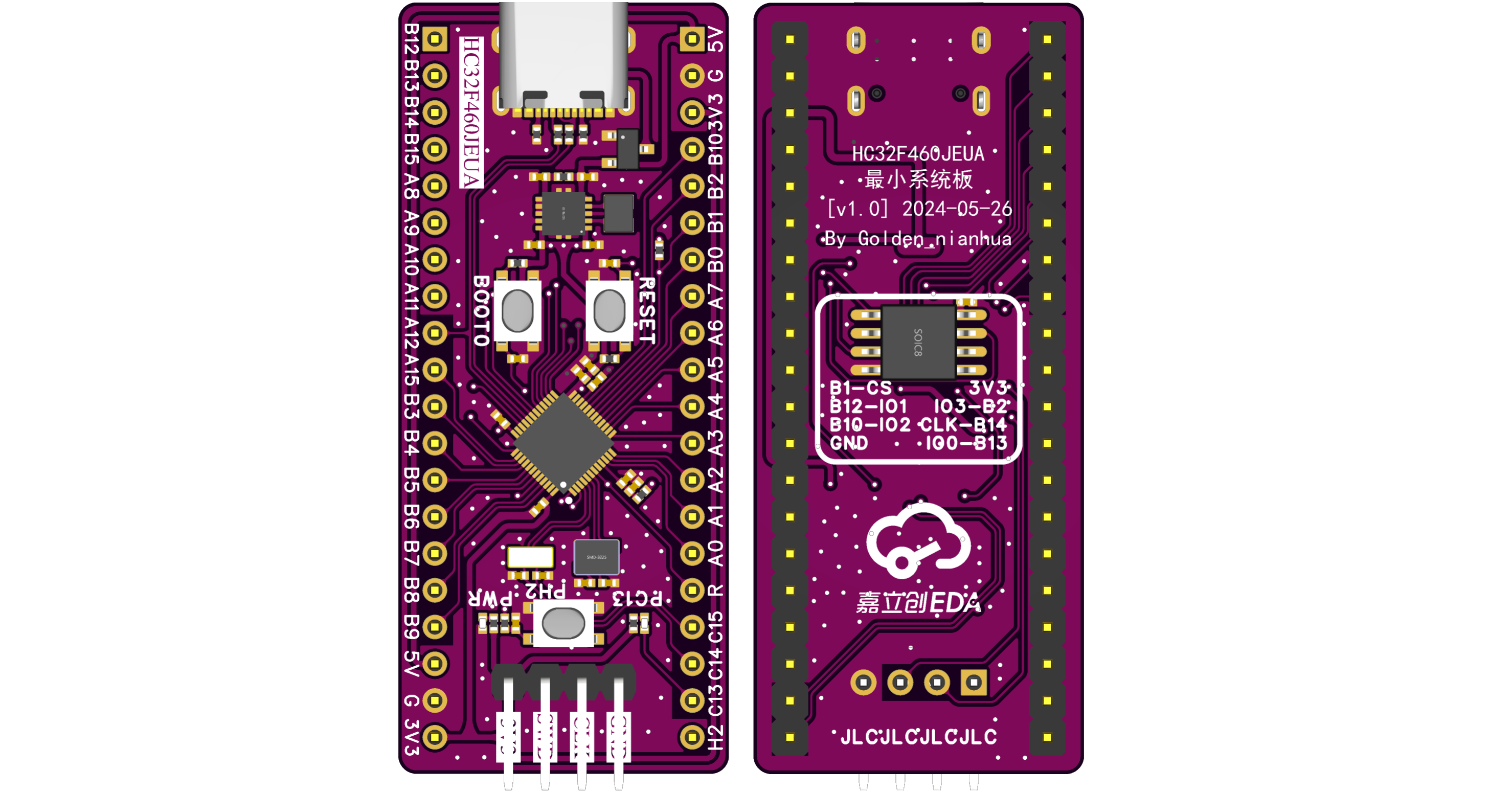
HC32F460JEUA Minimum System Board
HC32F460JEUA Minimum System Board
I. Introduction:
HC32F460JEUA minimum system board, dimensions 53.36mm x 22.86mm (2100mil x 900mil), pin pitch 15.24mm (600mil).
TPS63001 buck-boost switching power supply provides 3.3V power. CH213K ideal diodes provide reverse polarity protection. Optional QSPI FLASH on the bottom panel
includes a reset button, BOOT0 (MD) button, user button -PH2, and user LED -PC13.
See schematic diagram for pin connections. II. Appearance Diagram.
III. Issues
: None.
IV. Update:
v1.0-20240404 (
First Version)
PDF_HC32F460JEUA Minimum System Board.zip
Altium_HC32F460JEUA Minimum System Board.zip
PADS_HC32F460JEUA Minimum System Board.zip
BOM_HC32F460JEUA Minimum System Board.xlsx
94268
DAPLinkMini
This is a copy of https://oshwhub.com/ll1234567/daplink-down, with some hardware points optimized, an outer casing added, some pins modified, and a few optional hardware components added. It has been verified and is completely reproducible.
First, here's the finished PCB. It's a free gold-plated 4-layer board from LCSC (JLCSC NB).
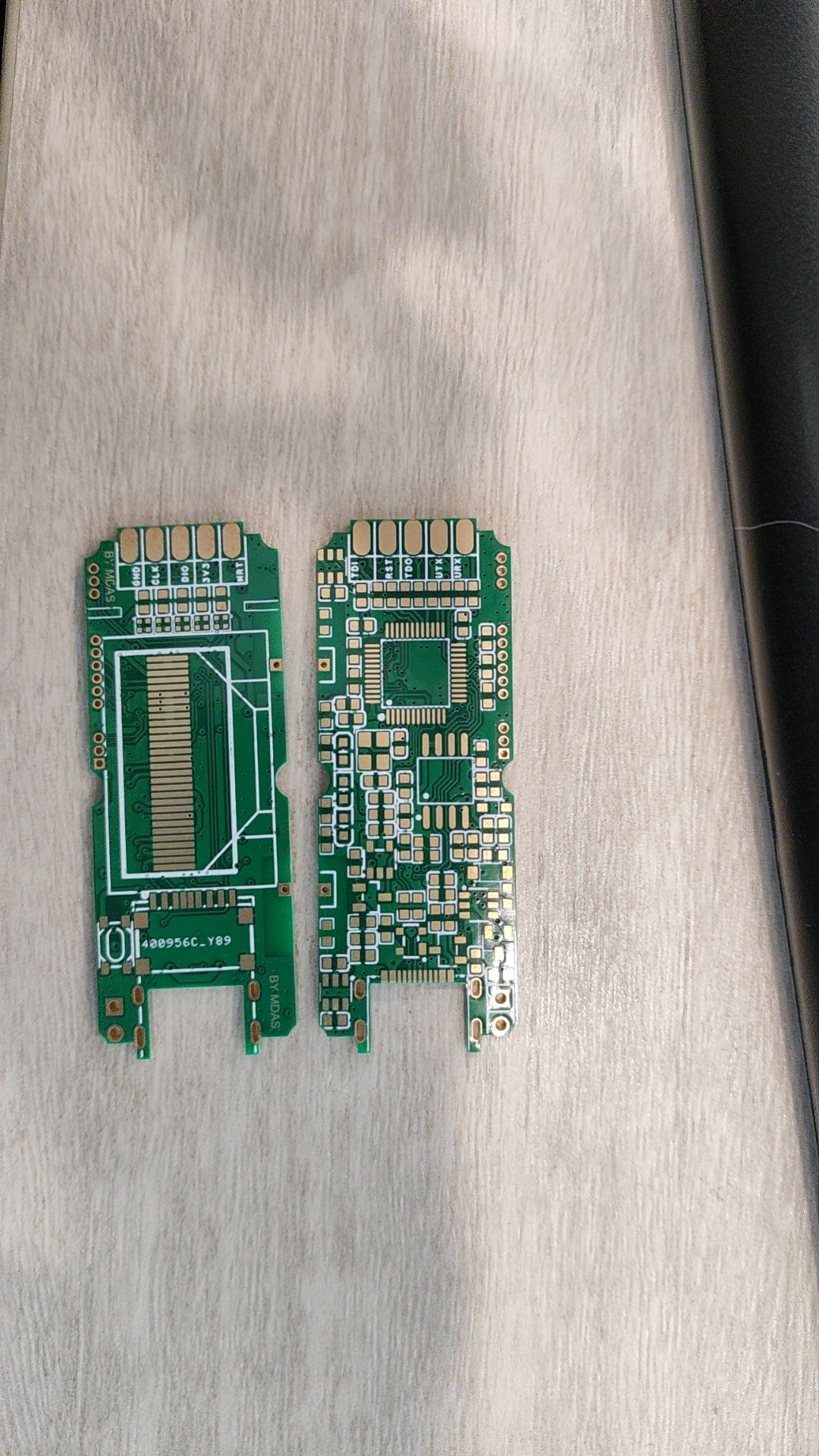
My J-Link's USB port broke, so I wanted a working debugger. I also occasionally need to download files offline. I found the original author's project, which seemed perfect for me, so I replicated it.
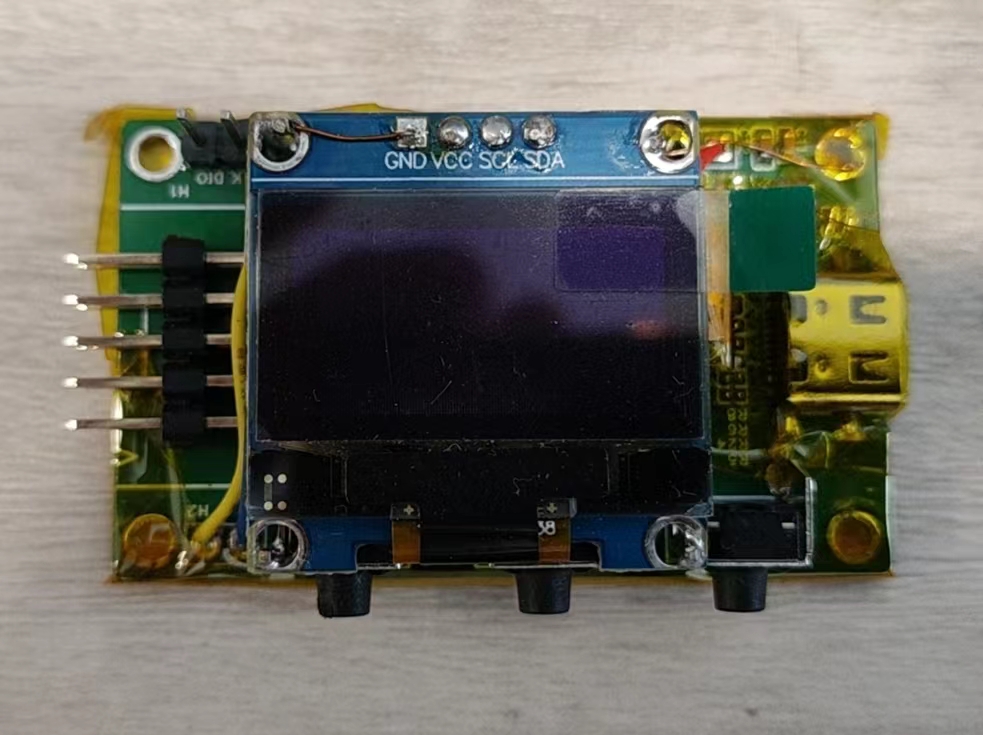
Since I couldn't find the original OLED separately, I just used an extra module from before, modified it, did some wire work, and made this.
Program burning file.zip
DapBootLoader.zip
DapGD32HID.zip
PDF_DAPLinkMini.zip
Altium_DAPLinkMini.zip
PADS_DAPLinkMini.zip
BOM_DAPLinkMini.xlsx
94269
electronic


 京公网安备 11010802033920号

 HDSP-333Y-GI200


