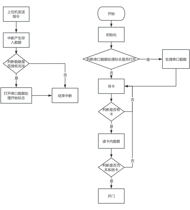
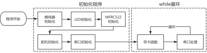
This paper introduces the design of an access control system based
on the RC522 RF chip. The system combines RF identification with IC card technology. Using an STM32F103C8 as the main control chip, it communicates with the MFRC522 chip via SPI communication technology to identify and read IC card sector data to determine card access authorization. A Bluetooth chip is integrated to communicate with a host computer, enabling the host computer to customize parameter settings for the access control system, as well as control functions such as mode switching, password unlocking, and adding and deleting IC cards. The system also integrates card writing and reading, improving operational convenience. Overall Design Scheme Block Diagram Schematic Diagram Design Instructions: Please provide schematic diagrams of the modules in the design, preferably along with physical images. Each module needs to be described. If no design is required, please indicate the source of the diagram. PCB Design Notes : A no-copper zone must be set up at the 2.4G antenna location, and GND vias should be placed around it to prevent signal interference. Software Description: The code snippet shown is not the complete code. It includes the main logic and approach of the program; the rest is driver code for some components. Generally, this can be found online and customized, so it will not be elaborated on here. In addition, this system also has a host computer developed using the WeChat Mini Program development platform. Because I used the ECB01-C Bluetooth chip, the manufacturer's official website has documentation and sample code for their Mini Program. Using the official sample code with some modifications, it's very easy to operate, so it won't be included here. Software overall design framework , system main program, RF module program design, serial communication program design code block: // Main function area #include "stm32f10x.h" // Device header #include "led.h" #include "buzzer.h" #include " usart.h " #include "spi.h" #include "rc522.h" #include "Delay.h" #include "lift.h" #include "timer.h" #include "server.h" #include #include int main(void){ buzzer_init(); // Buzzer initialization NVIC_PriorityGroupConfig(NVIC_PriorityGroup_2); // Interrupt settings LED_Init(); // Led initialization TIM2_PWM_Init(200-1,7200-1); // PWM output initialization Servo RC522_Init(); // rc522 initialization usart_init(9600); // Serial port initialization, parameter is baud rate buzzer(2,100,100); // Initialization complete prompt, buzzer sounds twice while(1) { if(mainmode==1){Data_analysis();} // Automatic card search usart_handle(); // Serial port debugging } } // Card search function char rc522_read(u8 Sector,u8 block){ //testkeyAB(Sector,block);//Verify AB key rc522_read(Sector,block); if(block==0){//block 0 if(PcdAuthState(PICC_AUTHENT1A,Sector*4+block,KEY_A,SN)!=MI_OK){LED_star1();return 1;}//Verification, if it fails, the LED blinks if(PcdRead(Sector*4+block,Data0)!=MI_OK){return 1;}//Read block //Send data to serial port Serial_SendByte(0xA0); Serial_SendArray(Data0,16); Serial_SendByte(0xAF); } else if (block==1){//block 1 if(PcdAuthState(PICC_AUTHENT1A,Sector*4+block,KEY_A,SN)!=MI_OK){LED_star1();return 1;}//verification, if it fails, the LED blinks


if(PcdRead(Sector*4+block,Data1)!=MI_OK){return 1;}//Read block
//Send data to serial port
Serial_SendByte(0xA1);
Serial_SendArray(Data1,16);
Serial_SendByte(0xAF);
}
else if (block==2)//Block 2
{
if(PcdAuthState(PICC_AUTHENT1A,Sector*4+block,KEY_A,SN)!=MI_OK){LED_star1();return 1;}//Verify, if it fails, the LED blinks
if(PcdRead(Sector*4+block,Data2)!=MI_OK){return 1;}//Read block
//Send data to serial port
Serial_SendByte(0xA2);
Serial_SendArray(Data2,16);
Serial_SendByte(0xAF);
}
else if(block ==3)//Block 3
{
if(PcdAuthState(PICC_AUTHENT1A,Sector*4+block,KEY_A,SN)!=MI_OK){LED_star1();return 1;}//Verification, if it fails, the LED blinks
if(PcdRead(Sector*4+block,Data3)!=MI_OK){return 1;}//Read block
//Send data to serial port
Serial_SendByte(0xA3);
Serial_SendArray(Data3,16);
Serial_SendByte(0xAF);
}
else {return 0;}
return 0;
}
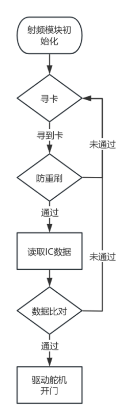
/*Description: Card swipe anti-duplicate
* (1) Record the ID after the first card swipe. If it is the same after the second swipe, no operation is performed. If the data is incomplete, continue reading.
* (2) If the card leaves, it can be swiped again, or the card can be changed.
* Function name: cardre()
* Input: None
* Return: Return 1 means card search failed or anti-duplicate swipe; return 0 means the card can be read after the first swipe
. * /* Call: Internal call
*/
char cardre()
{
u8 i = 0;
if (rc522_findcard() == 1) // Card search failed or card has left
{
findcardnum = 0;
return 1;
}
// Card search successful, first swipe and record ID
if (findcardnum == 0)
{
for (i = 0; i < 4; i++)
{
newSN[i] = SN[i];
}
findcardnum = 1; // Second or more swipes flag
return 0; // Allow reading data
}
// Second or more swipes
for (i = 0; i < 4; i++)
{
if (newSN[i] != SN[i]) // If any digit is different from the original card ID, it means a new card has been input
{
for (i = 0; i < 4; i++) // Copy the new card ID
{
newSN[i] = SN[i];
}
buzzer(2,100,100);
return 0; // New card allowed to be swiped
}
}
return 1; // Anti-repeated swiping
}
// Data comparison, open door on success, buzzer feedback on failure, return 1 on failure, return 0 on success
u8 Data_Comparison()
{
u8 y=0;
u8 i;
for(i=0;i<16;i++){if(Data0[i]!=cardkey03[i]){y++;}}
if(y!=0){buzzer(2,300,300);return 1;}else{buzzer(1,500,500);opendoor();return 0;}
}
// Card search function
void Data_analysis()
{
if(cardre()==1){return;} // Prevent duplicate card searches
if(rc522_read(sector,0)==1){return;} // Data is filled into data0
if(Data_Comparison()==1){return;} // Data comparison, open door if successful, buzzer feedback if unsuccessful
clear(); // Clear card swiping cache, clearing any information left over from the last card swipe
}
Physical demonstration instructions
1. Power on startup: The 3.3V power indicator light illuminates, indicating normal power circuit startup. The buzzer beeps twice, indicating system initialization is complete. As shown in Figure 5-4:
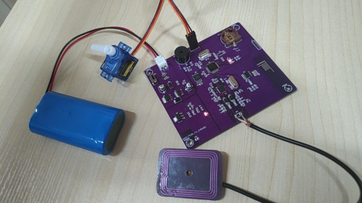
Figure 5-4 System startup
2. Swipe the system's IC card: Place the IC card at the antenna. The system recognizes the card, LED2 lights up, the buzzer sounds continuously, and the servo rotates in reverse for 300ms to indicate door opening. After 3 seconds, the servo rotates forward for 300ms to indicate reverse rotation. As shown in
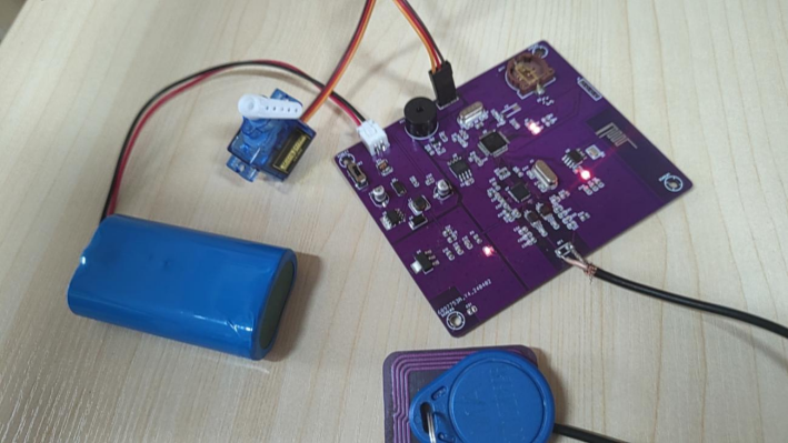
Figure 5-5: 3. Swiping a
non-system IC card: Place the IC card at the antenna. The system will recognize the card, LED2 will light up, the buzzer will beep twice, and the servo will not move. As shown in Figure 5-6: Notes on

swiping a non-system card : The antenna needs to be externally connected. I have specifically provided an external antenna, allowing for free adjustment of antenna parameters. If you need the information, please leave a comment. I will release my antenna information later.


 京公网安备 11010802033920号

 TKJ0W12B8MSN


