# Project Name:
**Smartphone Project Based on the Taishanpai Development Board**
# Project Introduction:

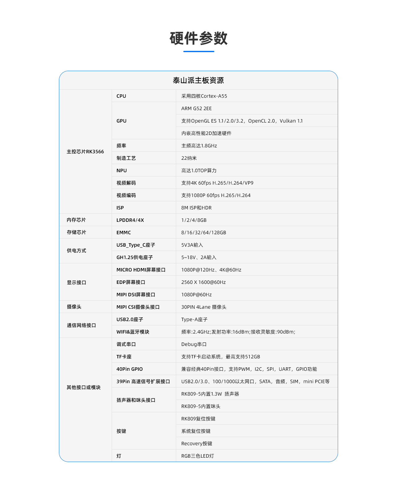
This smartphone project is based on the LCSC Taishanpai development board and training camp. It aims to utilize the powerful performance and rich interfaces of the Taishanpai to create a powerful, compact, and exquisite smartphone. The Taishanpai development board uses the RK3566 core, is equipped with 2GB DDR4 and 16GB eMMC, and provides a rich set of interfaces, providing a solid foundation for the smartphone project development.

# Consumables Request
: - One i9-10900k (32GB + 2TB + RTX4060)

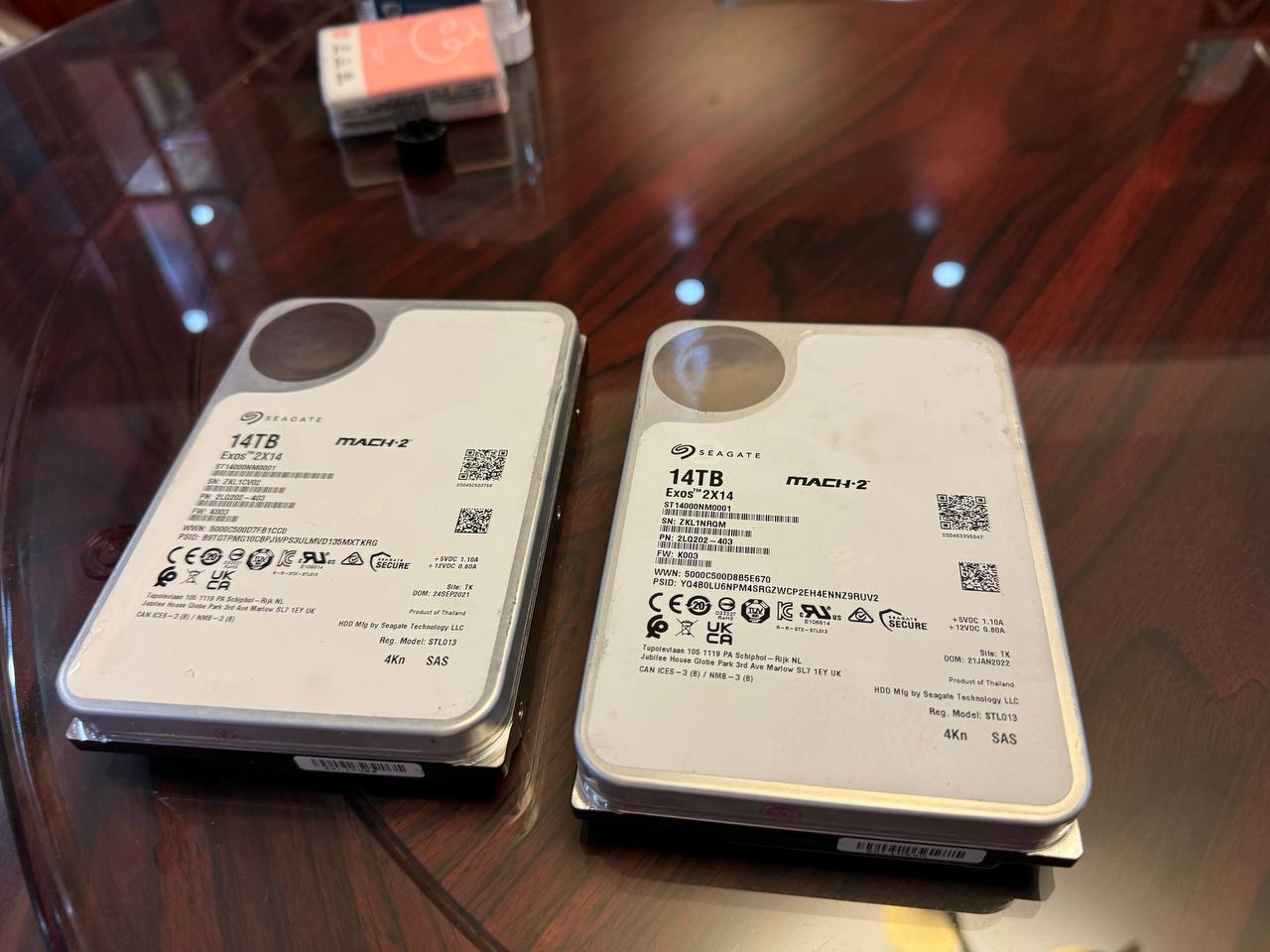
- Two Seagate 14TB HDDs
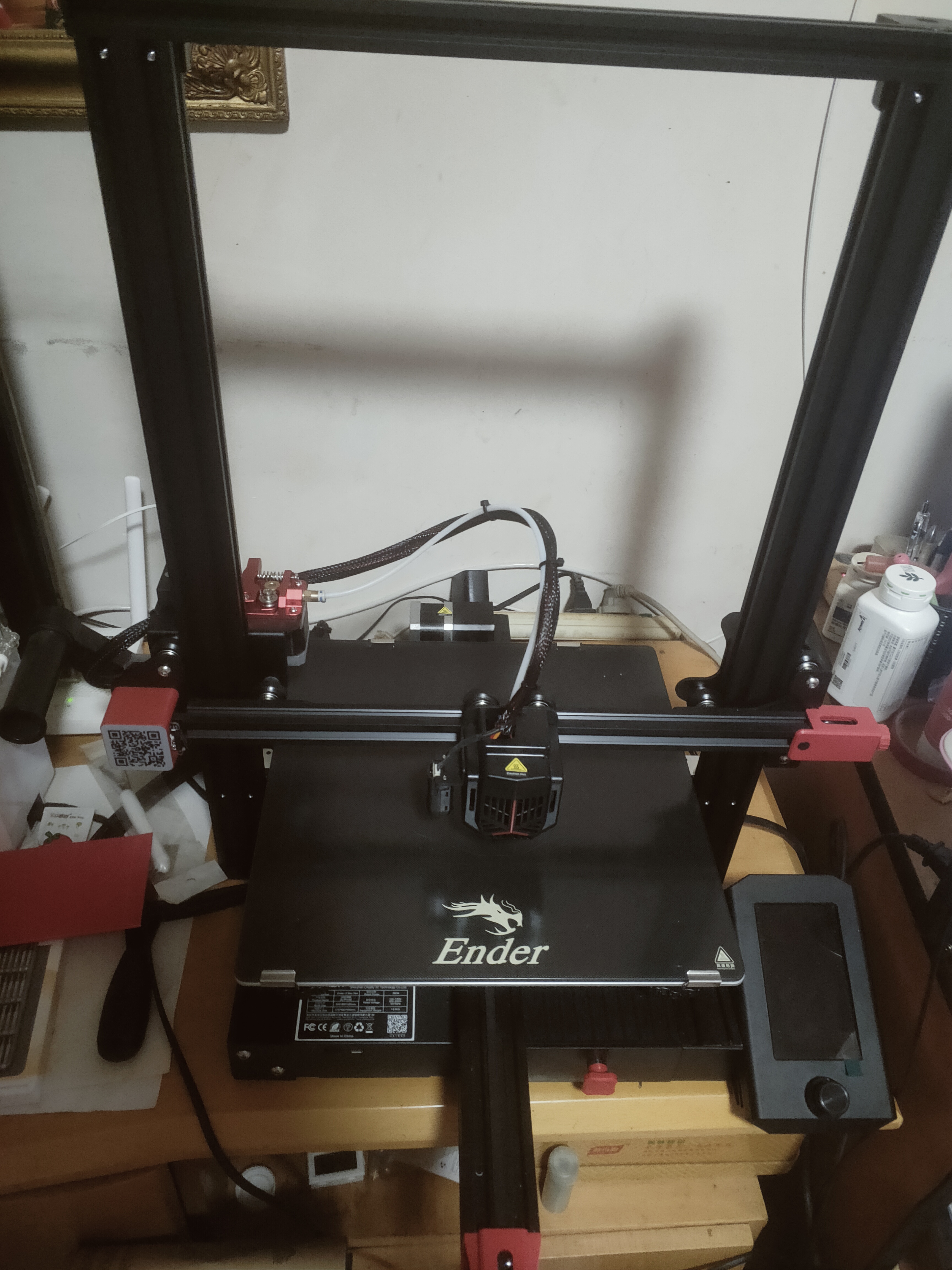
- One Creality 3D printer (Ender3MaxNeo)
- Several PCB freebie coupons, color screen printing coupons, 3D printing coupons, and SMT freebie coupons. (Note:
I don't have these; I'll have to ask LCSC for them!) ๑乛◡乛๑

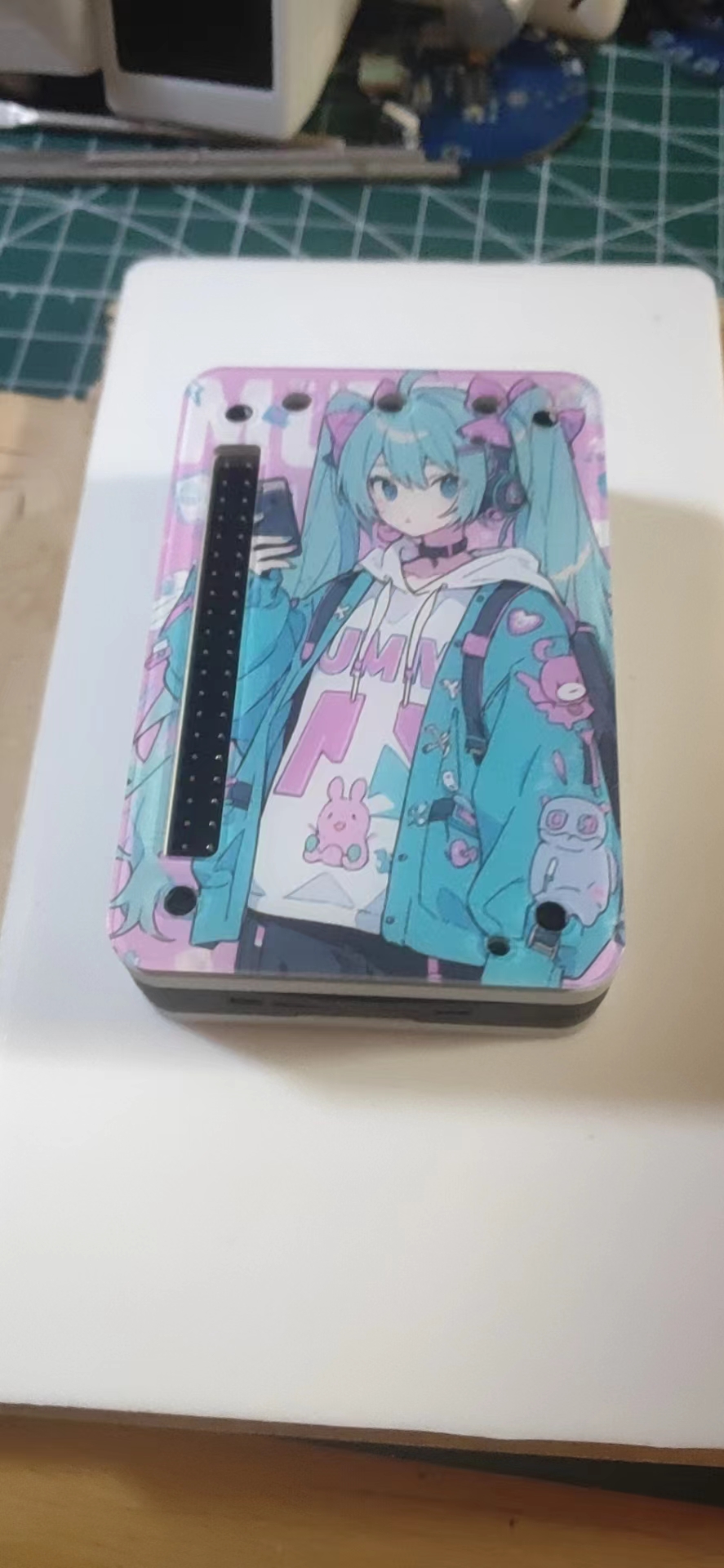
# The Taishanpai shell
uses two modification schemes: `colored acrylic` and `metal CNC`.
The CNC was obtained for free from files shared by a master in a WeChat group. The panel is modified from the [Taishanpai CNC Shell and Taishanpai Panel](https://oshwhub.com/23studio/deng-tiao-mian-ban-ji-tai-shan-pai-mian-ban) by the master in the square 23studio.
The 3D sandwich can shrink by `0.1%` in actual testing. I don't know if it's because nylon expands a little after printing. During assembly, the edges will curl up slightly.

This freebie of LCSC CNC machining, panel printing, and 3D printing is simply amazing!


Here's the result:

## A little extra : Those of you who
got the free panel printing,

can guess how many projects are included in this project?
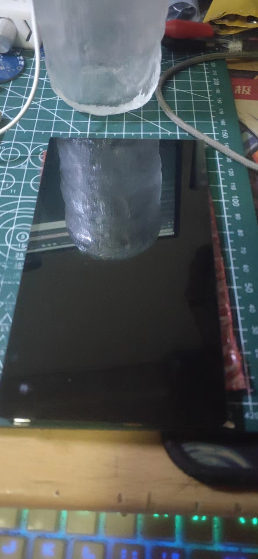
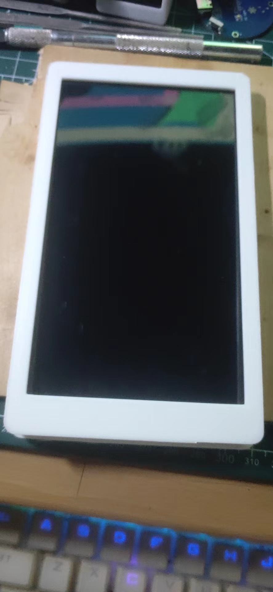
# The screen
is a 6-inch cat-themed screen (bought for 39 RMB on Xianyu, a steal!)
# Schematic analysis (in the spirit of getting freebies)
## Screen Adapter Board:
The adapter board solution adopts the open-source project [Taishan Pie 6-inch Screen Adapter Board [Luxury Version]](https://oshwhub.com/fengmoxi/taishan-pie-6-inch-screen-adapter-board-moat-version) by the open-source expert Fengmoxi.
Based on the work of the expert [leefei](https://oshwhub.com/leefei/taishan-pie-6-inch-display-screen-adapter-board), I added level conversion, impedance matching, and other functions.

Similarly, based on Fengmoxi's work, I changed the four-layer board to a two-layer board (it's so satisfying to directly copy someone else's homework); ~~At the same time, I replaced the mysterious package `OK-06F024-04` with the common `CONN-SMD_24P-P0.40_XKB-CONNECTIVITY_X0400FVS-24-LPSN`. ~~Brothers, I made a mistake, this change doesn't work at all. (Re-producing the PCB) **o(╥﹏╥)o**
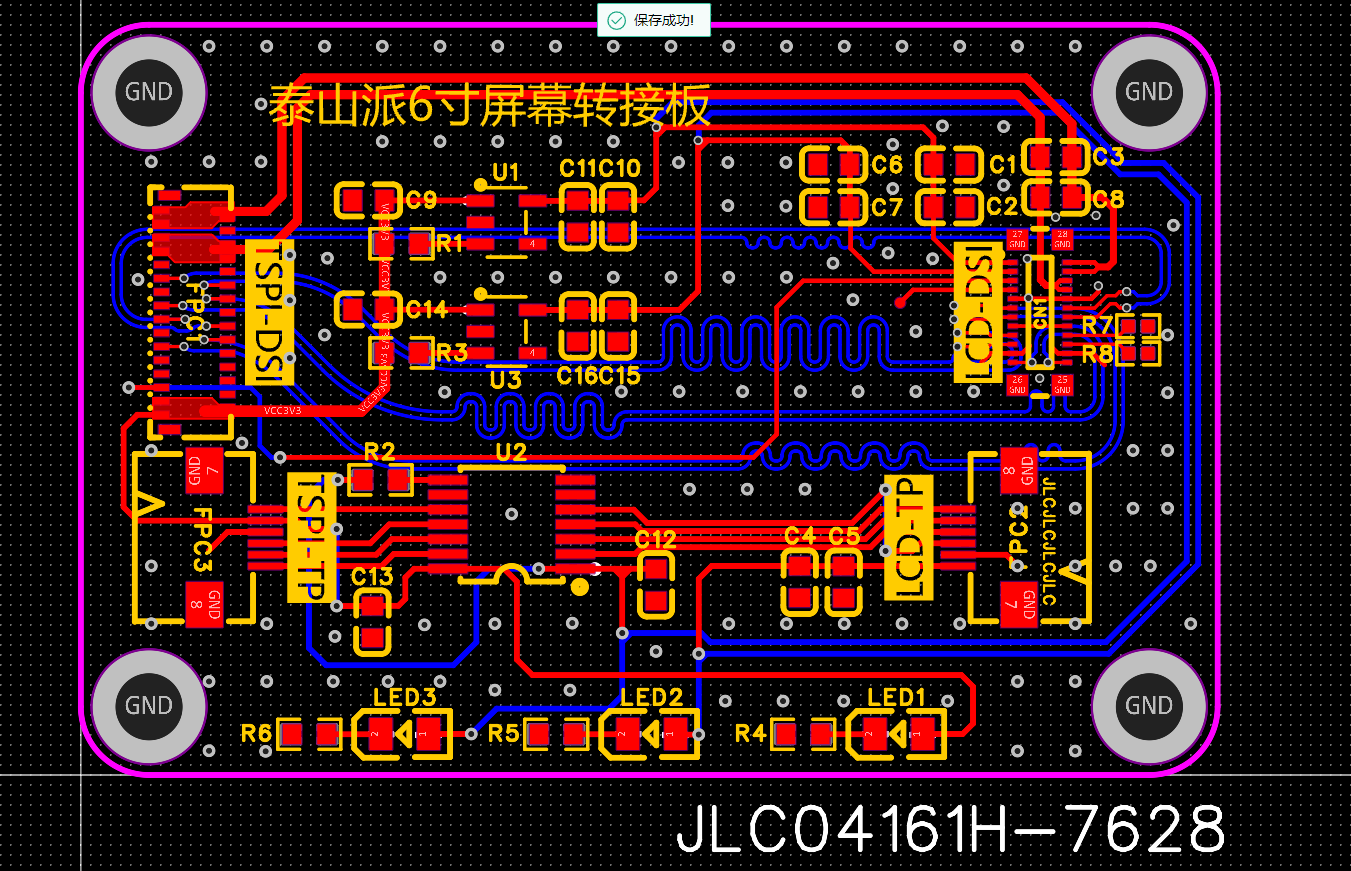
To make it easier for everyone to avoid displaying the customer code during PCB prototyping, I've added the character for adding the customer code at a specified location below the FPC connector. When you're making your PCB, simply add the note: `Custom code added at specified location, no need to confirm production draft`. You can directly enjoy the benefit of a clean PCB prototyping for free (again, thanks to LCSC for their support).
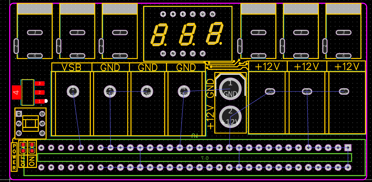
## Power Supply Board:
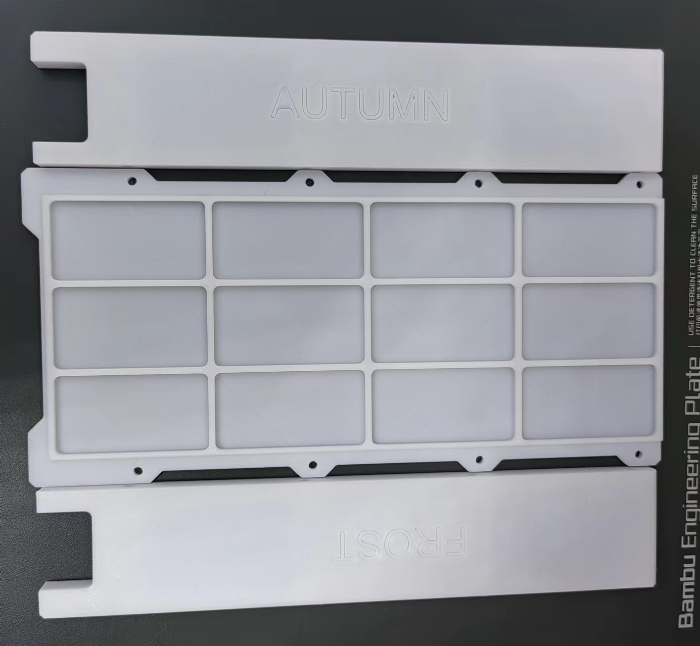
The power supply board solution was quite a coincidence; I discovered it while chatting with a friend in a WeChat group (Note: LCSC development board CNC expert), yes! The same expert who led everyone to get free CNC machining
has actually set his sights on FrostAutumn's [【霜秋凛然FRPS】Plug-and-play Server Power Supply Cage](https://oshwhub.com/frostautumn/re-cha-ba-csps-dian-yuan-bei-ban_copy) project ^_^
The Taishanpai supports 12V power input, and this project's adapter board happens to have four 12V outputs, NICE; so let's just use it out of the box.
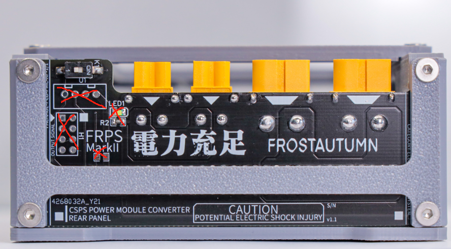
However, since it directly supplies power to the Taishanpai, the two wiring ports and indicator lights (already provided on the power supply) in the picture above are not very useful. So after discussing with the expert, the final modification plan is to remove these unnecessary functions, increase the board's space, and replace all two small `XT30` connectors with larger `XT60` connectors. Now we have four unified 12V output interfaces.
Below is the modified schematic and PCB:


I spent the next two days browsing Xianyu (a Chinese online marketplace) and stumbled upon a new solution,
so I decided to upgrade the power supply board. Let's call the new board the Power Supply Board Plus.
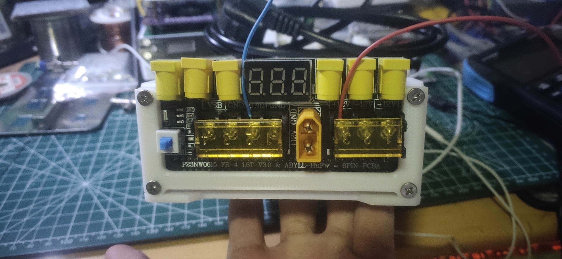
The initial draft is shown below. The Plus version provides 6 DC outputs, and the three bare wire terminals have been retained and brought out from the original VSB network. It also adds indicator lights and a voltmeter function, and the switch has been changed to a 6-pin self-locking switch (I'll just say, "This configuration is luxurious").
I tried to copy it and messed around with it, but it wasn't very aesthetically pleasing. More importantly, it didn't match the power supply cage shell of FrostAutumn. So, after some minor improvements, I got the final draft below. It's undeniably aesthetically pleasing, cough cough... except for the lack of wiring (lol). There's
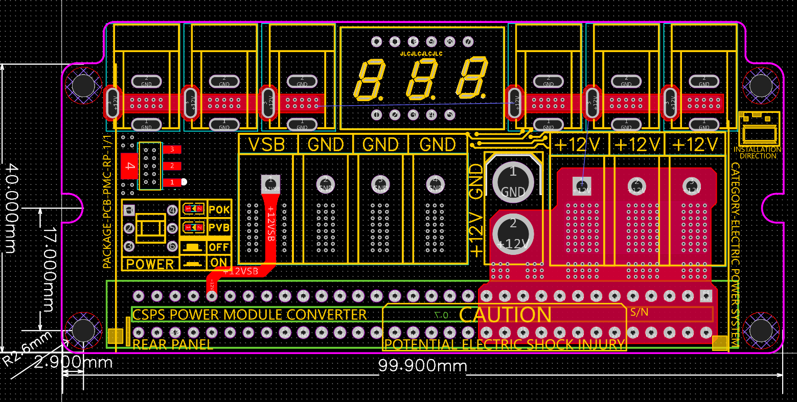
a hidden problem with the wiring here. I hope someone will continue to follow up and share it open source.
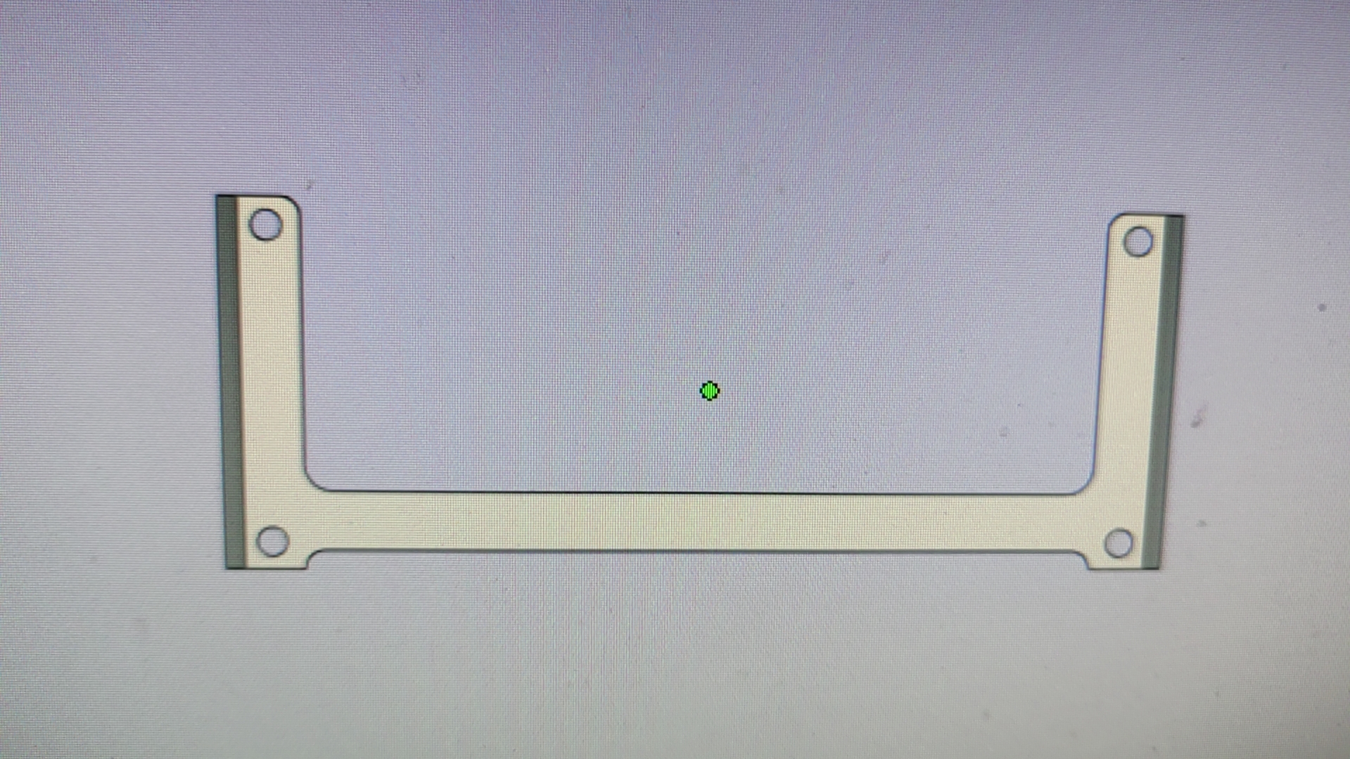
Most importantly, the size is just right (there's only one downside, which is the side panel). The original side panel wasn't suitable for the new power supply board
, so... we redesigned the side panel for the board.

This is the overall effect of the adapter board.
## DC-DC_PD Module:
How can you have a power supply board without a PDDC charging module?
With the idea of browsing Xianyu again (this time I found this fun thing on Taobao),
I looked for small boards/modules that support DC12V input with regulated PD fast charging and 5V, 9V, 12V, and 20V output.
This scenario perfectly matched the requirements of the Taishanpai power supply board, so let's work on it!
**Continue** **"Copying Boards"**

Actually, I did consider using two existing projects on the forum:
① DC-DC step-down module
② FS312 decoy module.
The main reason was: **Inconsistent Interfaces**
Through so much learning and board design, I've replaced the interfaces of most of my small gadgets with Type-C power supply.
And whenever I see something interesting on the forum, I prioritize Type-C when I'm working on it (although most of the open-source projects I work on directly use Type-C interfaces (*^▽^*)).
So, taking this opportunity, I want to unify all the interfaces related to Taishanpai (mainly to adapt to the plus power supply board mentioned above).
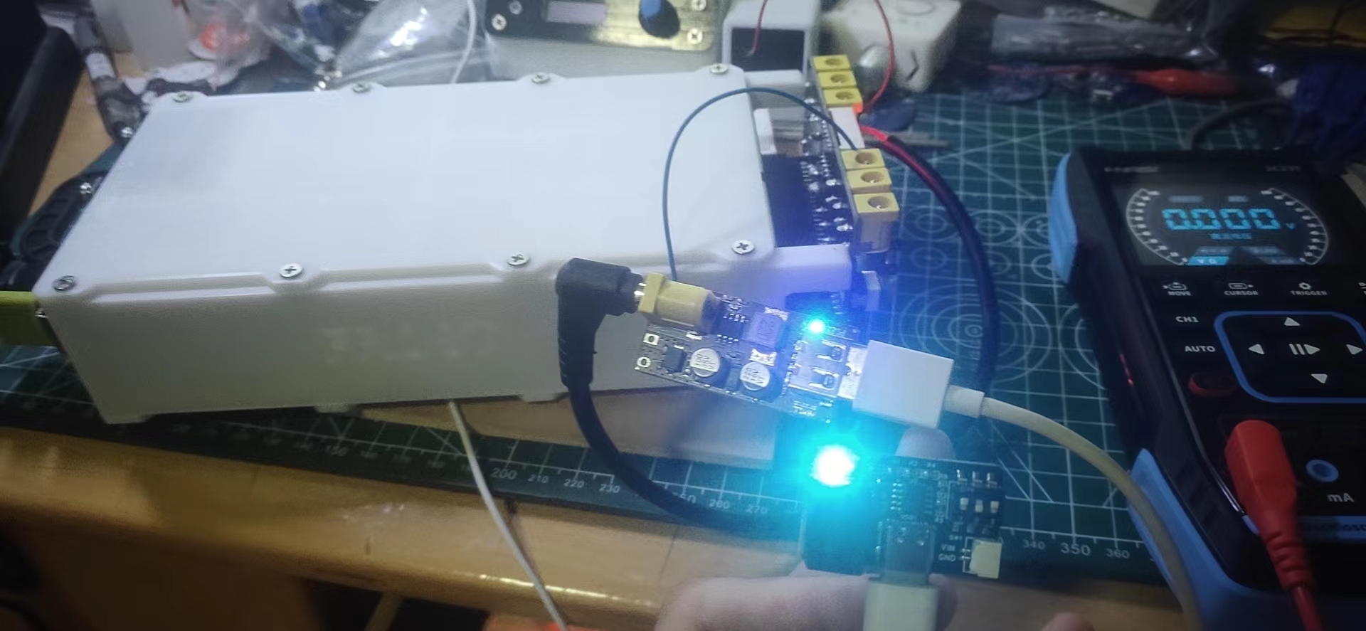
The solution was a success; the 750 standard 12V converter successfully recognized the 5V PD output
. I haven't quite figured out how to convert to PD yet, so I just copied a 12V to standard 5V converter. It's terrible


! Unverified, this is still a potential pitfall; experts are welcome to add more information in the comments section after verification!
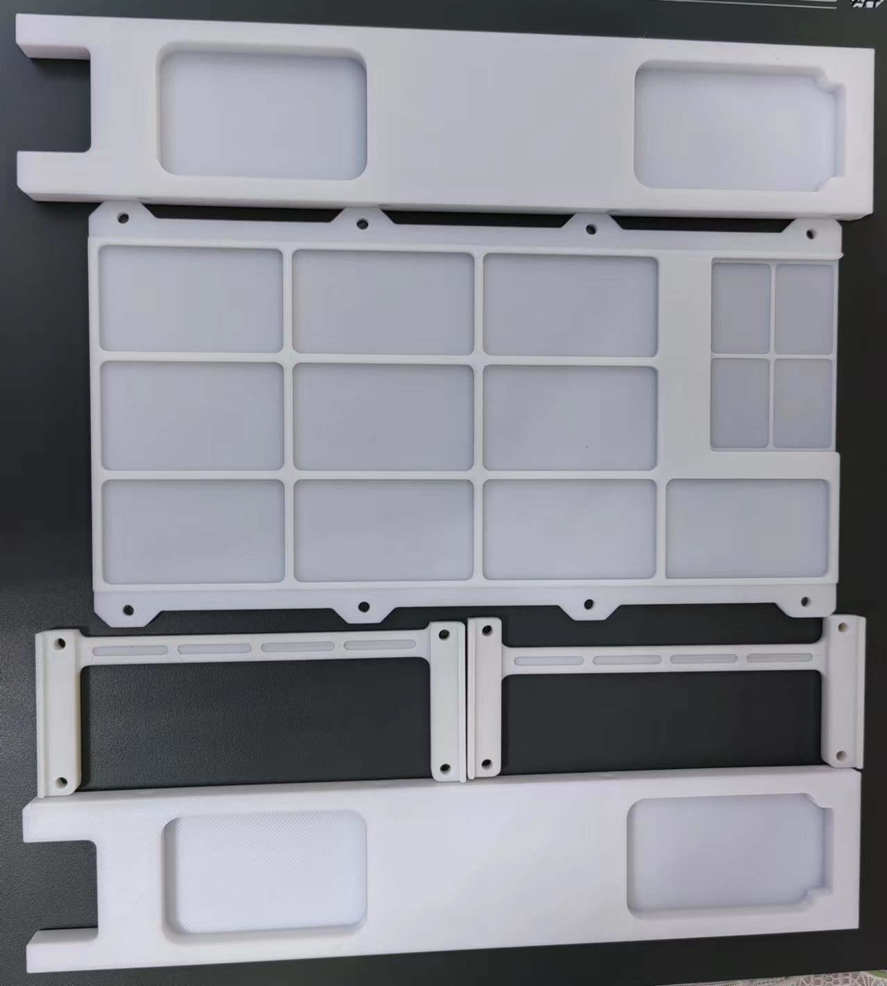
#3DCasing
## While waiting for the screen casing
to be delivered
, since it's a phone, it naturally needs to look like a phone (casing).
While waiting for the delivery, I used LCSC EDA Professional Edition to draw a phone design. (It's more appropriate to call it a tablet) The casing (this is my first time using LCSC EDA professional version to design a casing, and I'm guessing I'll encounter various problems)


is currently being printed:
The overall effect of the casing is as follows:
## Adapter Board Fixing Layer
Having a casing isn't enough, so I also designed an inner fixing layer frame specifically for the adapter board.
Why design a fixing layer? There are several reasons:
1. I need both the MIPI screen interface and touch interface to be under the casing (like a regular mobile phone charging interface).
2. I don't want the adapter board to wobble around inside the casing.
3. The screen bottom shell is metal, and the adapter board PCB is also metal, which can easily cause short circuits.
4. I haven't figured it out yet, I'll add more later (*^▽^*)
Regarding these potential or improveable issues, I've developed a series of optimization plans.
The image below shows my rough plan for internal wiring and fixed board positioning
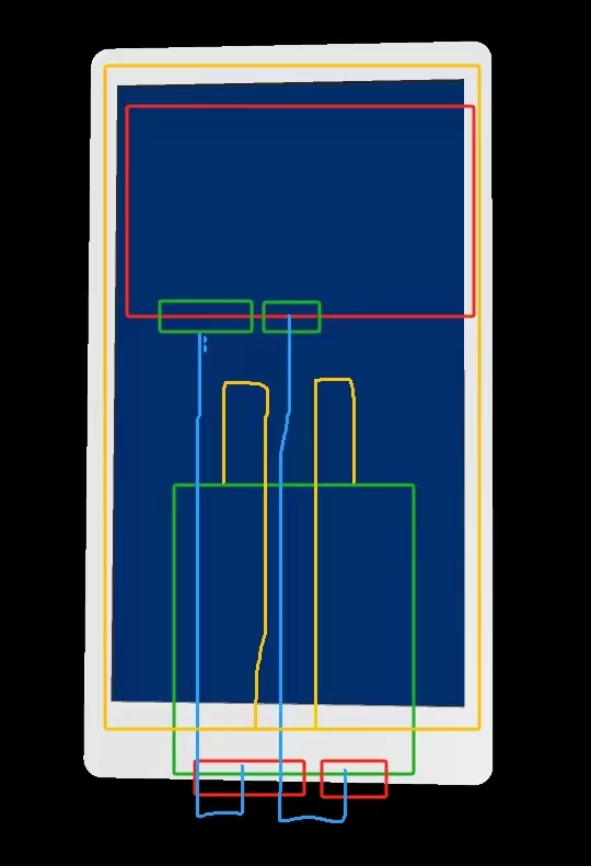
(the board and ribbon cable haven't arrived yet, so I can't verify it).
Waiting for the delivery during the Chinese New Year is indeed a patient process; I got numb from waiting, so I decided to give it a try and make a mezzanine myself (the origin of the problems below). It's because I haven't made many cases, and this was my first time using LCSC professional PCB design to draw a non-shell-like shell, so I had no experience. Please don't criticize me, experts.
I drew my first mezzanine out of boredom (and it failed).
Failure scene (Time: 2:30 AM, February 14, 2024)
: 1. The touch IC wasn't considered, which is unsuitable (a square hole was drilled on the spot)
. 2. The two wires weren't placed symmetrically (the wire holes were made, but they were useless).
3. Because it's a mezzanine, I didn't consider the assembly after closing the cover, so the entire perimeter was made larger.
4. The two holes were too close to the PCB slots, making the fold line uneven (this was a problem discovered later, which I'll explain in detail later).
So... I drew and sketched,

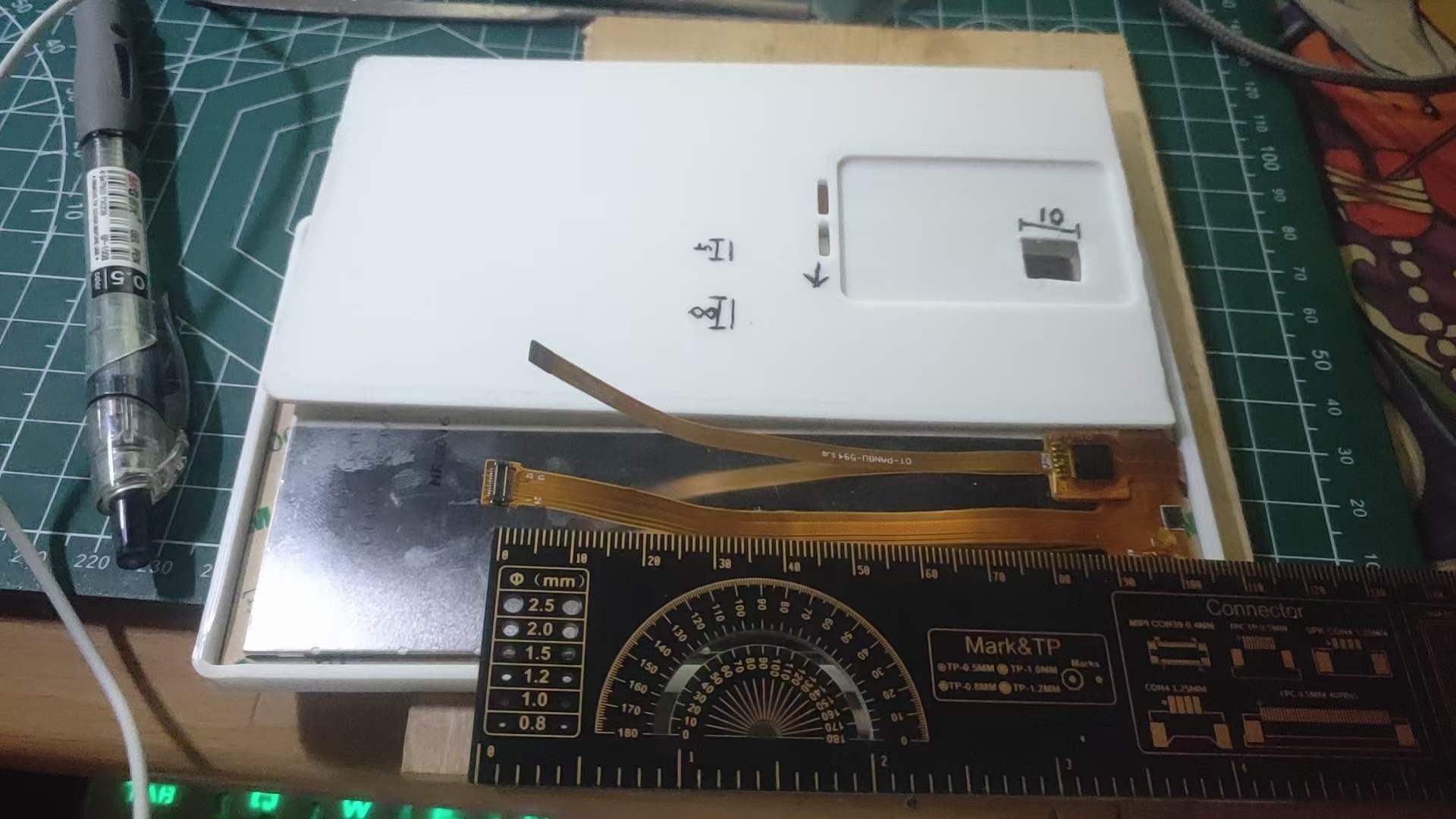
doing all sorts of calculations; finally, I just redrawn a new one. So, I redrawn a new mezzanine board based on the dimensions of the two wires and the existing casing (Time: 4:35 AM, February 14, 2024)
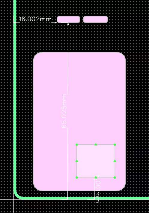
- This time, I considered the fold length of both wires (just consider this rambling).
The total length of the two wires is 112mm
, the interfaces are 8.5mm and 8.8mm,
the board is 10mm from the interface ,
the board length is 50mm, and
the board edge is 5mm (leaving space for the bottom cover inner wall and free space).
Including everything, a single-sided fold of about 65mm shouldn't be unreasonable.
The bottom casing is 4mm high and 2mm thick, with a mezzanine distance of 3mm.
The overall height of the top and bottom casings is 1cm. I estimate that the bottom casing and overall height need to be modified. The assembly height might not be enough.
The PCB thickness is 1mm this time
, but the PCBA thickness will probably reach 1.8-2mm (the interface might be even higher).
*In short:* **The previous outer shell will likely need further modifications after the courier arrives.**
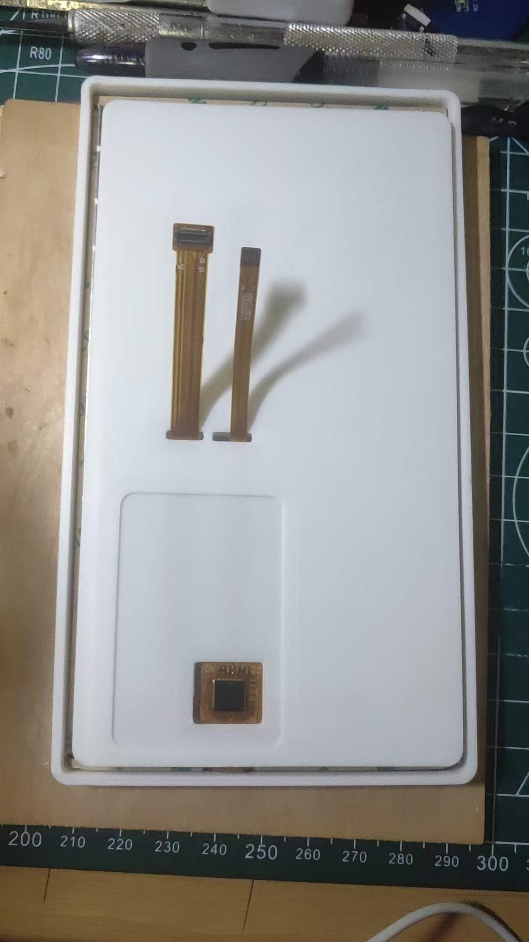
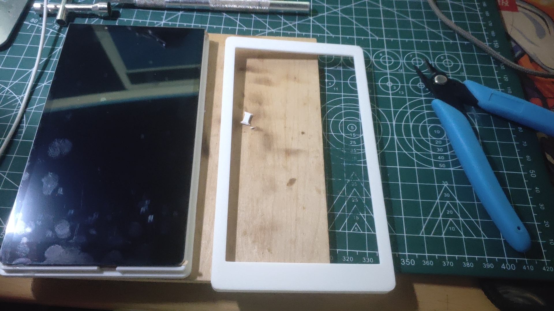
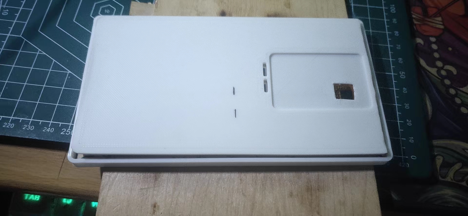
This is the modified inner layer; the effect is quite good after comparison, and it fits perfectly.

The two wires I waited a month for finally arrived today (February 20th)
(the board hasn't arrived yet, so I can't verify it). I've been busy tinkering with DaXian during this time, so I'll leave this project for later (I've already forgotten which project it is).
# DaXian 3.1
Here's a link to a Taishanpai VM virtual machine file (just unzip and import)
: https://pan.baidu.com/s/1EUZPPTkPt8FXSuqMvKTGpw?pwd=tspi Extraction code: tspi
Username: `tspi` Password: `root` (If I remember correctly, this is the one)
While waiting for the delivery, I tinkered with a small screen.
For the specific tinkering process, you can refer to the project of the expert [Taishanpai 3.1-inch screen expansion board](https://oshwhub.com/fengmoxi/tai-shan-pai-3-1-cun-ping-mu-kuo-zhan-ban).
The final result is also awesome.
# Continuing to plant seeds (official expansion boards)
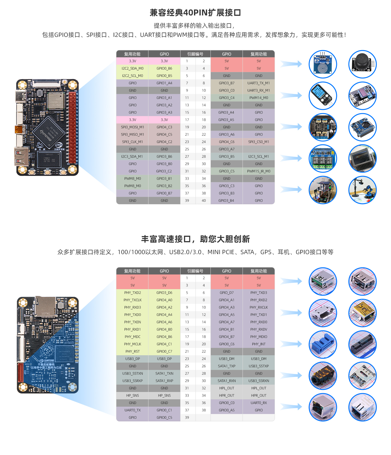
I was bored in the dormitory and made a few official [HUB expansion boards](https://lceda001.feishu.cn/wiki/AYFHwYvMIifaB6k8YwYcsUASnqg).
One batch `0402`, you think about it, you really think about it. **(ಡωಡ)**

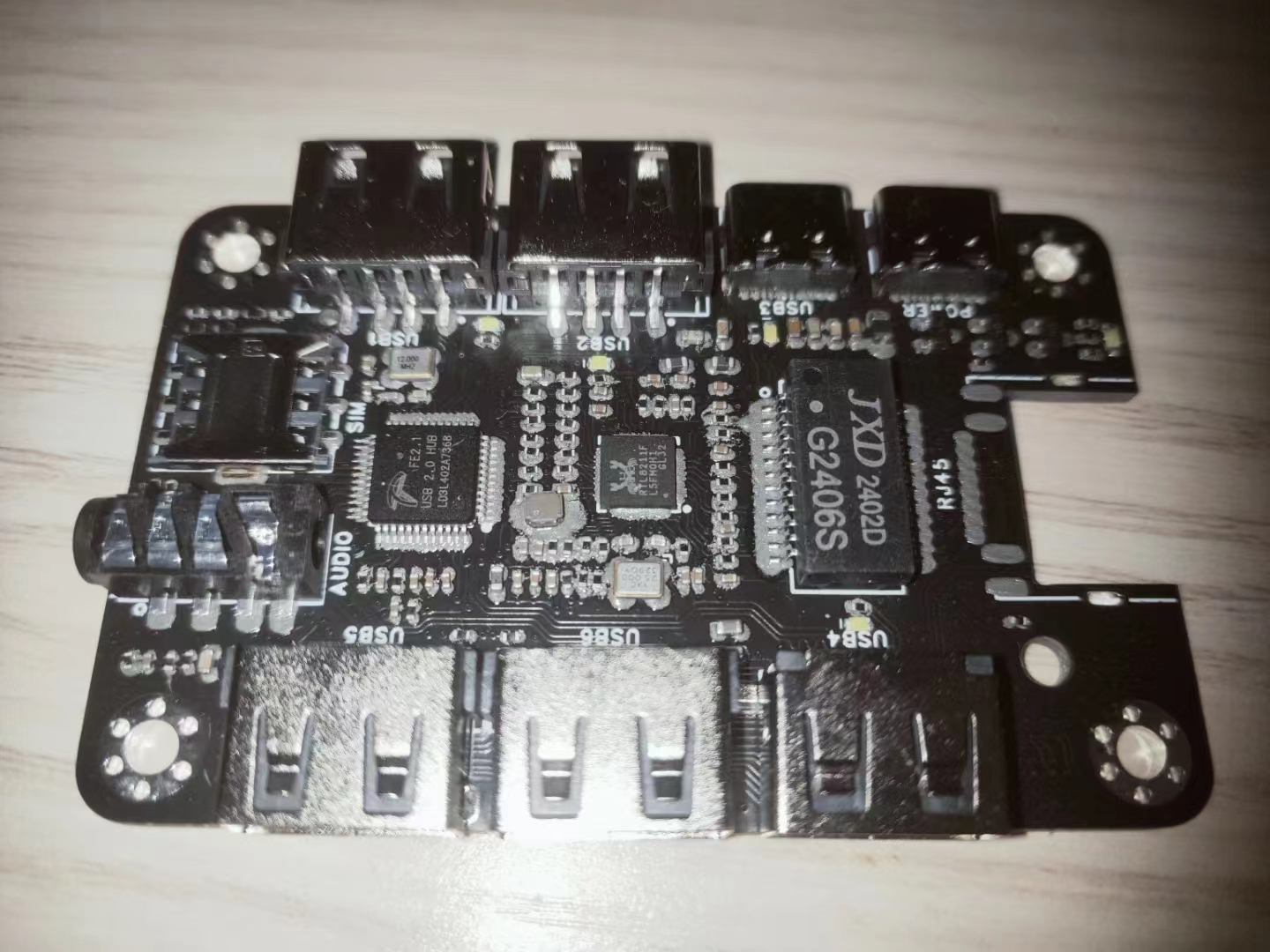
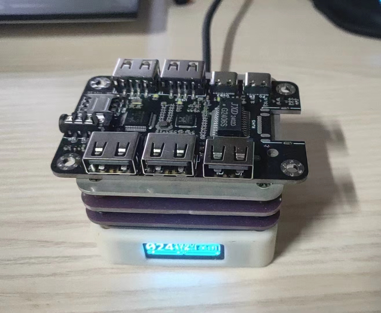
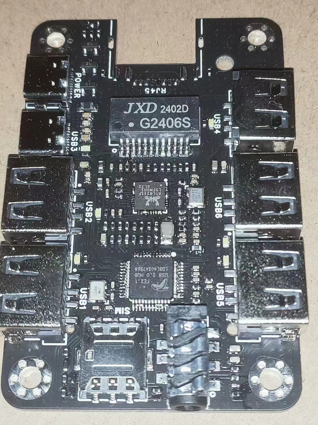
Because I brought the stencil from home to the company, it got crushed on the way and wasn't very flat. The effect after applying it was terrible, and in the end, there were a lot of solder joints, which had to be repaired separately... **o(╥﹏╥)o**
I already have For those interested in using the expansion board, you can refer to this post [【LCSC Taishan Development Board】39Pin Hub 2.0 Ethernet Expansion Board Adaptation Instructions](https://oshwhub.com/article/lichuang-taishan-development-board-39pinhub20-ethernet-expansion-board-adaptation-instructions) for configuration instructions (also by the user `风漠兮`).
# Code Explanation
This article mainly focuses on hardware aspects. For specific Linux learning content, please refer to my newly opened Git repository [Linux_StudyManual](https://github.com/mayjack0312/Linux_StudyManual) (which will be updated periodically).
## Virtual Machine Preparation
Based on official reference materials and existing virtual machine products, there are currently three common choices: `WSL2`, `VirtualBox`, and `VMware`.
Here, I recommend using `VMware 17 Pro`, which is also what I am currently using. The reasons for the recommendation are: it is simple, convenient, and easy to use (errors can be found), and it should also have the fewest errors among these three.
## Ubuntu Image Version Preparation
I tried `22.04.3`, but the compilation failed (`mksquashfs`), wasting a whole day o(╥﹏╥)o.
Finally, I reverted to `18.04.6`, and the compilation was perfectly normal, without any mysterious errors.
## VMware Installation and Usage (These are all posts I've been gathering dust in my CSDN bookmarks)
The following links are in no particular order:
https://blog.csdn.net/Python_0011/article/details/131619864
https://blog.csdn.net/weixin_74195551/article/details/127288338
https://blog.csdn.net/wzk4869/article/details/126775691
https://blog.csdn.net/leah126/article/details/131450225
## Common VMware Ubuntu Installation Issues
- Can't understand English in the software? No problem, I'll teach you how to directly change it to Chinese.
[
Links to various articles on VMware Tools installation and system installation are included
in the
original text
.]不慌
https://blog.csdn.net/Mr_wilson_liu/article/details/117408189
- 如何创建共享虚拟机目录位置(应该用不上,后面会装samba)
https://blog.csdn.net/qq_25427995/article/details/122689786
- 安装并配置ssh远程登录的相关问题
https://blog.csdn.net/weixin_44197719/article/details/119888235
https://blog.csdn.net/chao_shine/article/details/106966854
## 新系统的工具配置(常用的就这几个,其余的大家根据需要自行增加吧)
### vm-tools
属于VMware虚拟机系统装机必备的一个工具了,复制粘贴拖文件...,必不可少的工具
具体安装方法可以看:`VMware_Ubuntu安装常见问题整理` → The content in the link `**Questions about installing VMware Tools**` contains the
following: ### net-tools:
A tool for viewing network information in Ubuntu, essential for system administrators.
Installation command: `sudo apt install net-tools -y`, then enter your system password.
### vim:
One of the built-in editors in Linux, in my opinion... I don't use it at all. This is probably one of the best editors in Linux;
I'll need it to modify configuration files later
. Installation command: `sudo apt install vim -y`, then enter your system password.
### SSH:
An indispensable tool for remote system login, bar none, essential for system administrators.
For specific installation methods, see: `**Common VMware Ubuntu Installation Issues**` → `**Questions about installing and configuring SSH remote login**`.
### Samba
: A new tool I learned from the official documentation. I used to use SSH or FTP instead, but this is much better.
Installation command: `sudo apt install samba smbclient -y`, then enter your system password.
Use the `samba -V` command to check if the installation was successful
. Use `sudo cp`... The configuration file `/etc/samba/smb.conf` is backed up
using the command `/etc/samba/smb.conf.bak`. The `tspi` folder is created
using the command `sudo mkdir -p /home/tspi`. The folder permissions are set to 777
using the command `sudo chmod 777 /home/tspi`. The Samba configuration file is created using the command `sudo vim /etc/samba/smb.conf`.
Its content is:
```conf
[tspi]
path = /home/tspi
browseable = yes
writable = yes
comment = smb tspi_linux_sdk test
```
The `tspi` user is created using the command `sudo smbpasswd -a $tspi`. The user password is entered twice as prompted.
The Samba service is restarted using the command `sudo service smbd restart`.
Virtual machine folder mapping is performed using Windows system network mapping (refer to the documentation).
## SDK Compilation
Refer to the documentation for specific compilation methods (I used a full compilation).
https://lceda001.feishu.cn/wiki/Da5owUV4dipiqUkZycbcxckinvc
**Note: When selecting the power supply at the end of the compilation, choose 1 for 4 and 6, and 2 for the rest.**
**Recommendation:** Download and extract the `dl` package of `buildroot` before compiling. This can greatly shorten the compilation time.
- i9-10900k, virtual machine with about 24GB, actual testing shows that compiling Linux only takes half an hour
. ### Common Errors
Compiling `Python` resulted in the error:
```
/usr/bin/env: python: No such file or directory
```
Solution:
```
apt-get install python3 -y
whereis python3
sudo ln -s /usr/bin/python3 /usr/bin/python
```
Or try:
```
sudo apt install python-is-python3
```
### Screen porting
is similar to the adapter board, using a readily available 6-inch screen porting solution (the universal copy method).
Related materials have been open-sourced by a developer, see [Gitee](https://gitee.com/fengmoxi/tspi-stl6_0_1_2_a)
#### Patch file usage
```
// Download the patch file to the same directory as the SDK
wget https://gitee.com/fengmoxi/tspi-stl6_0_1_2_a/raw/master/linux-kernel-STL6_0_1_2_A.patch
// Linux SDK
patch -p1 -N -d tspi
```
- If you encounter a problem like `Hunk #1 FAILED at xxx(different line endings).`, please use `dos2unix` to convert the format of the corresponding file.
```
sudo apt install dos2unix
dos2unix tspi_linux_sdk/kernel/arch/arm64/boot/dts/rockchip/tspi-rk3566-dsi-v10.dtsi
```
#### Brief Description of Touch Driver
1. Set the content of the `gtp_dat_9_7` array in `/kernel/drivers/input/touchscreen/gt9xx/gt9xx_cfg.h` to
```
#include "GT970_Config_20240119_160927.cfg"
```
2. Copy `GT970_Config_20240119_160927.cfg` to `/kernel/drivers/input/touchscreen/gt9xx`.


 京公网安备 11010802033920号

 LT1336IS


