The following is a description of the finished product
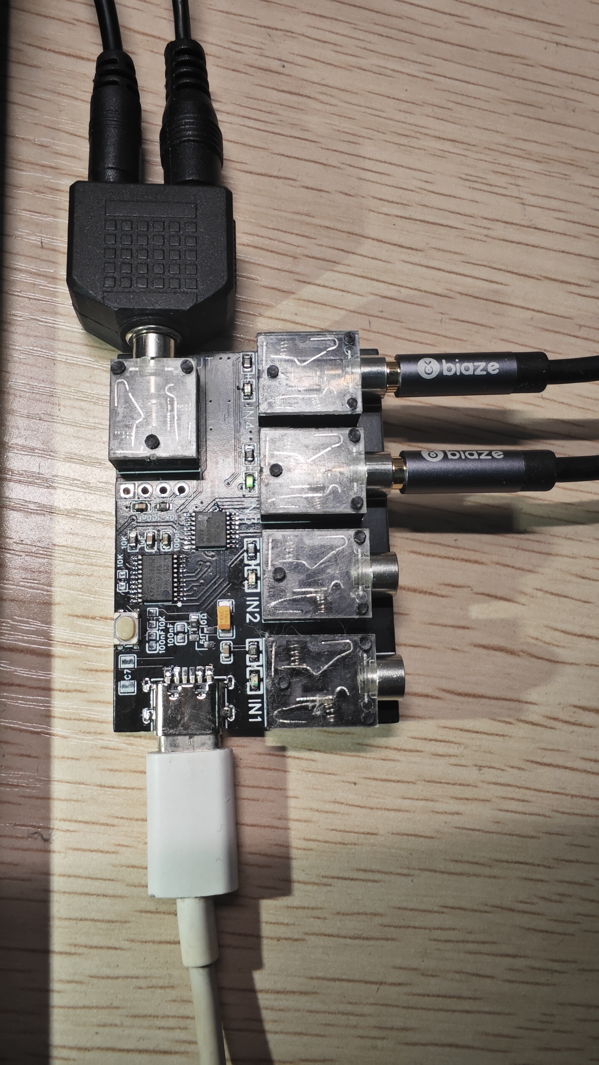
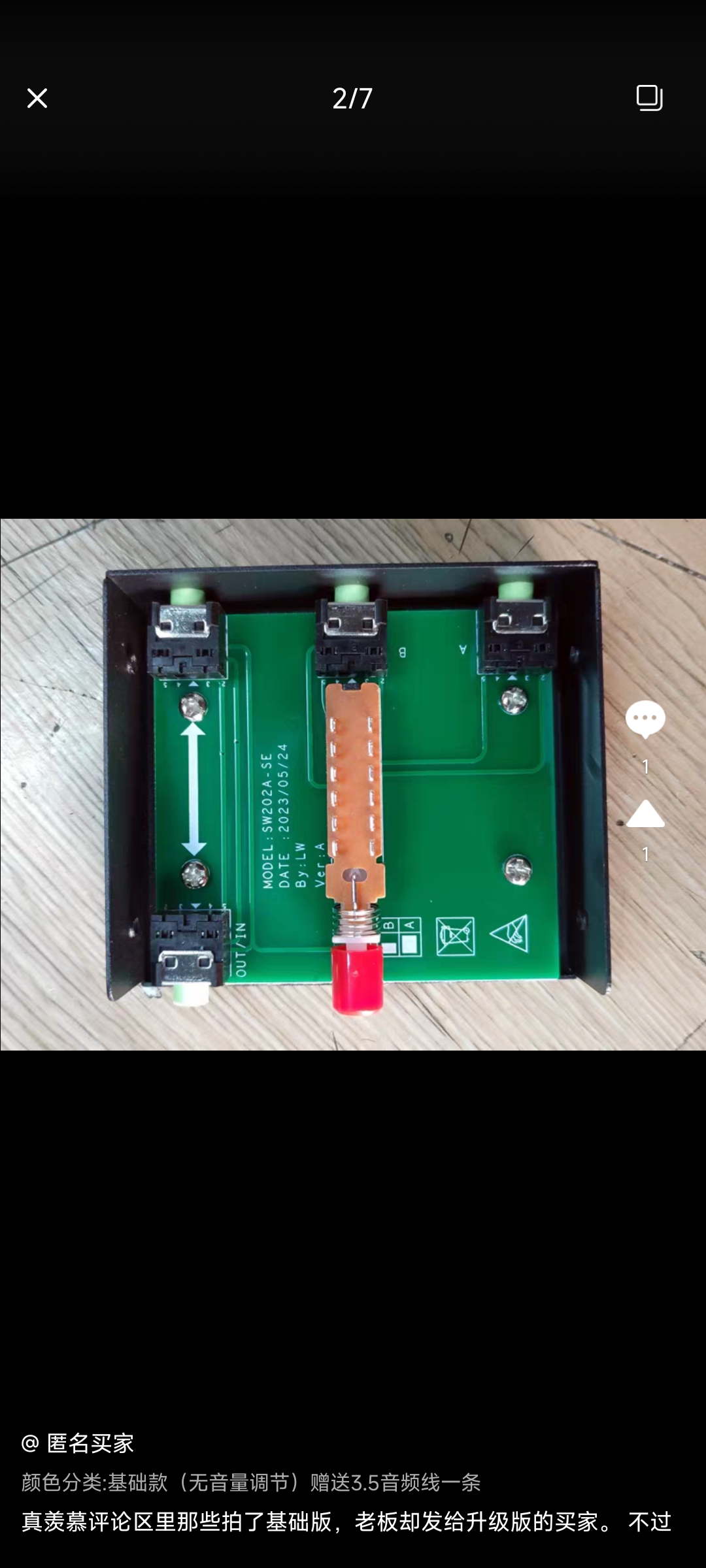
: An audio switcher is available on Taobao. Looking at the teardown photos in the comments, it's just a metal casing, a PCB, and a mechanical switch for multiplexing, selling for around 30 RMB. Moreover, these mechanical switches seem likely to develop poor contact and produce noise within a few days.
Therefore, I DIYed one using an analog switch chip. The schematic and code are very simple. This DIY project only implements switching; the impact on signal transmission is not considered. Testing showed no significant impact on speakers costing
around 100 RMB. (Taobao listings are listed below.)
Audio switching code (four inputs, one output).rar
PDF_4 Inputs 1 Output 3.5mm Audio Switch.zip
Altium_4 Inputs 1 Output 3.5mm Audio Switch.zip
PADS_4 Inputs 1 Output 3.5mm Audio Switch.zip
BOM_4 Inputs 1 Output 3.5mm Audio Switch.xlsx
94696
#Training Camp# A small mobile phone based on the Taishan School
Smartphones based on the Taishanpai development board
The circuit part
was completed in 3 hours, but a considerable amount of time was spent on the differential pairs.
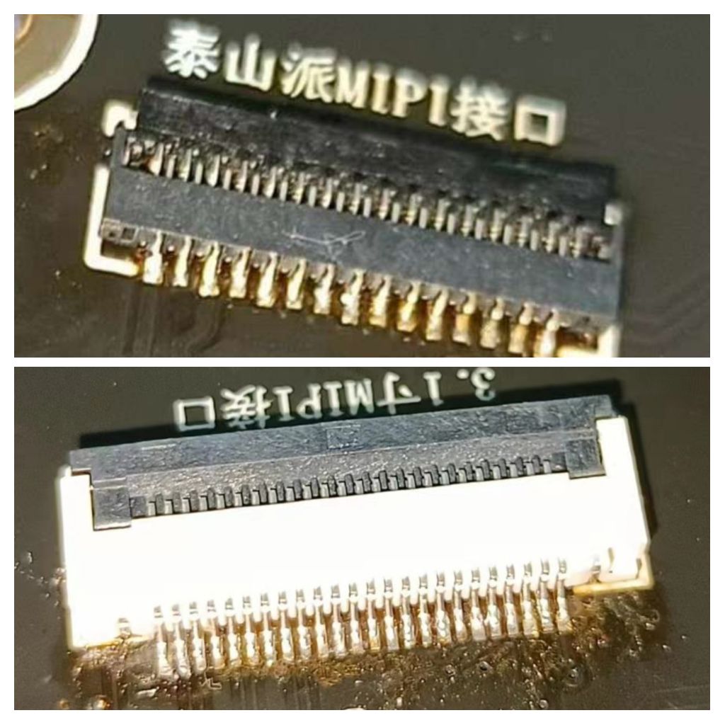
Planned additions: Soldering the 31P FPC socket for
the battery
and camera hardware
was quite difficult. After several attempts, I switched to a hot plate and succeeded on the first try (there was a slight solder bridge after the hot plate, which was finally resolved by referring to a Bilibili tutorial). FPC socket close-up: Driver part . Planned functions: Backlight , touch, boot logo, screen rotation, automatic brightness, application startup. Problems encountered: VMware virtual machine can install tools: `sudo apt-get install open-vm-tools-desktop` `suto apt-get install open-vm-tools` ` sudo reboot` //Reboot . When compiling, use the snapshot function flexibly to prevent some strange events. During full Android system compilation, the error `/bin/sh: 1: lz4c: not found` occurred: Execute `apt-get install liblz4-tool`. If the screen does not light up after assembly and power-on, you can use the screen mirroring tool provided in the official documentation to test if there is a problem with the Taishanpai (a component). To be updated... Reference Links : LCSC Taishanpai Training Camp Learning Notes -- Linux SDK Compilation Environment Setup and Verification (Part 1); LCSC Development Board TSPI-RK3566 Learning Notes; Feng Moxi/TSPI-D310T9362V1 Taishanpai Development Environment Installation and SDK Compilation; [Android] System SDK Compilation of Android 11 SDK; [Fat Girl Mobile Phone] Taishanpai RK3566 Development Board
Real shot.jpg
Demo video.mp4
PDF_#Training Camp# Based on the Taishan School's Small Mobile Phone.zip
Altium_#Training Camp# A small mobile phone based on the Taishan School.zip
PADS_#Training Camp# Based on the Taishan School's small mobile phone.zip
BOM_#Training Camp# A small mobile phone based on the Taishan School.xlsx
94697
GD32E230C8T6 Expansion Board - Remote Control
Create a remote control expansion board based on the GD32E230C8T6 expansion board.
Based on the GD32E230C8T6 expansion board, this project creates a remote control expansion board with the following components:
1. A 1.8-inch TFT display screen
; 2. Two joysticks
; 3. Three point sensors;
4. Several buttons;
5. One NRF21L01 transmitter for transmitting signals.
The buttons, knobs, and screen have been verified; the code is attached.
1716012916128.jpg
1716012916146.jpg
04KEY-Template-B.zip
mmexport1716019174865.mp4
PDF_GD32E230C8T6 Expansion Board - Remote Control.zip
Altium_GD32E230C8T6 Expansion Board - Remote Control.zip
PADS_GD32E230C8T6 Expansion Board - Remote Control.zip
BOM_GD32E230C8T6 Expansion Board - Remote Control.xlsx
94699
Power bank/portable charger (dual solution TP5400/IP5358_BZ) has been verified.
[1] The solution uses the No. 2 power supply 18650 battery as the power supply. The power management IC is TP5400, which is very easy for beginners to use (I was one too).
[2] The solution uses Ingenic IP5358_BZ as the main control chip. It has a large capacity and multiple speed options and supports mainstream fast charging protocols.
[1] Option 1: A simple power bank based on TP5400 uses 18650 lithium batteries and can power 1-2 18650 lithium batteries.
When soldering, a soldering station or hot air gun should be used. Prioritize soldering the components to be soldered (TP5400).
For surface-mount aluminum electrolytic capacitors and LEDs containing plastic parts, it is not recommended for beginners to use a hot air gun or soldering station (it is easy to melt or damage the components).
Battery terminals are provided (usually). No battery box is needed. The battery can be fixed by applying glue or tape.
Output +5V (verified).
TP5400 processing requires a hot air gun or soldering station!
[2] Option 2: Uses Ingenic IP5358_BZ as the main control chip, supporting mainstream charging protocols on the market: PD, QC, VOOC (Apple's LIGHTING interface can be used as a power bank charging interface, but an Apple handshake communication chip needs to be purchased separately, so it is not designed. You can modify it yourself. See the datasheet for details).
USB-A*2 output | The USB-C*1 input/output
chip datasheet can be found here.
This first version of the circuit is a typical circuit from the datasheet (solution verification board). The bolded lines in the datasheet have been thickened and tinned to increase current carrying capacity, and the size is kept as small as possible (this may be continuously verified and improved).
To ensure functionality, it is recommended to purchase the IP5358_BZ from the LCSC online store
. Soldering requires a hot air gun or soldering station, and the soldering is relatively difficult. Carefully check for cold solder joints or missing solder joints, as it is difficult to modify surrounding components after soldering! When soldering, first solder the front IC, resistors, capacitors, and USB-C female connector. Note! Please use solder paste (preferably lead-free solder, which can be supplemented with flux for easier positioning) when soldering the USB-C female connector and IP5358_BZ. However, lead-free solder will result in a very strong bond, so it's best to do it in one go. After that, solder the surface-mount resistors and capacitors on the back, and finally solder the through-hole components. (The main control chip and Type-C female connector are made of plastic; do not solder at high temperatures for extended periods as they will melt!!!)
Note: For solid-state capacitors (C17), use slotted designs and place the pads connected to the copper pour for 3D soldering. Adjust the leads of the surface-mount solid-state capacitors by gently prying them open!
11.8 Update Optimization Log:
1. During the soldering process, it was found that the battery NTC thermistor pad (0805) was too small, making it inconvenient to solder and lead out. It is recommended to modify it yourself (modified).
2. The size of the slot of C17 (solid capacitor) has been reduced (modified).
3. Too many meaningless GND network vias have been reduced. During soldering, it was found that even with JLCPCB's default via cover solder mask, solder paste still easily fills into the via grooves, affecting the board's appearance (mainly color silkscreen printing) and increasing losses and risks (modified).
//
11.19 Update Optimization Log:
1. The positions of the filter capacitors of all USB interfaces have been adjusted. The previous positions were too close to the interfaces, which was unreasonable. Although the actual impact is not significant, it has reduced some potential problems (modified)
. 2. The position of the wiring window has been optimized (modified). 3. The position of the battery line pad has been adjusted and optimized (not modified yet).
11.20 Update Log: I watched and learned about the layout and design ideas of power bank products. I have the idea of redrawing the PCB board and improving and upgrading it to create a new project.
11.20 Project Release
2024.1.22 Update Log:
1. Adjusted and optimized the position of the battery negative electrode pad (modified).
2. Actual soldering summary: JLCPCB's color silkscreen board, when QFN packaged or with pads too close together, will have solder resist layer reliability issues, easily breaking and falling off like wall plaster. This may be due to the white underlayer causing "brittle solder resist (silkscreen)" after silkscreening. The silkscreen damage rate around the pads is very obvious on the heating table; it is not recommended to use color silkscreen for this project.
2024.5.18
Meow: Uploaded pictures.

Power bank charging test.mp4.mp4
f264ba216432030e64b4dd1635ecf532.mp4
PDF_Power Bank (Dual Solution TP5400-IP5358_BZ) Verified.zip
Altium Power Bank (Dual Solution TP5400 IP5358 BZ) Verified.zip
PADS Power Bank (Dual Solution TP5400 IP5358 BZ) Verified.zip
BOM_Portable Power Bank_Power Bank (Dual Solution TP5400_IP5358_BZ) Verified.xlsx
94700
electronic


 京公网安备 11010802033920号

 T493D227J006CT6410


