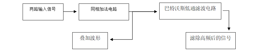
 该电路包含两个组成部分,分别是运放搭建的加法电路和巴特沃斯低通电路。信号发生器提供两路信号,加法电路对两路信号求和A路:幅值2V,频率150Hz的正弦波,B路:幅值1V,频率5KHz的正弦波,实现两路信号的叠加。巴特沃斯低通滤波电路对前路的叠加信号进行滤波,滤除高频成分,得到A路的输入信号。
 2. Resistors: Common 10KΩ 0603 package surface mount resistors are selected, which are small and inexpensive. (Here, I prioritize a compact and refined board design. Beginners may find soldering 0603 package surface mount resistors difficult; consider your soldering ability and choose 0805 package or through-hole resistors.)
 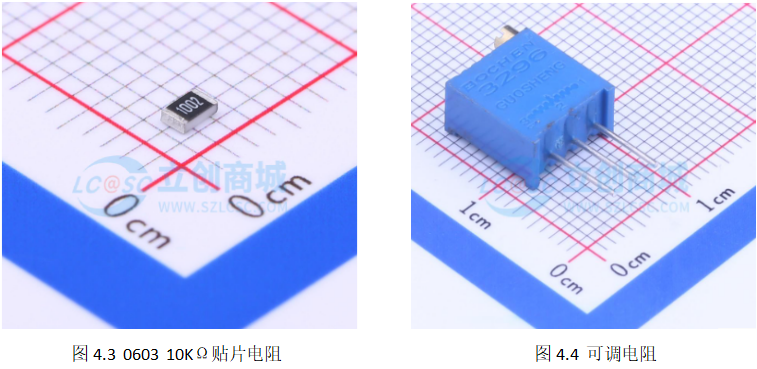 4. Capacitors: To filter out the 5kHz high-frequency sine wave, theoretically the larger the capacitance, the better. However, considering factors such as actual size and price, we chose common 100nF 0603 package surface-mount capacitors, which are small and inexpensive.
 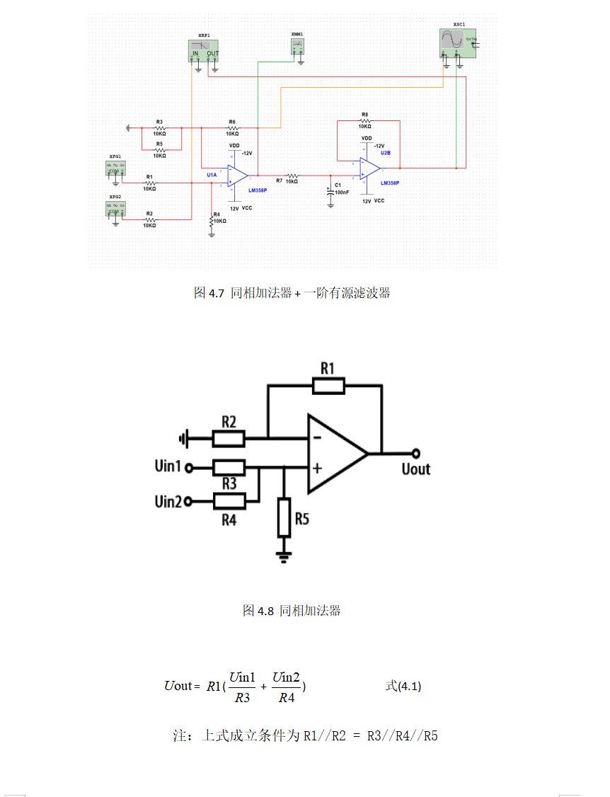 4.3 Simulation and Result Analysis
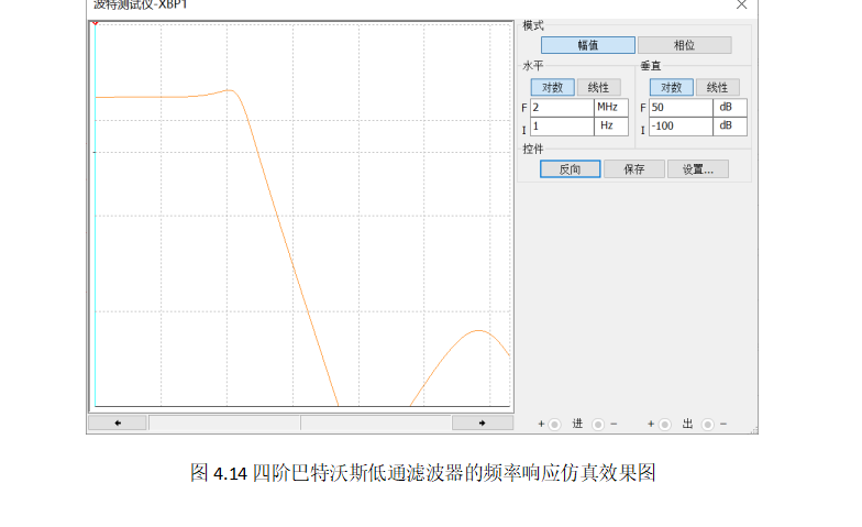 We can see that the effect achieved by the simple first-order low-pass filter circuit is significantly distorted. Therefore, we introduce a Butterworth low-pass filter circuit here. Under similar cutoff frequencies, it can be clearly observed that the transition region of the Butterworth low-pass filter is steeper than that of the first-order low-pass filter. While a fourth-order Butterworth low-pass filter offers a flatter passband in practical applications, its frequency drop-off rate slows down with increasing order. This not only increases design complexity but also makes it prone to a bulge in the passband due to the quality factor Q if the parameters are not properly tuned. Furthermore, since the LM358 only integrates two op-amps, using a fourth-order Butterworth filter increases material consumption and may be more cumbersome to tune, potentially resulting in performance inferior to a second-order Butterworth low-pass filter. Therefore, a second-order Butterworth filter was ultimately chosen for the prototype.
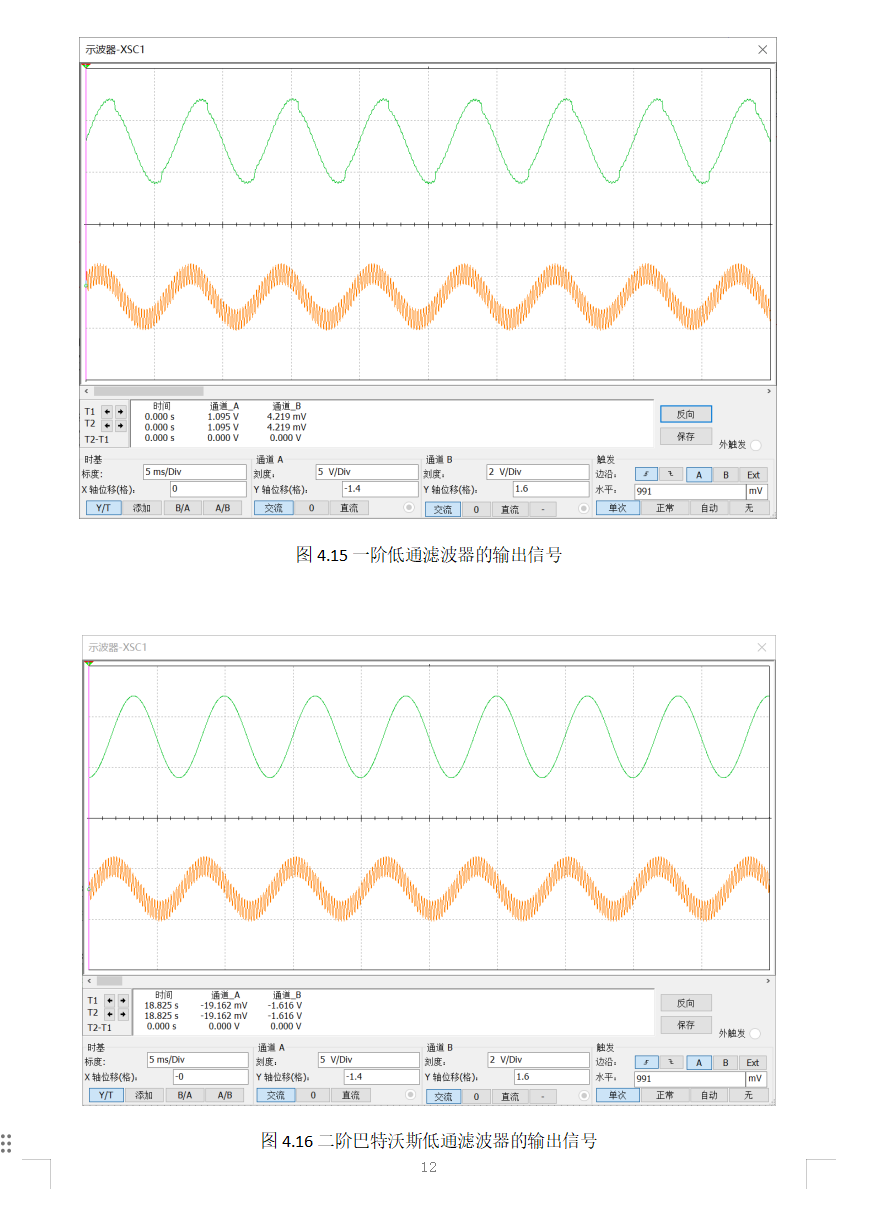

 Under the same measurement dimensions, significant distortion was clearly observed in the output waveform of the first-order low-pass filter, even with the cutoff frequency set close to 150Hz. It's easy to predict that under real-world interference, the waveform distortion would be even greater, which is unacceptable. In contrast, the improved Butterworth low-pass filter solution produced a completely distortion-free output waveform, ensuring the filtering quality of the prototype. The fourth-order and second-order Butterworth low-pass filters produce almost identical signal outputs in simulations, making the second-order filter the optimal choice due to its ease of debugging and material savings.
  During the layout process, copper plating was used for both 12V power supplies to provide sufficient current carrying capacity. The signal section and power section were laid out separately to avoid interference and were grounded. Because the circuit connection here is very simple, the global routing was kept as free of vias as possible to ensure smooth wiring and avoid right-angle traces that could cause signal reflection and interference. Finally, some restricted areas were placed during copper plating to remove sharp copper areas and dead copper (islands) to avoid antenna effects. (Actually, the circuit here is very simple. For convenience, breadboards or perforated boards can also be used to build the circuit. However, it may not be as stable. If a short circuit is encountered during the defense, it will burn out... Anyway, building a board is free [doge dog head for protection]).
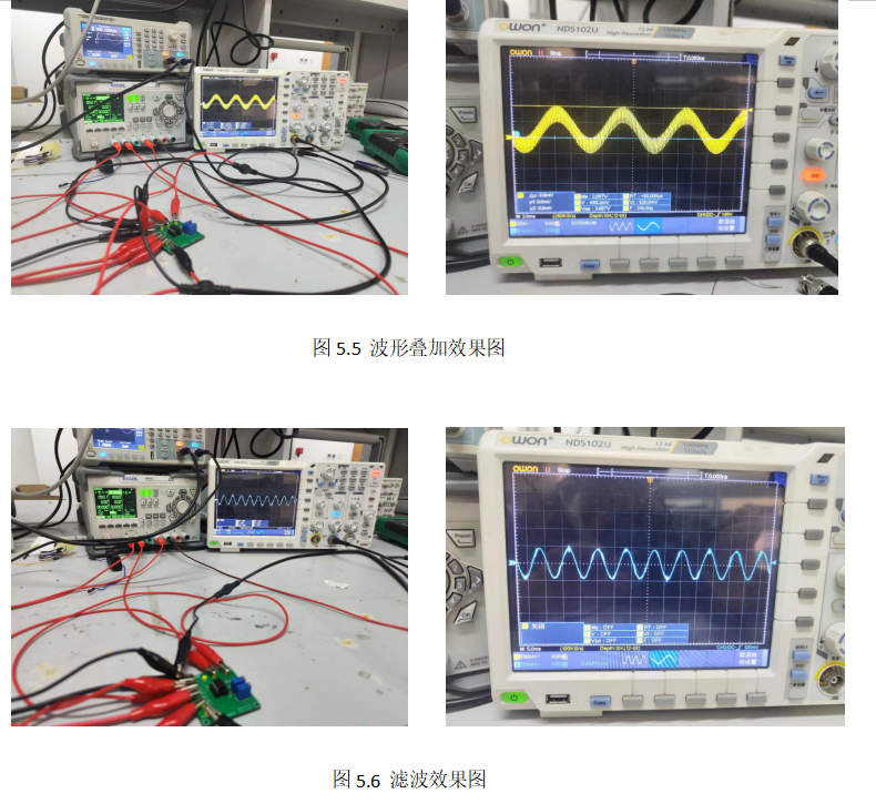

All reference designs on this site are sourced from major semiconductor manufacturers or collected online for learning and research. The copyright belongs to the semiconductor manufacturer or the original author. If you believe that the reference design of this site infringes upon your relevant rights and interests, please send us a rights notice. As a neutral platform service provider, we will take measures to delete the relevant content in accordance with relevant laws after receiving the relevant notice from the rights holder. Please send relevant notifications to email: bbs_service@eeworld.com.cn.
It is your responsibility to test the circuit yourself and determine its suitability for you. EEWorld will not be liable for direct, indirect, special, incidental, consequential or punitive damages arising from any cause or anything connected to any reference design used.
Supported by EEWorld Datasheet
EEWorld
subscription
account

EEWorld
service
account

Automotive
development
community

Robot
development
community

About Us Customer Service Contact Information Datasheet Sitemap LatestNews


Room 1530, 15th Floor, Building B,
No.18 Zhongguancun Street,
Haidian District,
Beijing, Postal Code: 100190
China
Telephone: 008610 8235 0740
 京公网安备 11010802033920号

 IS61LV25616-8B


