 and Schematic Diagram:
 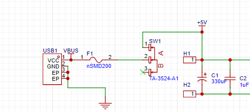 USB1 uses TYPE-C pin 4 as the power input for the entire board. A 6V/2A fuse is used for circuit break protection. A switch is used to easily turn the fan on and off. H1 and H2 are the two test points at the input terminals.
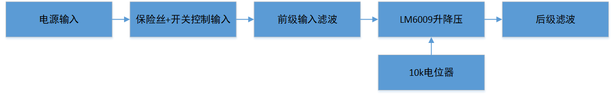
  The pre-amplifier uses a combination of one large and one small capacitor for filtering, and an M4 reverse protection diode. Connecting pin 2 to H5 controls the power-on; the default is a floating high-level input. Pin 5 uses an external resistor divider network; FB detects and adjusts the output voltage. The feedback threshold voltage is 1.25V. The output stage uses another combination of one small and one large capacitor for filtering. An inductor + capacitor combination is used to achieve low ripple output.
 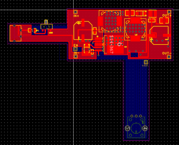 This circuit uses a type C input, and switches for control and short-circuit protection. This pistol-like design is convenient to combine with a JLCPCB box, a Delta fan, and an external voltage and current meter. This circuit uses a large area filling method to replace the wiring, especially the delta output of LM6009, which is filled with a large area and has vias for heat dissipation, so that it does not get hot while handling large current.
  noted
noted 
All reference designs on this site are sourced from major semiconductor manufacturers or collected online for learning and research. The copyright belongs to the semiconductor manufacturer or the original author. If you believe that the reference design of this site infringes upon your relevant rights and interests, please send us a rights notice. As a neutral platform service provider, we will take measures to delete the relevant content in accordance with relevant laws after receiving the relevant notice from the rights holder. Please send relevant notifications to email: bbs_service@eeworld.com.cn.
It is your responsibility to test the circuit yourself and determine its suitability for you. EEWorld will not be liable for direct, indirect, special, incidental, consequential or punitive damages arising from any cause or anything connected to any reference design used.
Supported by EEWorld Datasheet
EEWorld
subscription
account

EEWorld
service
account

Automotive
development
community

Robot
development
community

About Us Customer Service Contact Information Datasheet Sitemap LatestNews


Room 1530, 15th Floor, Building B,
No.18 Zhongguancun Street,
Haidian District,
Beijing, Postal Code: 100190
China
Telephone: 008610 8235 0740
 京公网安备 11010802033920号

 STK12C68-5L45I


