1WOAmwkS22

Compass Clock 2.0

 
Overview
The open-source ESP32-S3 compass clock casing is
an upgraded version of the previous generation, using 3D printing and resin casting. It features optimized functional logic and
a better casing design. Installation video included.
The software is available at the open-source address below.
 
The casing files are below, and the dial features purchased gilded crystal lettering.
CAD drawing.rar
3D model.rar
Cover (1) - Model.pdf
PDF_Compass Clock 2.0.zip
Altium_Compass Clock 2.0.zip
PADS_Compass Clock 2.0.zip
BOM_Compass Clock 2.0.xlsx
95160
STM32F407VET6 Core Board Design
The STM32F407VET6 core board design is mainly a summary of the core board PCB design. It is developed based on STM32F407VET6 and is intended for developers to refer to and learn from. My own level is limited, so please point out any shortcomings.
The STM32F407VET6 core design, with detailed circuit descriptions, can be found on CSDN. The LCSC platform primarily provides open-source schematics and PCB layouts for developers to reference and learn from. PCB routing and serpentine routing require special attention.
CSDN detailed introduction link: https://blog.csdn.net/weixin_52531699/article/details/137430301?spm=1001.2014.3001.5501
Baidu Cloud chip manual and test code link: Extraction code: 0h3n > https://pan.baidu.com/s/1Os8tppub4f810_kKUejz5Q?pwd=0h3n Extraction code: 0h3n 
 
PDF_STM32F407VET6 Core Board Design.zip
Altium_STM32F407VET6 core board design.zip
PADS_STM32F407VET6 Core Board Design.zip
BOM_STM32F407VET6 Core Board Design.xlsx
95161
STC32-based minimum system board
1. Implement flowing light effects based on the STM32F103RCT6 main control chip.
2. Implement ADC detection function
. 3. Adopt a key-operated operation process
. 4. Implement PWM output.
I. Component Features
1. Using the TS431L chip: Adjustable output voltage up to 36V; Low dynamic output impedance, typically 0.2Ω; Current capture capability from 1 to 100mA; Equivalent temperature coefficient over the entire temperature range, typically 50 ppm/s; Effective temperature compensation over the entire operating temperature range; Low output noise; Fast voltage turn-on response.
 
2. Using the TPS54331 buck chip: Integrated 80mΩ high-side MOSFET; Supports up to 3A continuous output current; Cycle-by-cycle current limiting, frequency foldback, and thermal shutdown protection. The TPS62933 is used to implement a 30V input voltage converter with higher frequency, lower IQ, and improved EMI.
 
Summary:
 Through the development of this project, I have gained a deeper understanding and familiarity with STM32 microcontroller development and applications.
PDF_STC32-based Minimal System Board.zip
Altium_STC32-based Minimal System Board.zip
PADS_STC32-based Minimal System Board.zip
BOM_STC32-based Minimum System Board.xlsx
95162
SafetyNodes
Safety loop node of Beijing Institute of Technology pure electric formula team
The core principle of Formula One racing is the pursuit of ultimate speed. Therefore, high motor speeds and high battery voltages mean a high risk factor. To ensure the safety of the car and driver, a safety circuit is essential. Only when this circuit is open can the car be powered on and run normally; hence the name "safety circuit." This circuit is actually composed of multiple safety switches connected in series. Each switch corresponds to a specific component on the car. When the component is functioning normally, the switch is closed. When all components are functioning normally, the safety circuit is open, indicating that the car can receive high voltage. During operation, if any component malfunctions, the safety circuit disconnects, automatically reducing the high voltage, thus protecting the car and driver.
PDF_SafetyNodes.zip
Altium_SafetyNodes.zip
PADS_SafetyNodes.zip
BOM_SafetyNodes.xlsx
95163
RP2040 core board (M.2 2230)
RP2040 core board, M.2 2230 form factor
The PR2040
core board

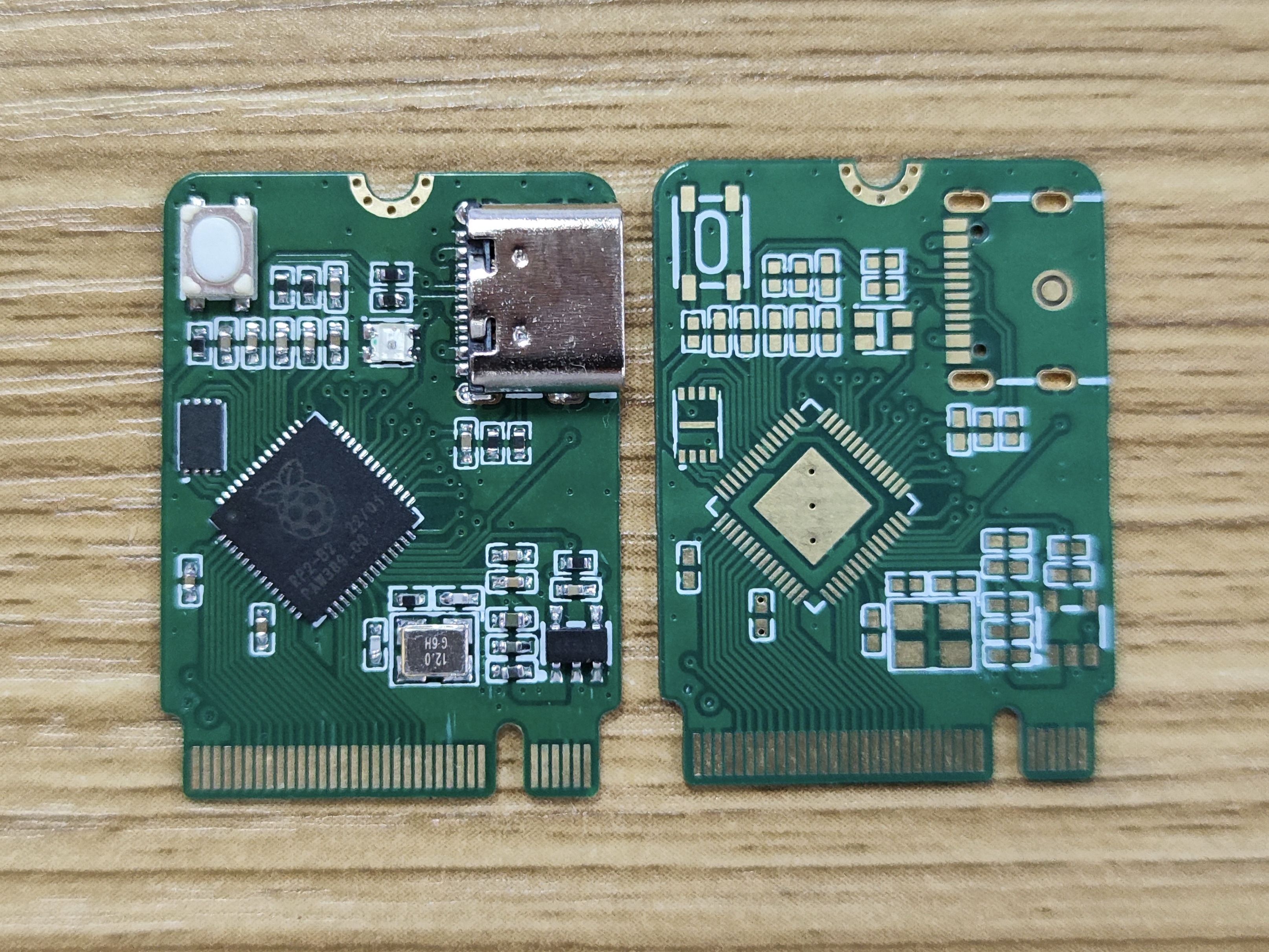
uses an M.2 B-KEY interface and a 2230 package, with an area only slightly larger than the PR2040 Zero by a few millimeters.
The original LEDs have been replaced with WS2812 RGB LEDs.
A reset button has been added (the preview image is from the first version, so it's not present).
All I/O ports are brought out.
Prototyping uses a four-layer board, 0.8mm thickness, and immersion gold plating.

[Image Preview]
PDF_RP2040 Core Board (M.2 2230).zip
Altium_RP2040 core board (M.2 2230).zip
PADS_RP2040 Core Board (M.2 2230).zip
BOM_RP2040 Core Board (M.2 2230).xlsx
95164
Laptop charger
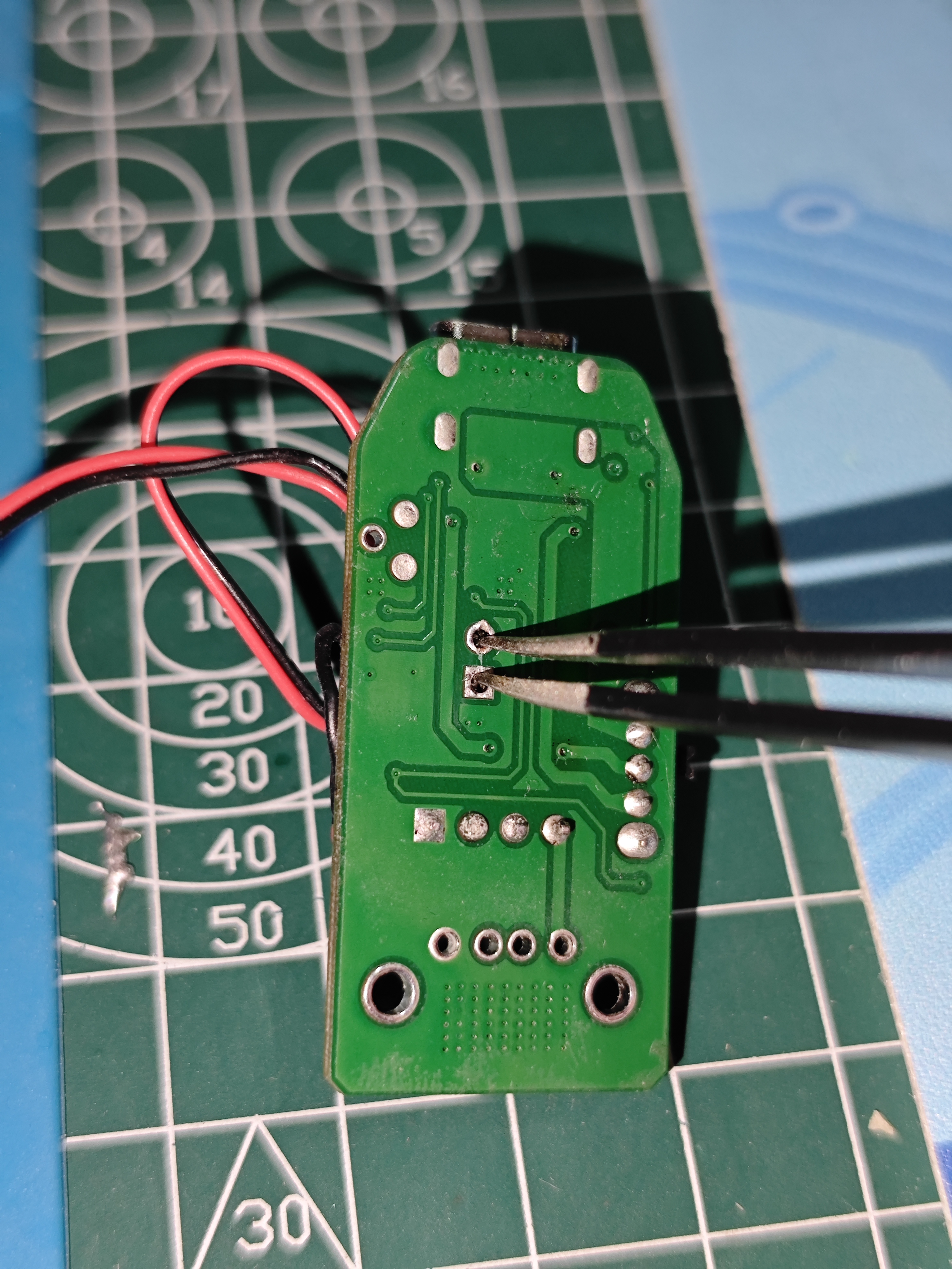
This is a classic boost circuit that provides a stable 20V output.
This is a classic boost converter circuit, providing a stable 20V output with a maximum output of 1.5A. A heatsink is required during use; avoid touching the heatsink while it is in operation. A 12V battery is recommended as the input power source; insufficient input voltage will cause the module to overheat. This circuit has been verified to function correctly.
WeChat image_20231025101027.jpg
551794984713b7efc9213ed55278e0af.mp4
PDF_Laptop Charger.zip
Altium_LaptopCharger.zip
PADS_Laptop Charger.zip
BOM_Laptop Charger.xlsx
95165
DPLink Students - Low-Cost Downloader
A low-cost DAPLink programmer with a ch32v203 controller that supports firmware flashing via USB.
The PCB design by this author has been modified and the circuit optimized.
 
Firmware address: https://github.com/XIVN1987/DAPLink.
The programmer with the ch32v203 main controller supports 3.3V-5V output switching. In addition to DAPLink downloading, it supports serial port (UART) downloading and debugging. The RXD pin is already pulled up in the software; if a hardware pull-up is required, solder resistor R14. If no pull-up is needed, soldering is not necessary (in most cases, it works without soldering). Through processing of the TXD and RXD pins, it can adapt to all serial port downloaders on the market, enabling button-controlled downloading (after clicking download in the software, pressing the button will start the download), facilitating debugging.
DAPLink (2).hex
PDF_DPLink students - Low-cost downloader.zip
Altium_DPLink students - Low-cost downloader.zip
PADS_DPLink students - Low-cost downloader.zip
BOM_DPLink students-low-cost downloader.xlsx
95166
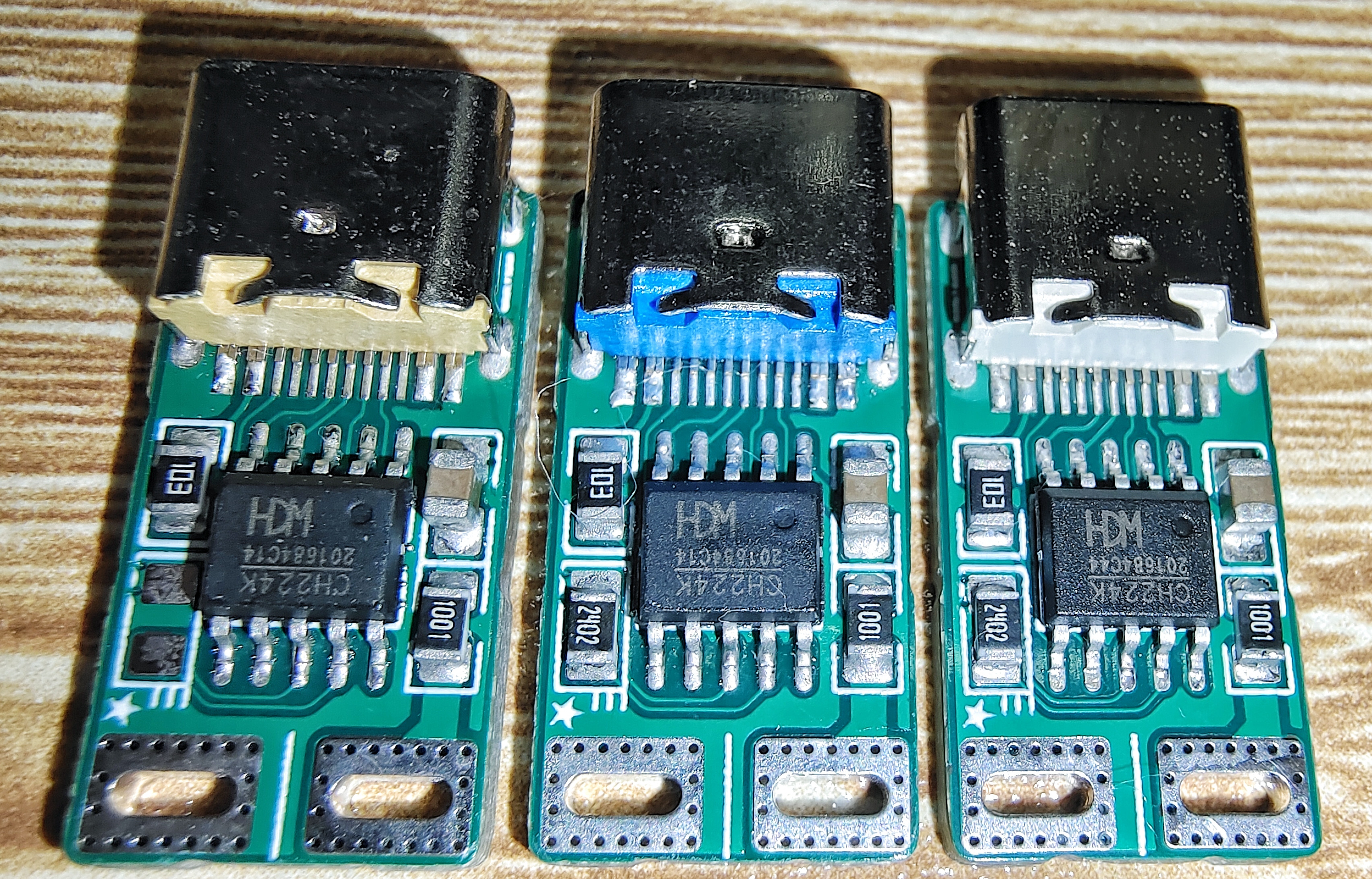
CH224K PD decoy board
The CH224K decoy board supports PD3.0/2.0, BC1.2 and other boost fast charging protocols.
Unauthorized commercial use is prohibited! If I catch you, I'll make sure you're haunted by nightmares, you'll be in big trouble!
 
CH224K Decoy Board
[Feel free to comment or message me with any questions about open source]
 

Function Introduction:


Interface: TYPE-C 16P female connector →→→ Large area soldering pads
Range: Maximum requested voltage level PD20V 
Onboard Chip: CH224K
Requested Voltage Levels: Supports PD3.0/2.0, BC1.2 and other boost fast charging protocols 9V 12V 15V 20V
How to Use: You need at least one charger that supports the PD protocol. Ensure the voltage selection resistor value is correct. Plug the charger's TYPE-C data cable into the decoy board's TYPE-C female connector. Then, CH224K will communicate with the charger via protocol. After a successful handshake, the VBUS pad will have the corresponding voltage level.


Update Log:


Project successfully verified.
Open source project released on 2023/5/9.


Notes on 2024/4/19:


6.8K=9V, 24K=12V, 56K=15V, NC=20V. The voltage level selection method uses single resistor configuration.
To ensure the PCB's current carrying capacity, I flattened the positioning posts of the [Component TYPE-C Female Socket], which prevents the VBUS traces from being blocked by the slots, resulting in a larger copper foil area.
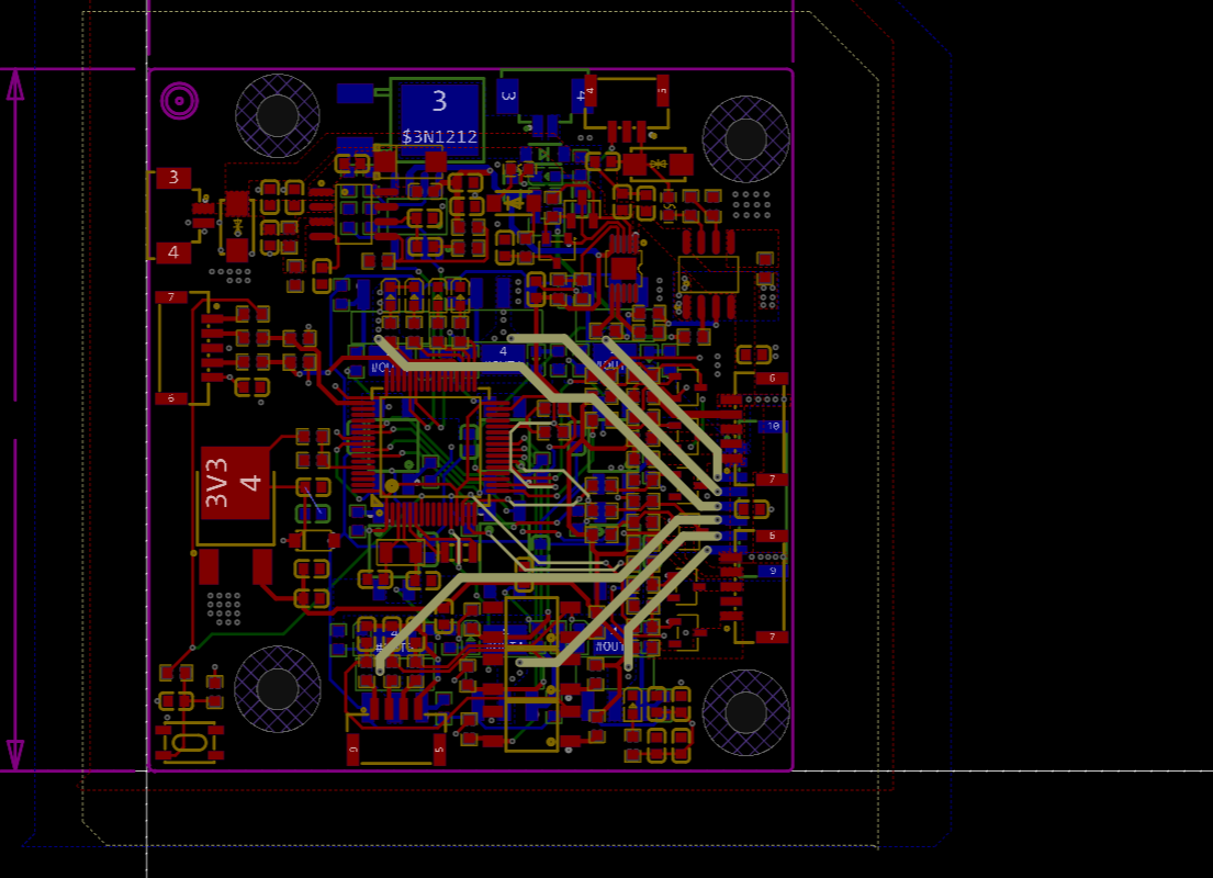
The PCB is a 4-layer board. With a 2-layer board, the GND return path is too thin; it can't pass through the top layer, and the bottom layer only has a tiny bit. Fortunately, it's a 4-layer board, with the inner 1 and inner 2 layers all used as GND to ensure sufficient GND return area.
Since I didn't adjust or modify the BOM, some components in the BOM directly generated by JLCPCB EDA may not match. It's best to carefully check the component names and values ​​on the schematic and PCB before purchasing.
The datasheet for the CH224K chip is included in the attachments on the open-source page. The image shows
 

               the TYPE-C female connector with its flattened positioning
posts (circled in red).
 
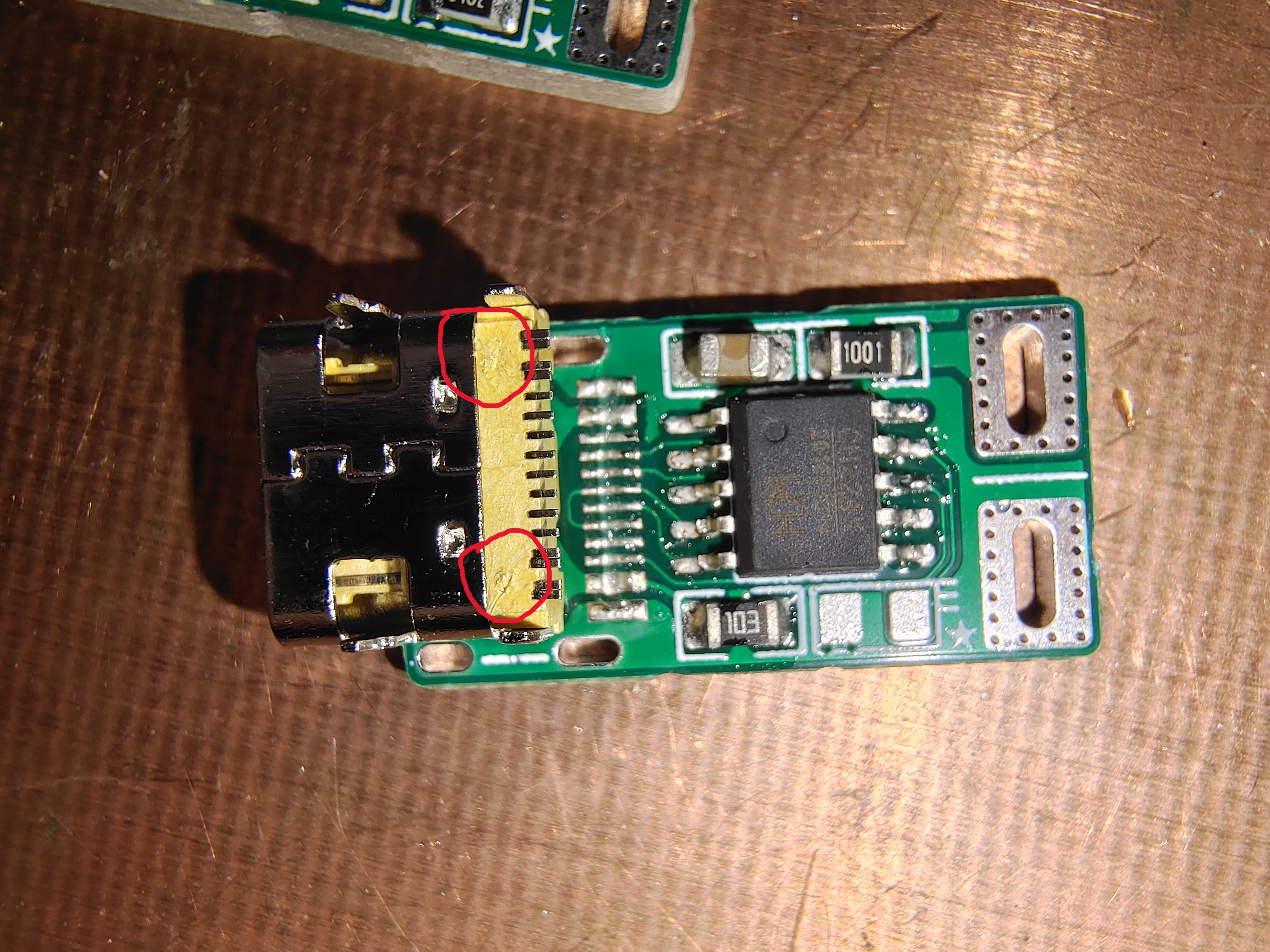
The component soldering details are also included.
 
 
CH224K USB PD and other fast charging protocol power receiving chip.pdf
PDF_CH224K PD Deception Board.zip
Altium_CH224K PD Deception Board.zip
PADS_CH224K PD Deception Board.zip
BOM_CH224K PD Deception Board.xlsx
95169
electronic
参考设计图片
×
 
 
Search Datasheet?

Supported by EEWorld Datasheet

Forum More
Update:2026-03-26 16:18:06
  • Problems with TTL NAND gate
  • wince的啟動問題
  • Tieto Recruitment: Embedded Software Engineer
  • Remote upgrade of HuaDa MCU HC32L110
  • Half of the computer monitor is black, please help me
  • Allegro SPB 16.5 version PCB drawing board quick course

EEWorld
subscription
account

EEWorld
service
account

Automotive
development
community

Robot
development
community

About Us Customer Service Contact Information Datasheet Sitemap LatestNews


Room 1530, 15th Floor, Building B, No.18 Zhongguancun Street, Haidian District, Beijing, Postal Code: 100190 China Telephone: 008610 8235 0740

Copyright © 2005-2024 EEWORLD.com.cn, Inc. All rights reserved 京ICP证060456号 京ICP备10001474号-1 电信业务审批[2006]字第258号函 京公网安备 11010802033920号