Note: This project has not been verified on a real motherboard. Replicating it requires caution, and I am not responsible for any losses incurred!
The power-on principle is the same as the screwdriver power-on method used by the author on the TuBa forum. The truly valuable parts of this project are the littlefs system and web page control.
(
After reading the summary, you don't need to read the rest.
) The code is open-source on GitHub: github-ESP32 Desktop Remote Power-On Card. You can also download the code directly from the attachment at the end of this document. This project was an assignment for my freshman project course. I am grateful to Professor Yan for her guidance; her practical engineering experience was very useful. This power-on card can achieve remote power-on within a local area network (it can connect to the ESP32's 2.4G hotspot to enter the console, or allow the ESP32 to connect to a specified router; entering the assigned IP address in the router's network will also allow access to the console). The power-on card can acquire temperature and humidity data through the AHT20 sensor and upload it to the network console and TFT screen.
I. Project Research Background
1.1 Problem Analysis
The inspiration for this project came from my classmate who deployed a server at home and wanted to use it at school, but currently lacked a simple solution for remotely powering on computers. Remote power-on cards for computers have appeared on the market to solve the problem of remote power-on of computers, but these products are still imperfect. The main disadvantages are: (1) lack of working indicator lights, and the status cannot be read directly on the power-on card. (2) single power supply method. (3) cannot detect the temperature inside the chassis. (4) expensive. Last August, the price of power-on cards was still very expensive, but by the time I made this product, the price of power-on cards on the market had dropped to more than 20 yuan.
1.2 Research focus
(1) Computer power-on method
(2) How to power on the power-on card
(3) Remote control and temperature monitoring
2.3 Application scenario
Choose one of the following two power supply methods, and do not use them at the same time!
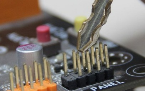
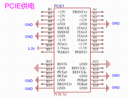
Method 1: As shown in Figure 3, install it in the PCIE slot of the motherboard, and use DuPont wire to connect the two power headers on the power card to the power headers on the motherboard.
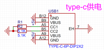
Solution 2: Use type-c power supply. Most motherboards now still supply power to the motherboard USB port after shutdown. Connect one end of the type-c cable to the type-c port of the power-on card, and the other end to the USB port on the computer motherboard. Connect the two power header pins on the power-on card to the power header pins on the motherboard using DuPont wires (positive and negative are not important).
After powering on the card, connect your mobile phone to the WIFI "ESP32 Remote Power-On Card", password is 12345678. After connecting, enter 192.168.4.1 in your browser to access the control panel. Click "Power On" in the control panel.
II. Project Technical Solution
2.1 Overall Solution
2.1.1 Requirements Analysis (Functional Description)
The MCU used in this product is ESP32, and the development platform is VS Code + Platform I/O. The programming language is Arduino. A relay is used to isolate the power-on card circuit from the motherboard circuit, and the computer is powered on by the short-term closing of the relay. A DHT11 temperature and humidity sensor is used to measure the temperature and humidity inside the chassis (replaced with the more advanced AHT20 in the second version). The ESPAsyncWebServer library is used to connect the microcontroller to the network and a simple HTML5 webpage is built as the control panel. Users can configure the network, power on/off the computer, and obtain the temperature and humidity inside the chassis in the control panel.
2.1.2 Architecture Design
The system board is shown in Figure 5, and the software flowchart is shown in Figure 6.

Figure 5: System Board Figure
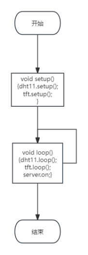
6: Software Flowchart
2.1.3 Platform Selection and Pricing
Module Name and Manufacturer Unit
Price
Quantity
Total Price
Espressif ESP32
20 yuan
1
20 yuan
1.8-inch TFT screen
13 yuan
1
13 yuan
DHT11 Temperature and Humidity Sensor
3 yuan
1
3 yuan
5V Relay
1.4 yuan
1
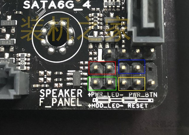
1.4 yuan PCB Board Thanks to JLCPCB 5 0 yuan 37.4 yuan 2.2 Sub-module 1: Computer Power-On Solution Figure 7: Power-On Jumpers on the Motherboard (blue box) The computer is powered on by shorting the two PWR jumpers (blue box in Figure 8). Powering on can be achieved by shorting these two pins with a relay for 0.5 seconds. The principle is the same as the screwdriver power-on method used by the user on the Tuba forum. 2.3 Sub-module 2: Power supply module solution . Most modern computer motherboards maintain power supply to the PCIe and USB ports when the computer is off. The PCIe interface has a fixed 3.3V output (B10 3.3Vaux in Figure 8), so there is no need to use a step-down module. The 5V voltage input to the Type-C power supply is stepped down to the 3.3V voltage required to drive the microcontroller and TFT screen using an AMS1117-3.3V voltage regulator chip. The step-down module is integrated on the PCB board. Figure 8: PCIe power supply. Figure 9: Type-C power supply. Figure 10: Step-down module schematic diagram. 2.4 Sub-module 3: TFT screen solution. A 1.8-inch TFT screen is selected for easy future upgrades to display more information and UI animations. Now that OLED screens have increased in price, TFT screens, which can display color and have larger sizes, are more cost-effective. The software uses the TFT_eSPI library, as shown in Figure 12. Figure 12: Importing the TFT_eSPI library into platformio. The complete code can be found in the attachment or on GitHub. Here is an excerpt of important code: #include // TFT screen display library. After downloading the TFT_eSPI library, you need to set the model to use in User_Setup.h #include #include "xfont.h" // Chinese display, thanks to https://github.com/StarCompute/tftziku/tree/master/src XFont *_xFont; TFT_eSPI tft = TFT_eSPI(); // TFT display void tftsetup() { tft.init(); // TFT screen initialization tft.fillScreen(TFT_BLACK); // Set the background to black // tft.setCursor(0, 0); // Place the mouse at the screen origin


tft.setTextColor(TFT_WHITE); // Set font color
tft.setTextFont(4); // Set font
tft.setTextSize(3); // Set font size
tft.initDMA(); // Enable DMA for faster screen refresh
_xFont-
>DrawChinese(0, 0, "Console", TFT_GREEN); // Start displaying Chinese characters at (0,0)
tft.setCursor(70, 0); // Place mouse at (70,0)
tft.println(myIP); // Display APIP address on the TFT screen
The tft.print() and tft.printf() functions in the TFT_eSPI library are both used to print text on the screen, but they have some differences: The
tft.print() function is used to print text or a string representation of a variable. You can use it to print values of numbers, characters, strings, and other data types. It can accept parameters of different types and convert them to strings for display. For example, `tft.print(123)` will print the number "123", and `tft.print("Hello")` will print the string "Hello".
The `tft.printf()` function is a formatted printing function, similar to `printf()` in C. It allows you to use format strings and variables to construct the output. You can include special format specifiers in the format string, such as `%d` (integer), `%f` (floating-point number), `%s` (string), etc., and then pass variables of the corresponding types in the parameter list. For example, `tft.printf("Value: %d", 123)` will print "Value: 123".
`tft.println()` will add a newline at the end.
Displaying Chinese characters using the TFT_eSPI library is quite cumbersome. Initially, I referred to the video "Teacher Eva is Here" on Bilibili:
[ESP32+TFT Zero-Based Introduction to Chinese Character Display, A Comprehensive Tutorial from Software Download to Character Conversion, Open Source Code, Come and Learn!] https://www.bilibili.com/video/BV1yz4y1u7eV/?share_source=copy_web&vd_source=c91c35fde3c46c7e7f8e829ecd5674f9
However, the character encoding provided in this video is quite complicated, and the Chinese characters displayed on the TFT are not clear. The biggest drawback is that Chinese characters need to be encoded separately, which takes up a lot of storage space. A character library of 1150 Chinese characters requires 2.62MB of flash space, which is not friendly to the ESP32 with only 4MB of built-in flash. Later, I used the patch from https://github.com/StarCompute/tftziku/tree/master/src. This 7000-character font only requires 744KB and displays text clearly. You can refer to the readme and main.cpp on the website for how to use this library, but there are a few things to note.
1. This patch supports both the Arduino_GFX and TFT_eSPI libraries. If using the TFT_eSPI library, you need to uncomment `#define TFT_ESPI` on line 3 of `xfont.h` and comment out the line above it. The result after the change is as follows:
// Comment out the library to use here, select the direction on line 80, and select the direction on line 35 of `xfont.cpp`
// #define ARDUINO_GFX
#define TFT_ESPI
2. The screen rotates 90 degrees clockwise by default. If you want to select normal display, you need to swap the positions of `TFT_HEIGHT` and `TFT_WIDTH` on line 80 of `xfont.h`. The result after the change is as follows:
#elif defined(TFT_ESPI)
int screenHeight = TFT_HEIGHT;
int screenWidth = TFT_WIDTH;
#endif
and comment out line 35 of `xfont.cpp` // tft.setRotation(1);// Rotate 90 degrees clockwise to display
2.5 Submodule 4: AHT20 temperature and humidity sensor solution.
Simply import the AHTX0 library into platformio; sample code is included.
2.6 Submodule 5: Network console solution.
The network console uses HTML5 + ChatGPT to write
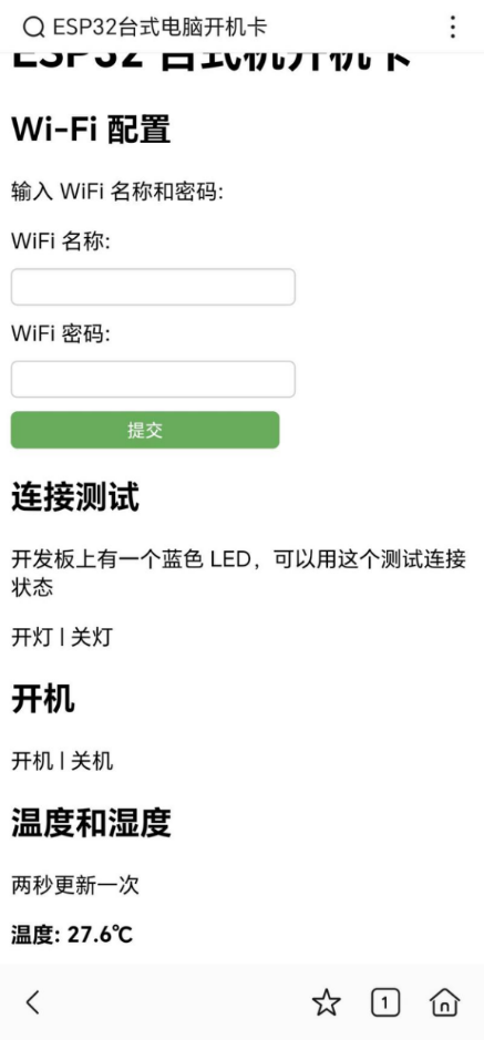
the console page home.html. The webpage effect is shown in Figure 4.
ESP32 desktop computer power-on card
Wi-Fi configuration.
After successful network connection, the hotspot will be turned off.
Enter the WiFi name and password:
WiFi name:
WiFi password:
Connection test.
There is a blue LED on the development board, which can be used to test the connection status.
Click to turn on the light
. Click to turn off the light. Click to
power on. Click
to power on.
Click to power off.
Temperature and humidity
are updated every two seconds.
Temperature:
Humidity:
When the user clicks the power button on the webpage, the webpage will jump to /ON (as shown in Figure 12). After the microcontroller receives the signal, GPIO13 outputs a high level for 0.5 seconds, causing the relay to close briefly, connecting POWER SW+ and POWER SW- on the motherboard. This causes the computer to boot up.
Pressing the power button on the webpage will simultaneously redirect to another webpage, wait for 3 seconds, and then return, preventing the user from accidentally pressing the button and sending multiple commands in a short period of time.
server.on("/ON", HTTP_GET, [](AsyncWebServerRequest *request)
{
switchmode = 1;
digitalWrite(control, HIGH);
delay(100);
digitalWrite(control,LOW);
request->send(LittleFS, "/wait.html"); // Display the received interface
});
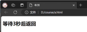
Figure 14: Returning to page
2.7 Submodule 6: littlefs file system
For the development of large-capacity devices, it is essential to establish a file system to realize the search, classification and management of files. Before using a file system, the code of home.html and wait.html web pages could only be merged in main.c, which was very inconvenient for viewing and modifying the code. If more complex web pages are created in the future, more HTML code and even images will be piled up in main.c.
After my research, the FS (file system) system is gradually being phased out and replaced by the littleFS system. The usage method is as follows, and you can also refer to the video 【【ESP8266】 How to use VScode + PlatformIO to upload files to the microcontroller FLASH flash memory and establish a LittleFS file system】
1. Add board_build.filesystem = littlefs in platformio.ini, as shown in Figure 14

Figure 15 Add littlefs in platformio.ini
2. Create a new folder named data in the project directory, as shown in Figure 15, and put the files to be burned into the data folder.
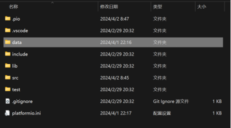
Figure 16. Create a new data folder in the project directory.
3. In the platformio console, first click "Build Filesystem Image". After compilation, click "Upload Filesystem Images" to upload to the microcontroller, as shown in Figure 16.
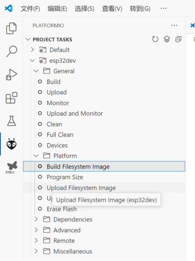
Figure 17. Compiling and uploading files in the file system.
The website code can then be placed in the data folder. Example of usage:
server.begin();
server.on("/", HTTP_GET, [](AsyncWebServerRequest *request)
{
request->send(LittleFS, "/home.html"); // Display the console interface
});
III. Verification and Test Results
The first version completed the website display and temperature data transmission. In the laboratory, it was tested with a DC power supply clamped to the corresponding PCIE pin, and the function was normal. The second version was upgraded. In the laboratory, it was tested with a DC power supply clamped to the corresponding PCIE pin, and the relay could switch. Inserting a Type-C power cable, the function was normal. I didn't dare to plug it into the motherboard to test the power-on.

Figure 18: First version physical display.
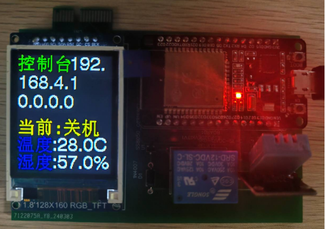
Figure 19: First version physical display

. Figure 20: Second version
physical display. Figure 19: Second version physical display
. IV. Summary and Outlook
This power-on card software was programmed using vscode + platformio. The hardware used JLCIC EDA to draw the schematic and PCB. It has been verified that the basic functions have been completed, but there are two points that need improvement: (1) Upgrade the control range from LAN to WAN. (2) Add practical functions such as history recording.
Although I found through further research that the computer can be remotely powered on through the WAN port (network) and does not need a power-on card at all, this project still has important practical significance. In the future, it can be integrated with fan controllers, RGB light controllers, chassis sub-screens, etc.
V. References
ESP32 Arduino Tutorial
Other remote power-on cards on LCIC Open Source Plaza


 京公网安备 11010802033920号

 1200SG3F029F24B


