1. Overview: This project aims to design and build a simple oscilloscope for displaying the waveform of input signals. The oscilloscope will acquire analog signals through a microcontroller and present the waveform graphics to the user in real time via an LCD screen. 2. Hardware Design:
1. Microcontroller: A GD32 microcontroller with sufficient processing power and rich library function support will be used as the main controller. 2. Analog Input: External signals will be received using analog input pins, and the analog signals will be converted into digital signals using an ADC (Analog-to-Digital Converter). 3. LCD Screen: A 128x64 pixel LCD screen will be used to display the waveform images in real time. 4. Power Supply: A suitable power supply circuit will be used to convert the power supply to the operating voltage required by the microcontroller and the LCD.
3. Software Design:
5. Signal Acquisition: GD32 standard library code will be written to configure the analog input pins and use the built-in ADC library functions to sample and convert the analog signals. 6. Waveform Display: Waveform images will be drawn on the LCD screen using graphics library functions. Basic graphics drawing algorithms can be used. 7. Interface Design: Design a simple and intuitive user interface, controlling the oscilloscope's operation via buttons or knobs, such as selecting the sampling frequency and adjusting the display range. 8. Signal Processing: Add signal processing functions, such as filtering, peak detection, and spectrum analysis, to enhance the oscilloscope's capabilities. 9. Communication Interface: Consider adding communication interfaces, such as UART, SPI, or I2C, for data exchange or remote control with computers or other devices.
4. Testing and Debugging: After completing the hardware and software design, perform system integration, testing, and debugging. Test the oscilloscope's performance by inputting different signal sources, adjust parameters, and resolve any potential problems to ensure the oscilloscope can accurately and stably display various types of waveform signals. 5. Summary: This simple oscilloscope provides an economical and practical way to observe and analyze analog signal waveforms, with good scalability and flexibility, allowing for functional expansion and improvement as needed.

PDF_#Training Camp#Oscilloscope.zip
Altium_#Training Camp#Oscilloscope.zip
PADS_#Training Camp#Oscilloscope.zip
BOM_#Training Camp#Oscilloscope.xlsx
95215
Dell Server Power Adapter
Dell Server Power Adapter
Conclusion: It's unnecessary to buy expensive connectors, but it's still a completely useless PCB.
A long time ago, while scavenging at a junkyard, I found a large batch of Dell servers and bought a few to play with.
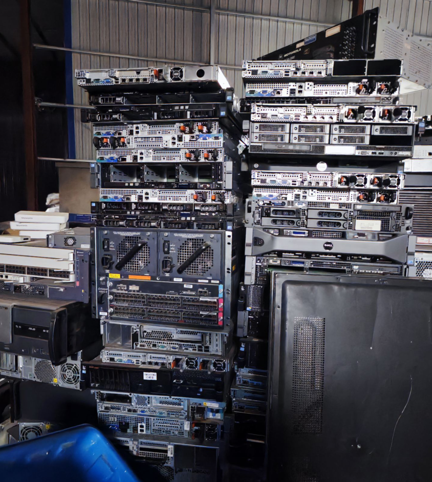
What kind of machines could you find at a junkyard? Most were R720 and R620. There weren't even any R710s; they must have been obsolete long ago…

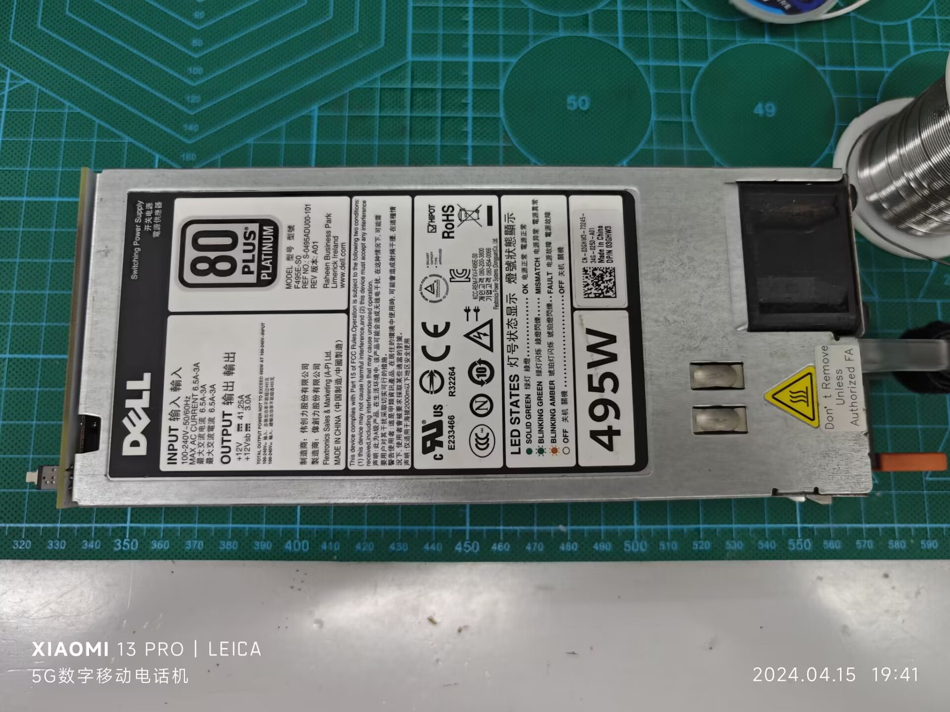
Thinking that server power supplies should be relatively stable, I got two power supplies, a 495W and a 750W.
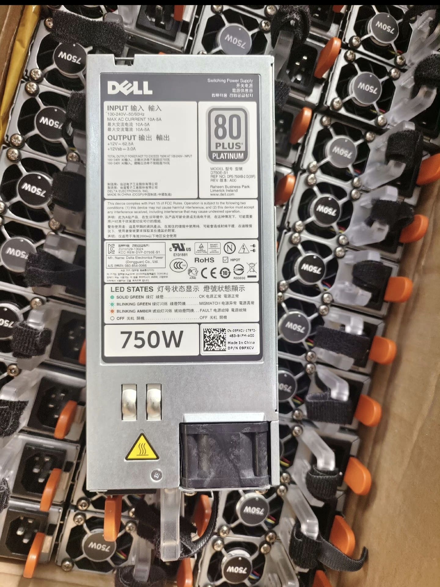
A very good power supply, which made my brain work.
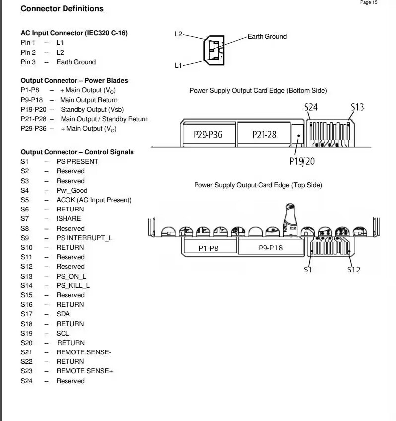
I searched on an open-source forum and found the pin definitions for this power supply (original link).
Then, JLCPCB EDA, boot up!

The PCB design is very simple, nothing much to say. Here's the diagram.

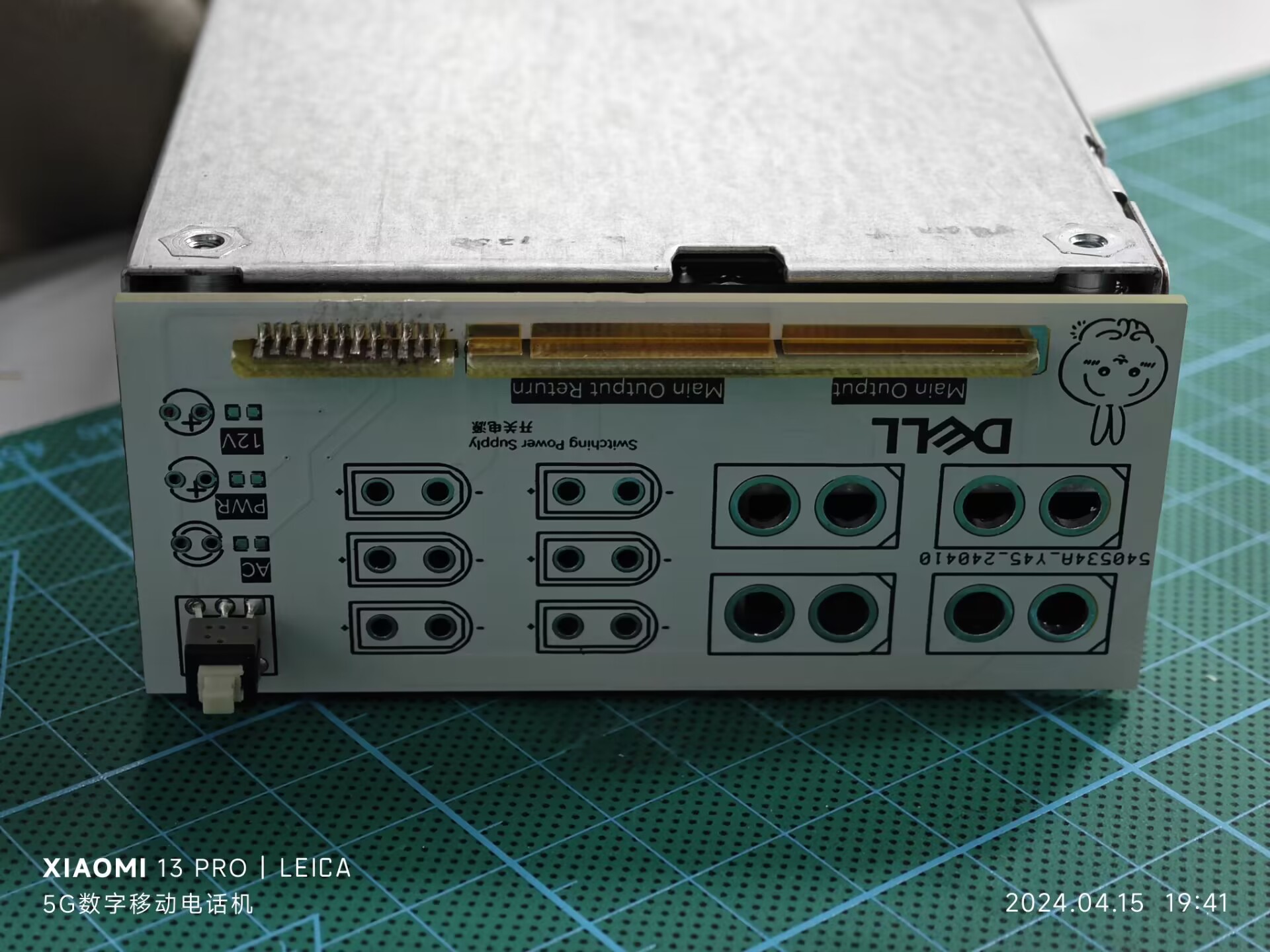
Well, that's it. Calling it completely useless is self-evident from the pin definitions; you just need to ground the two signal pins to run it…
Since you've read this far, a like wouldn't be too much to ask, right?

PDF_Dell Server Power Adapter Board.zip
Altium_Dell server power adapter board.zip
PADS_Dell Server Power Adapter Board.zip
BOM_Dell Server Power Adapter Board.xlsx
95217
XJOY_V1.1
Espressif BOX3 with matching remote control
Project Data
XJOY_V1.1 Project Data
PDF_XJOY_V1.1.zip
Altium_XJOY_V1.1.zip
PADS_XJOY_V1.1.zip
BOM_XJOY_V1.1.xlsx
95219
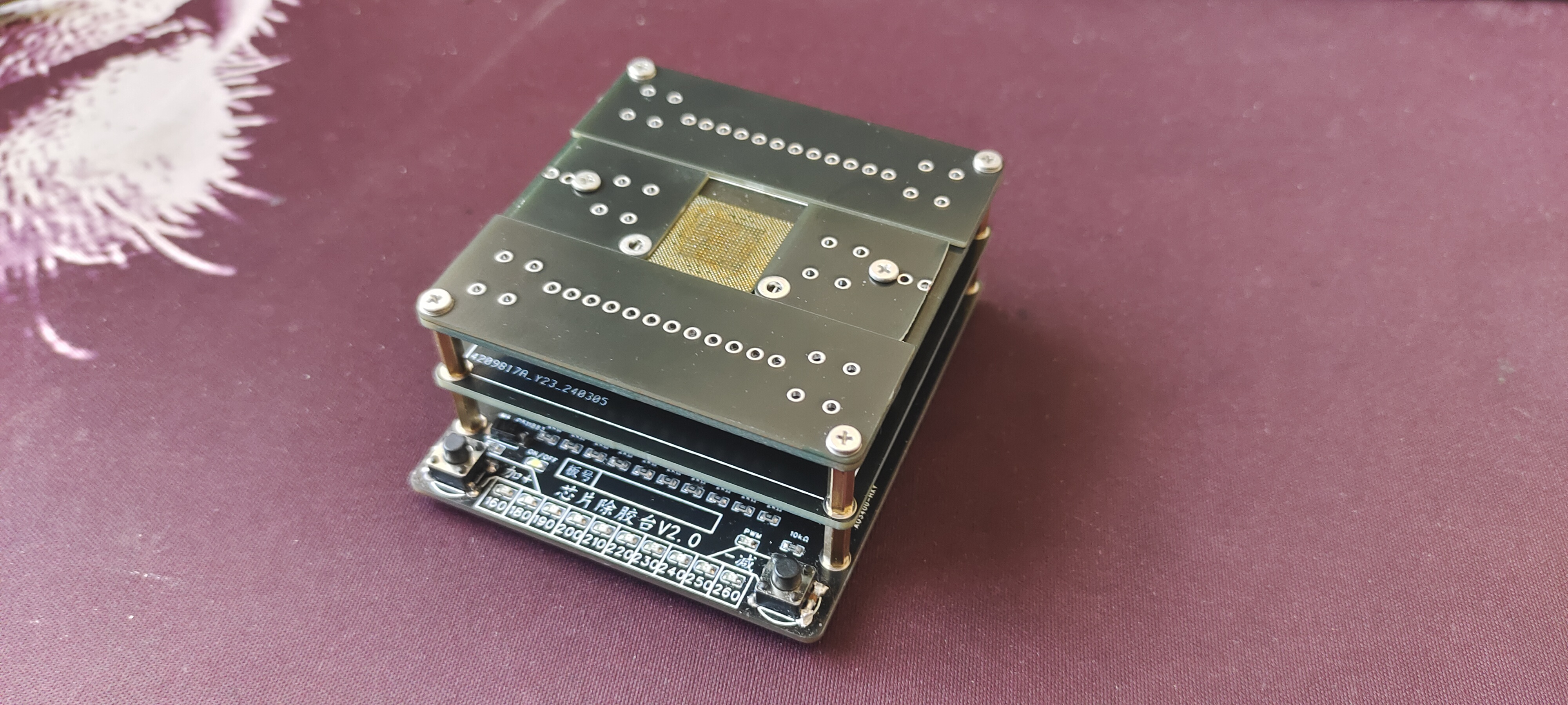
Basic chip adhesive removal station
Low-cost chip heating adhesive removal platform
I. Team Introduction:
Electronics enthusiasts
II. Design Summary:
51 microcontroller collects real-time temperature data from the heating plate; PWM controls heating.
III. Design Concept:
Thermistor collects real-time temperature data; PID algorithm is used to adjust the target temperature.
IV. Hardware Circuit Composition
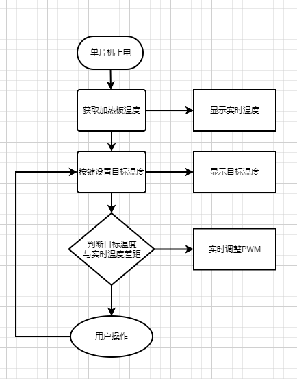
V. Program Flowchart
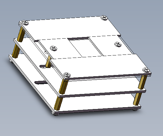
VI. Physical Demonstration
VII. Demo Video
: [DIY Chip Removal Station - Bilibili] https://b23.tv/PtDDjdc

VIII. Problems:
This is my first time using PID; I'm unsure if it's a programming or debugging issue. The temperature is unstable, and
sometimes there are accidental button triggers even after the button has been pulled down. Parallel debouncing capacitors don't work during testing. I don't know why; seeking expert guidance.
IX. Attachment:
Keil 5 source code
Glue Removal Station - Copy.zip
PDF_Basic Version Chip Removal Station.zip
Altium_basic chip desmearing station.zip
PADS_Basic Version Chip Removal Station.zip
BOM_Basic Version Chip Removal Station.xlsx
95220
electronic


 京公网安备 11010802033920号

 56111-G11-18-0500R


