I simply set up two sockets and placed a header pin in the middle to connect to the RP2040 for debugging the touch driver. Tutorial: https://blog.csdn.net/qq1003155077/article/details/130841838
It reads the PWM or PPM signal from the model aircraft receiver and connects to a specific MQTT server via Wi-Fi to remotely control the remote-controlled car.
This design draws inspiration from two open-source projects: "Xiaomozi's" "Potato Remote Control 4G Remote Control Car" (https://oshwhub.com/xiaomozi/tu-dou-fa-she-ji-3-0) and "LE12138's" "Le Remote Control 2.0 | RC Remote Control Converted to 4G Remote Control" (https://oshwhub.com/LE12138/1f51ac624d2742d7a845f79a25eda0b2)
, with slight hardware modifications.
The matching WIFI remote control receiver module is linked here: https://oshwhub.com/myself1820/wifi-yuan-cheng-yao-kong-mo-kuai-fa-she-he-jie-shou
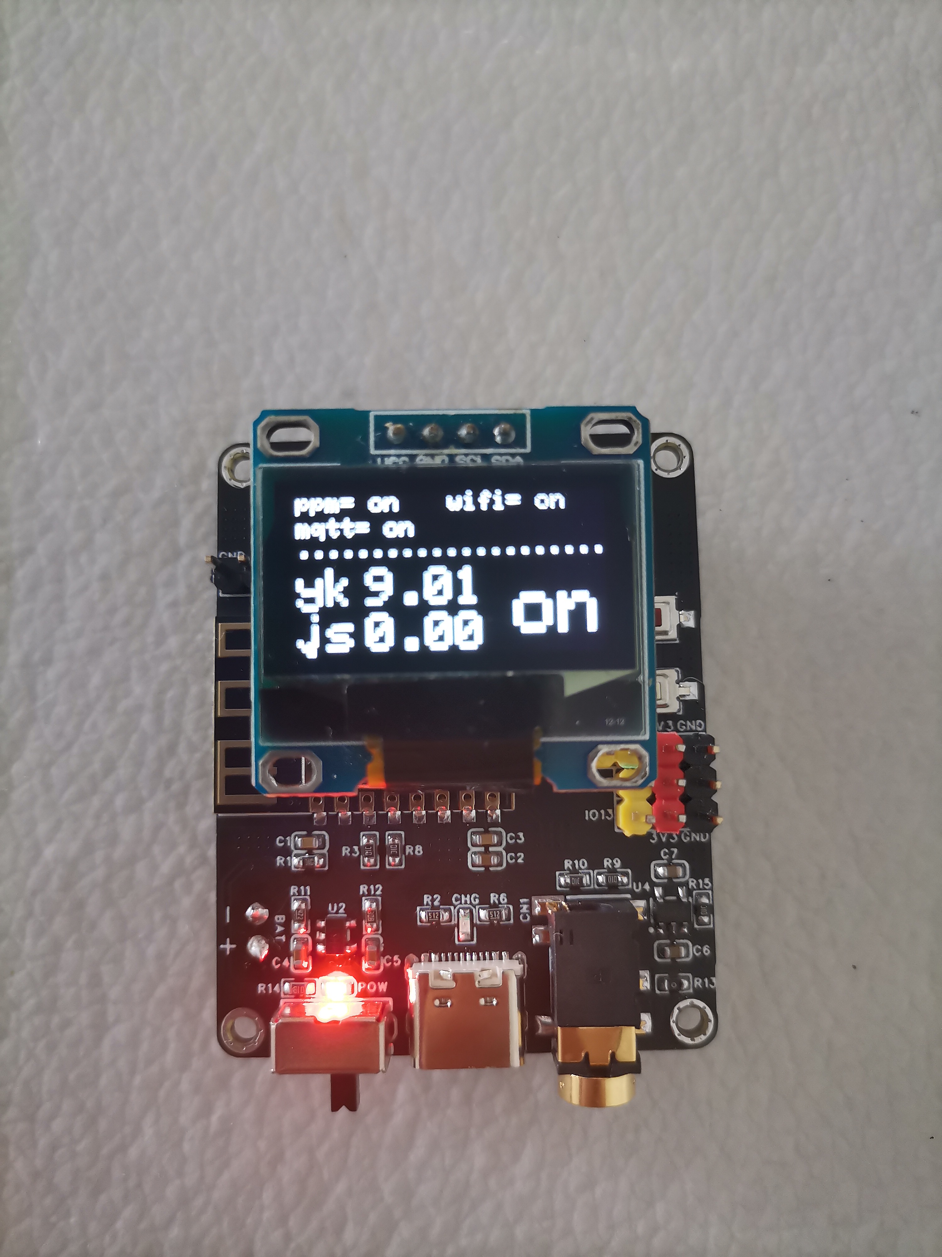
Main circuit functions
: (1) Integrated lithium battery charging circuit, 1S lithium battery power supply
(2) 3.5mm headphone jack for receiving PPM signal (corresponding to IO14 of 8266)
(3) All IO ports are brought out, and the PWM signal of the model aircraft remote control receiver can be connected in.
(4) Reserved serial port for downloading and debugging.
(5) Reserved I2C interface for connecting an external OLED screen
(6) Two onboard buttons, one is a reset button, and the other is used for network configuration (or other functions)
(7) 1-channel ADC for collecting battery voltage.
Project pictures


Other instructions
The program is directly burned into the potato remote control 4G remote control car code (remote control end) of the "xiaomozi" master mentioned above. I will not put it here.
Connect to a specific MQTT server via Wi-Fi to control the remote-controlled car.
This design draws inspiration from two open-source projects: "Xiaomozi's" "Potato Remote Control 4G Remote Control Car" (https://oshwhub.com/xiaomozi/tu-dou-fa-she-ji-3-0) and "LE12138's" "Le Remote Control 2.0 | RC Remote Control Converted to 4G Remote Control" (https://oshwhub.com/LE12138/1f51ac624d2742d7a845f79a25eda0b2)
, with slight hardware modifications.
The matching WIFI remote control transmitter module (8266 acquisition PPM) is linked here: https://oshwhub.com/myself1820/wifi-yuan-cheng-yao-kong-fa-she-mo-kuai-8266-cai-ji-ppm
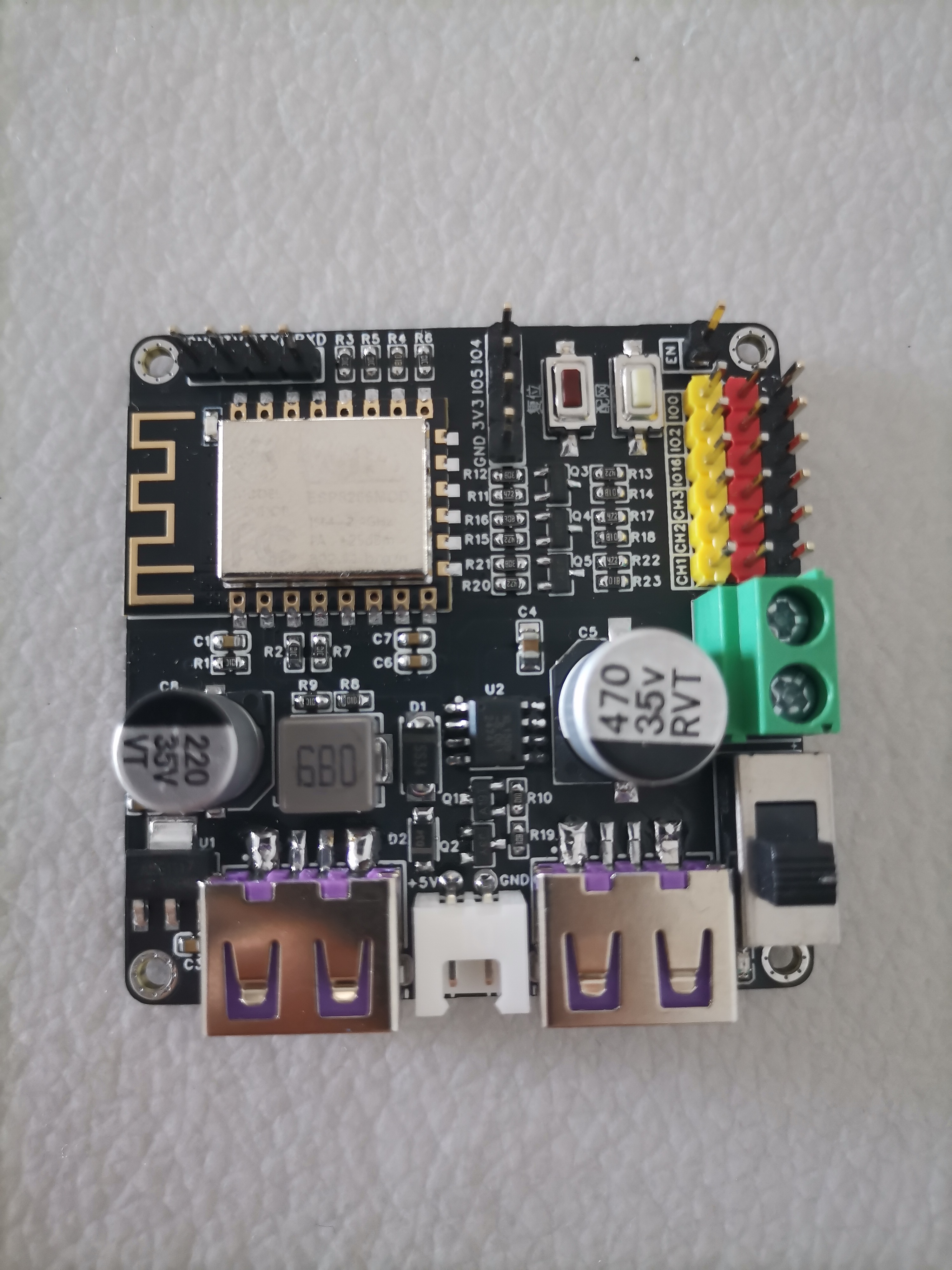
Main functions of the circuit
: (1) Integrated DC-DC voltage regulator circuit, which can be connected to an external 2-4S lithium battery;
(2) Two USB outputs of 5V power supply, used to power the wireless network card and wireless WIFI camera;
(3) All IO ports are brought out, among which IO13/CH1, IO12/CH2, and IO14/CH3 have added level conversion circuits, which can drive the ESC or directly drive the WS2812 light strip;
(4) Reserved serial port interface, which can be used for downloading and debugging, or connected to an external GPS module.
(5) Reserved I2C interface, which can be used as a normal IO port or connected to an external screen.
(6) Two buttons on the board, one is a reset button and the other is used for network configuration (or other functions).
(7) One 5V output terminal (controlled by IO15), which can be connected to an external 5V lamp group.
(8) One ADC to collect input power voltage.
Project pictures
Other instructions
The program is referenced from the potato remote control 4G remote control car code of the master "xiaomozi" mentioned above. You need to modify the IO port configuration in the program. I will not put it here. You can modify it yourself according to the schematic diagram.
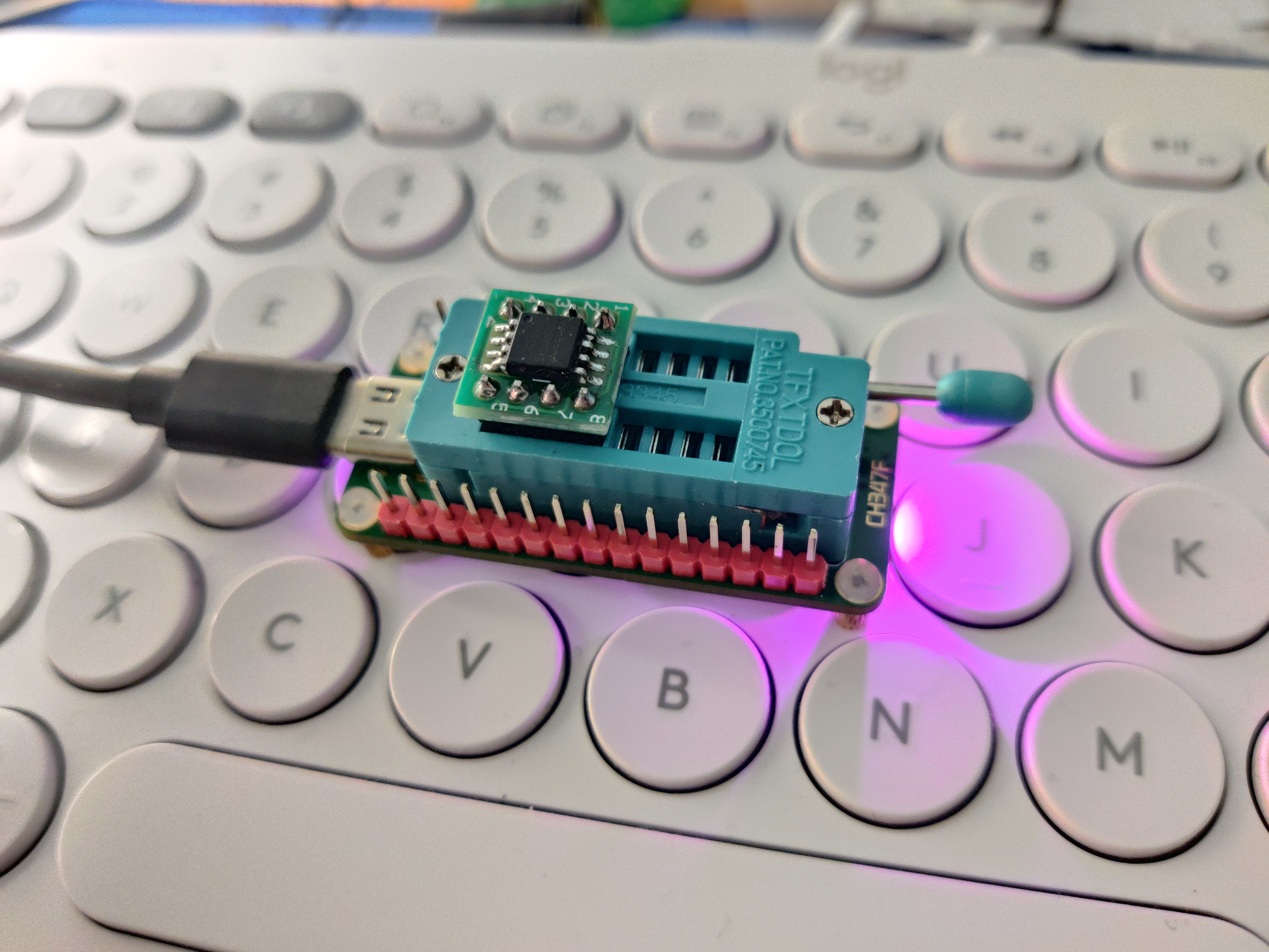
The
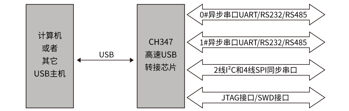
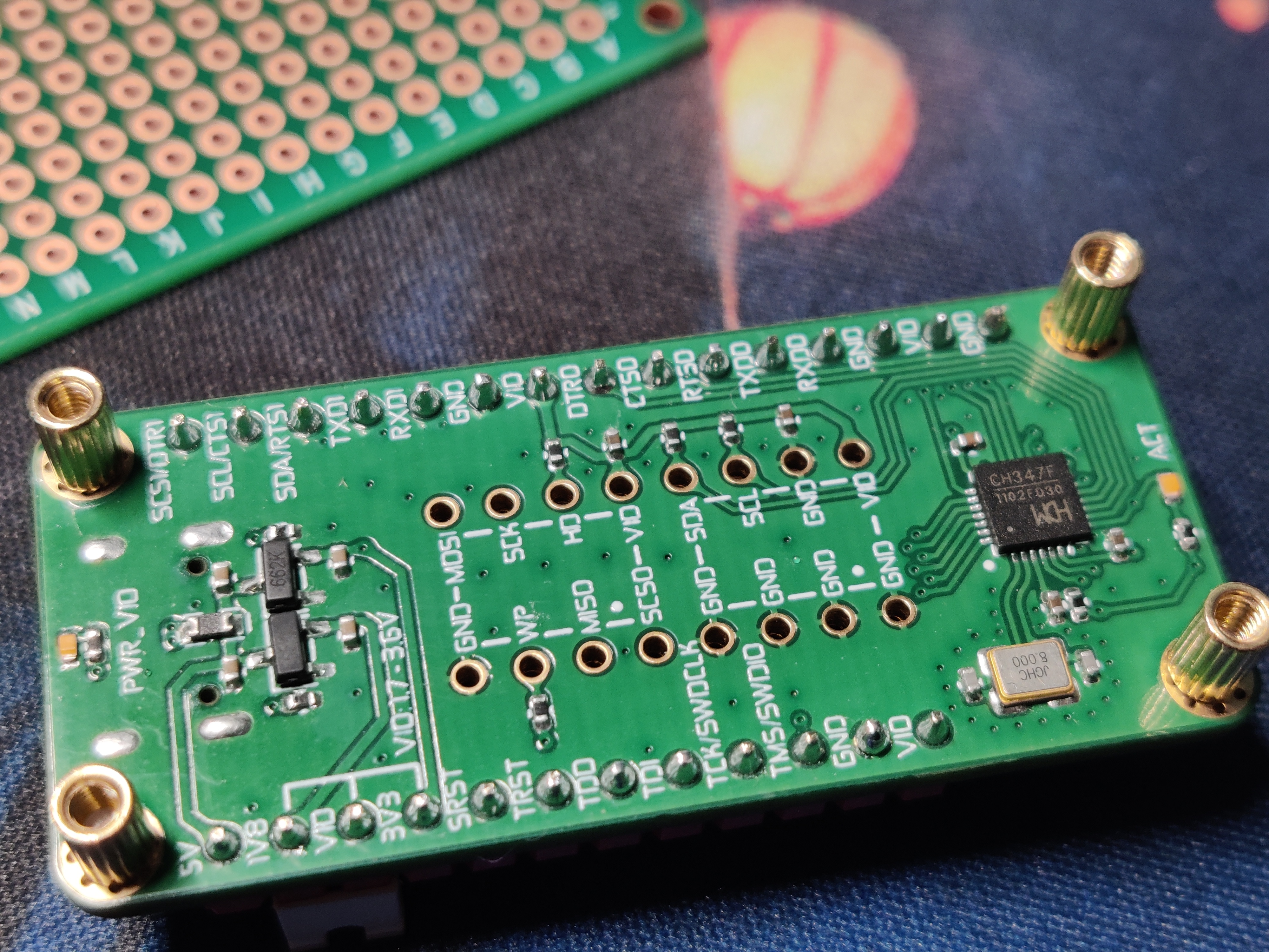
CH347 is a high-speed USB bus adapter chip that provides asynchronous serial ports, I2C synchronous serial interfaces, SPI synchronous serial interfaces, and JTAG interfaces via the USB bus.
In asynchronous serial port mode, the CH347 provides two high-speed serial ports, supporting RS485 serial port transmit/receive enable control, hardware flow control, and common modem handshake signals. It is used to expand asynchronous serial ports for computers or to directly upgrade ordinary serial devices or MCUs to the USB bus.
In synchronous serial interface mode, the CH347 provides one 2-wire I2C interface (SCL line, SDA line) and one 4-wire SPI interface (SCS line, SCK/CLK line, MISO/SDI/DIN line, MOSI/SDO/DOUT line). It is used to expand 2-wire or 4-wire synchronous serial interfaces for computers to operate EEPROM, FLASH, and sensors.
In JTAG interface mode, the CH347 provides one JTAG interface, supporting 4/5/6-wire interfaces (TMS line, TCK line, TDI line, TDO line, TRST line, and SRST line), used to expand the JTAG interface for computers and operate devices such as CPUs, DSPs, FPGAs, and CPLDs.
In SWD interface mode, the CH347 provides one SWD interface (SWDCLK line, SWDIO line), used to expand the SWD interface for computers and operate devices such as ARM MCUs and CPUs.
CH347F | CH347T Differences:
The CH347F supports independent I/O power supply, supporting 3.3V, 2.5V, and 1.8V power supply voltages.
The CH347F does not require configuration of operating modes and supports high-speed serial ports, I2C, SPI, JTAG, and SWD interfaces. The functions of multiplexed pins can be switched and controlled through the driver.
The CH347T chip configures its operating mode by detecting the voltage levels of the DTR1 (PIN10) and RTS1 (PIN13) pins during reset.
See the official manual for details: https://www.wch.cn/products/CH347.html.
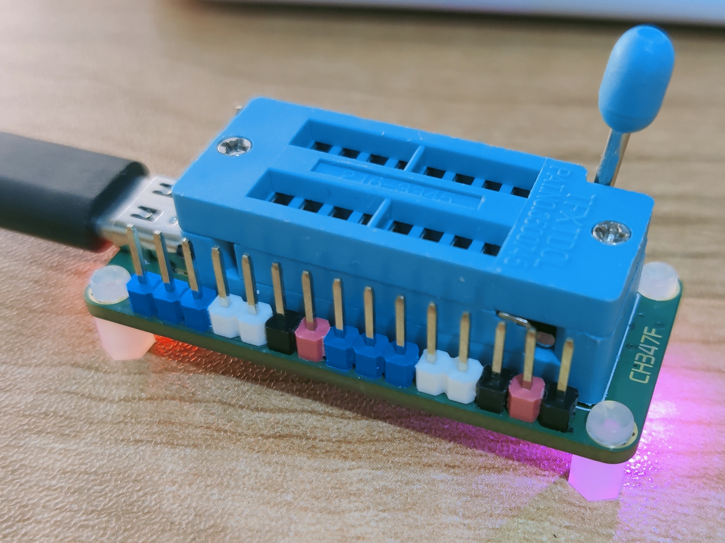
This uses
@hackpascal's open-source project https://github.com/hackpascal/ufprog. The latest version of the compiled file, CH347Demo.exe, is attached. A physical image of
the CH347Demo.exe from Qinheng is also included.
ufprog-build-2024-04-03.zip
PDF_CH347F Multi-Voltage Programmer (UART+I2C+SPI+JTAG+SWD Debugger).zip
Altium CH347F Multi-Voltage Programmer (UART+I2C+SPI+JTAG+SWD Debugger).zip
PADS_CH347F Multi-Voltage Programmer (UART+I2C+SPI+JTAG+SWD Debugger).zip
BOM_CH347F Multi-Voltage Programmer (UART+I2C+SPI+JTAG+SWD Debugger).xlsx
95399
Single-phase surge protection module
Single-phase surge protection module
As the title suggests, a ground wire must be connected; otherwise, lightning protection will be ineffective.
PDF_Single-phase surge protection module.zip
Altium Single-Phase Lightning and Surge Protection Module.zip
PADS_Single-phase surge and lightning protection module.zip
BOM_Single-phase surge and lightning protection module.xlsx
95400
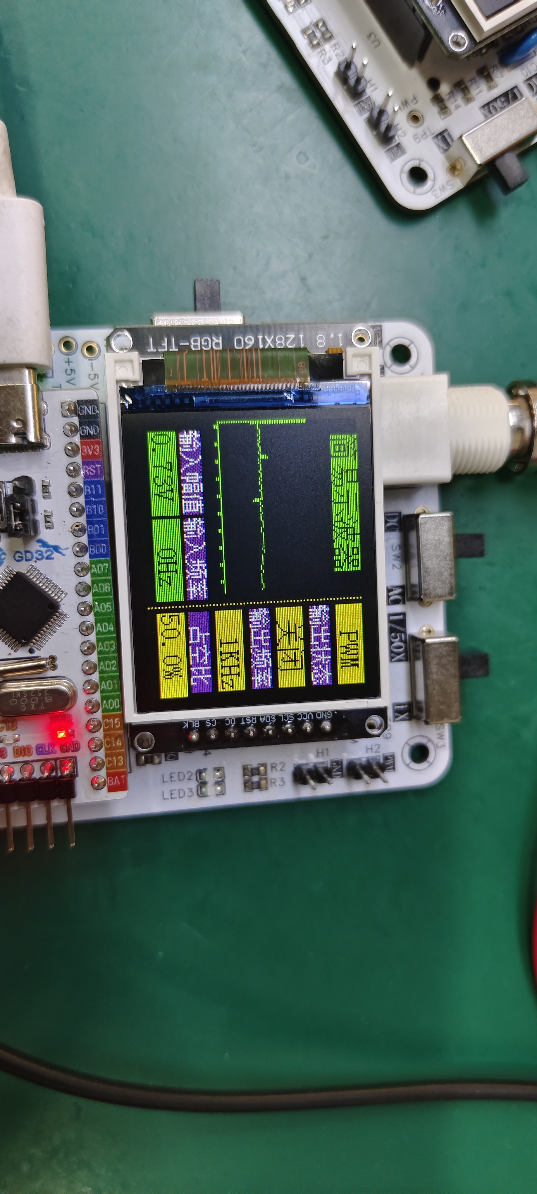
A simple oscilloscope project based on GD32
A simple oscilloscope project based on GD32
This project is a simplified oscilloscope replica created by participating in JLCPCB's training camp.
JLCPCB video tutorial: Learn to make a digital oscilloscope step by step: Free training camp is now open! I used DAPLink to flash the code for this Bilibili
project. It's incredibly convenient to flash while debugging via serial port.
The oscilloscope's accuracy measurement up to 20kHz is no problem.
Let me explain: This project is simple, but the difficulty lies in the software code. Because it measures low frequencies, the hardware isn't very complex; it's already quite simple. There are tutorials on Bilibili, but the videos guide you through configuring each low-level driver. The final combination of all the oscilloscope functions requires you to write it yourself. I think JLCPCB did a great job on this step. They don't want everyone to follow the videos the whole time, as that might hinder their ability to think independently and practice. However, they also provided example code to help you learn coding strategies and style. The videos simply copy some code and briefly explain its meaning (the presenters in the videos understand this, as it would slow down the process otherwise, making it very beginner-friendly and easy to get started). I typed all my code by hand, configuring it step by step. Some parts are exactly the same and can be copied. When you encounter the configuration of structures or some functions that you don't understand, I strongly recommend that you check the GD32 firmware library function usage manual or datasheet. It will tell you how to configure the parameters in the structure and function. This will give you a deeper understanding of the underlying code. Okay, that's all for my rambling. Now let's get into the main
circuit analysis.
(1) Analog front-end processing circuit: It is responsible for processing the input detection analog signal and then giving it to the microcontroller for recognition. The specific circuit includes AC/DC coupling selection circuit, voltage attenuation circuit, signal processing circuit and frequency detection circuit. It is the core of the whole circuit.
(2) Power supply circuit: It is responsible for providing positive and negative power to the op amplifier and system power supply. It is the basis for ensuring the normal operation of the circuit.
(3) Microcontroller circuit: It provides the control core for the system and is responsible for the acquisition, processing and output of input signals.
(4) Human-computer interaction circuit: It is used to control the functions of the oscilloscope, including buttons, knobs, LEDs, display screen and other input and output interfaces. It provides the foundation for the development of oscilloscope functions.
This section only discusses some key
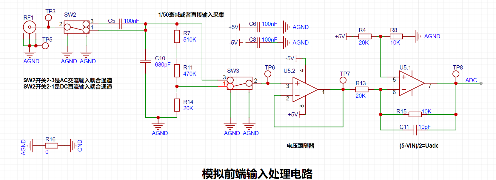
circuit diagrams. For RF1, I used a BNC to alligator clip cable, not a professional oscilloscope probe. I'm only providing a simple circuit analysis. SW2 implements two channels, AC and DC. For the AC input coupling capacitor, C5, the capacitance is 100nF. Larger capacitors pass low frequencies, smaller capacitors pass high frequencies. Its self-resonant frequency is 4MHz. Generally, the capacitor's cutoff frequency is required to be fc = (1/5) * fo, where fo is the operating frequency of the circuit. Therefore, 100nF is sufficient for this project. However, if the input signal frequency is higher, a smaller capacitor should be chosen.

The voltage attenuation is achieved by a series resistor voltage divider, calculated as 1/50. The formula is: 20K/(510K+470K+20) = 1/50.
When switches 2 and 3 of SW2 are connected together, the measurable input signal amplitude is -1.6V to 5V.
When switches 2 and 1 of SW2 are connected together, the measurable input signal amplitude is -80V to 250V.
I only have a power supply to collect the ADC output of 5V, but the actual measurement is as follows:
When switches 2 and 3 of SW2 are connected: It cannot reach 5V.
My power supply can only output a maximum of 32V. The attenuation measurement is as follows:
When switches 2 and 1 of SW2 are connected: Substituting into the formula, 32/50 = 0.64V.
The derivation of the subsequent amplifier circuit formula is as follows:

AGND and GND use 0-ohm resistors.
If you don't understand, you can refer to this website for learning: Why can a 0-ohm resistor separate the ground in a mixed digital-analog circuit? - Zhihu (zhihu.com)
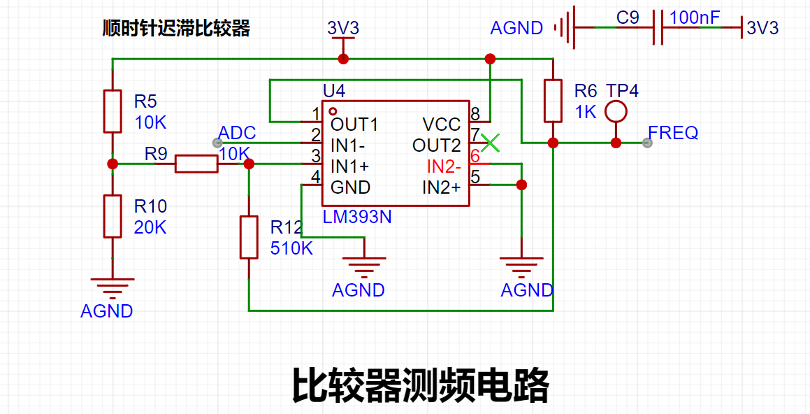
This is a hysteresis comparator. The microcontroller can easily acquire the frequency by using the input ADC output frequency.
When the output is high, the output terminal is pulled high, and Uth = U+ = 2.214V is calculated. When the op-amp output is low, the output terminal is grounded, and Utl = U- = 2.172V is calculated.
I don't think there's much to explain in this part; those who have studied op-amps already know this (but what if there are beginners who don't know?).
Here's a website for reference: Analog Circuits: Hysteresis Comparator - Zhihu (zhihu.com).
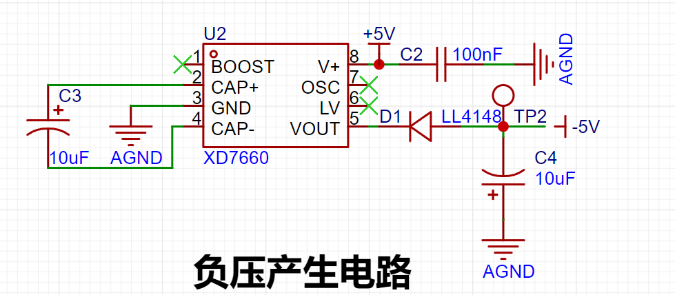
It uses the XD7660 negative voltage generation circuit to obtain a negative voltage. This chip has a simple external circuit, requiring only two capacitors and one diode to work. Theoretically, with an input voltage of +5V, it can also output a -5V voltage. Due to the internal voltage drop and conversion efficiency of the chip, the actual measured negative voltage is around -4.3V, which also meets the requirements of the operational amplifier. (The XD7660 D1 diode is not needed; I'm using a through-hole diode here.)
PCB Design Notes:
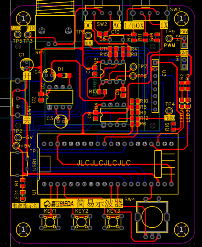
I'm using surface-mount resistors and capacitors.
Power lines are set to 20mil, and signal lines to 15mil.
Software Notes:
I've also included a simple oscilloscope code example below; you can refer to it if needed.
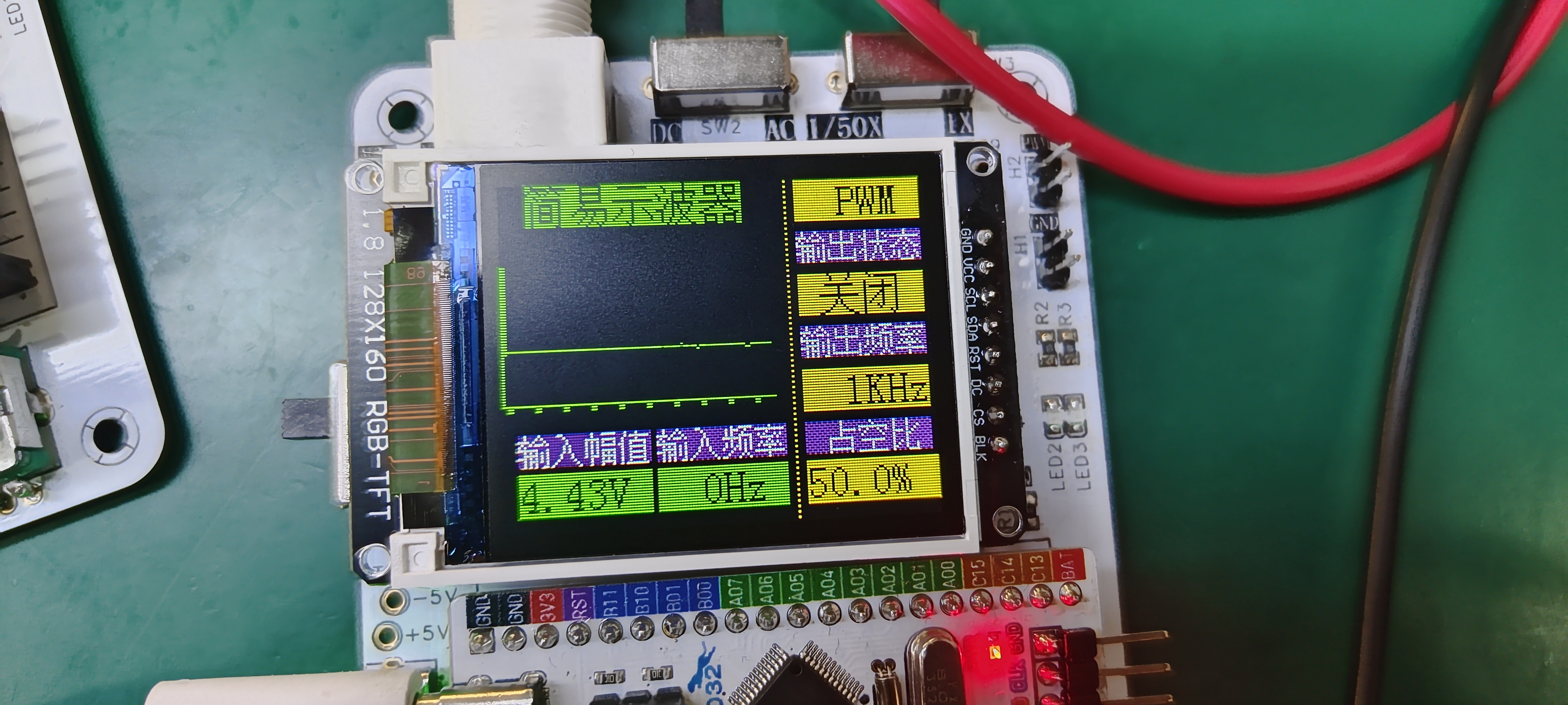
There's not much to explain about the code; you'll have to learn it yourself. Let me tell you about a screen display problem that requires modifying the LCD driver for
a 1.8-inch TFT screen. Many of you have probably encountered screen flickering. I also encountered this. At first, I thought it was a problem with the screen itself, but after asking some experts, they said it was a problem with the code's display address or origin.
I carefully looked at the LCD's example initialization and found a problem.
Before modification:
else if(USE_HORIZONTAL==2) { LCD_WriteCmd(0x2a);//Column address setting LCD_WriteData16(x1+1); LCD_WriteData16(x2+1); LCD_WriteCmd(0x2b);//Row address setting LCD_WriteData16(y1+2); LCD_WriteData16(y2+2); LCD_WriteCmd(0x2c);//Memory write }
Modified:
else if(USE_HORIZONTAL==2) { LCD_WriteCmd(0x2a);//Column address setting LCD_WriteData16(x1); LCD_WriteData16(x2); LCD_WriteCmd(0x2b);//Row address setting LCD_WriteData16(y1); LCD_WriteData16(y2); LCD_WriteCmd(0x2c);//Memory write }
After the modification, the screen displays normally
(I'm so annoyed!). Before the modification, various problems would occur. Originally, the yellow color on the far right would be displayed, but there would be a short yellow line or several yellow dots on the left. (
Image of the actual product )
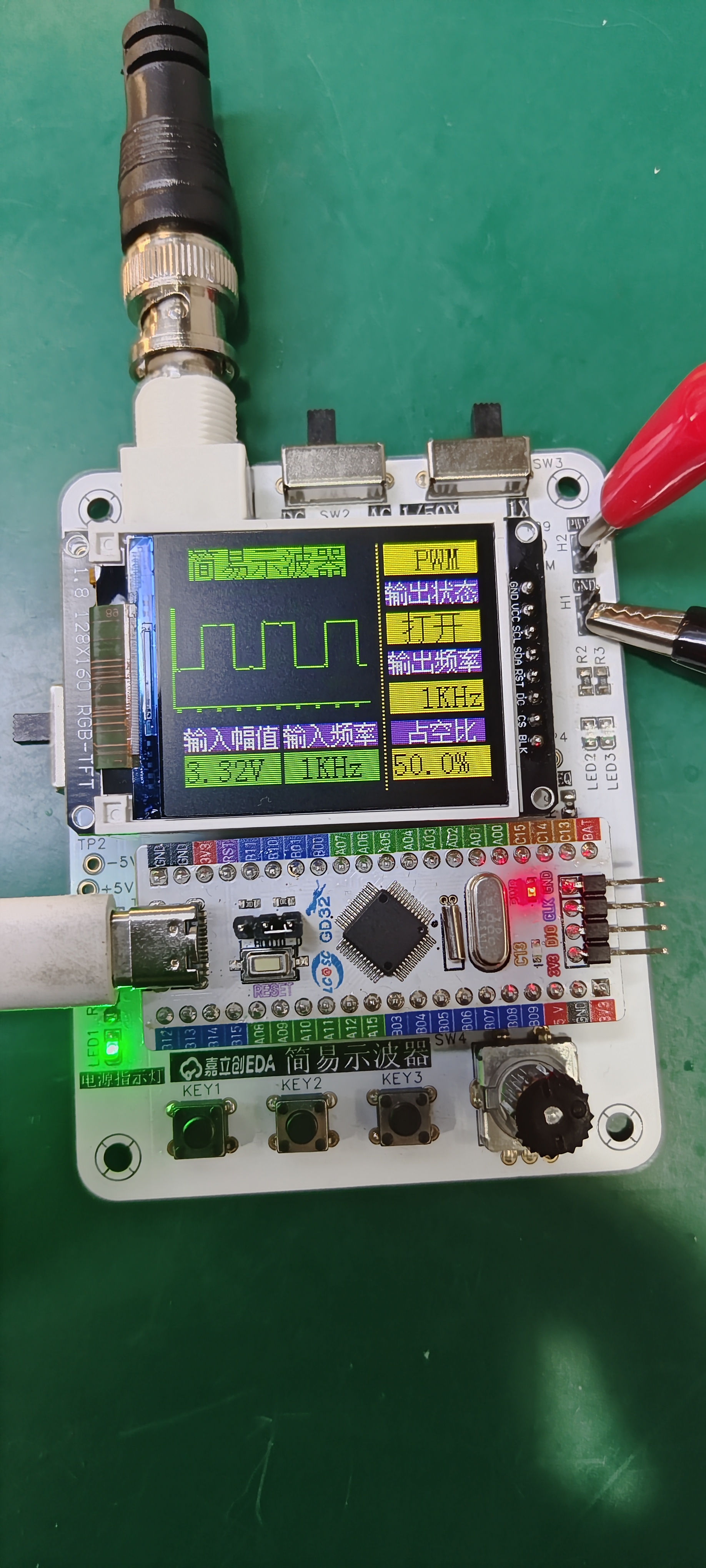
Using PWM to output 1kHz:
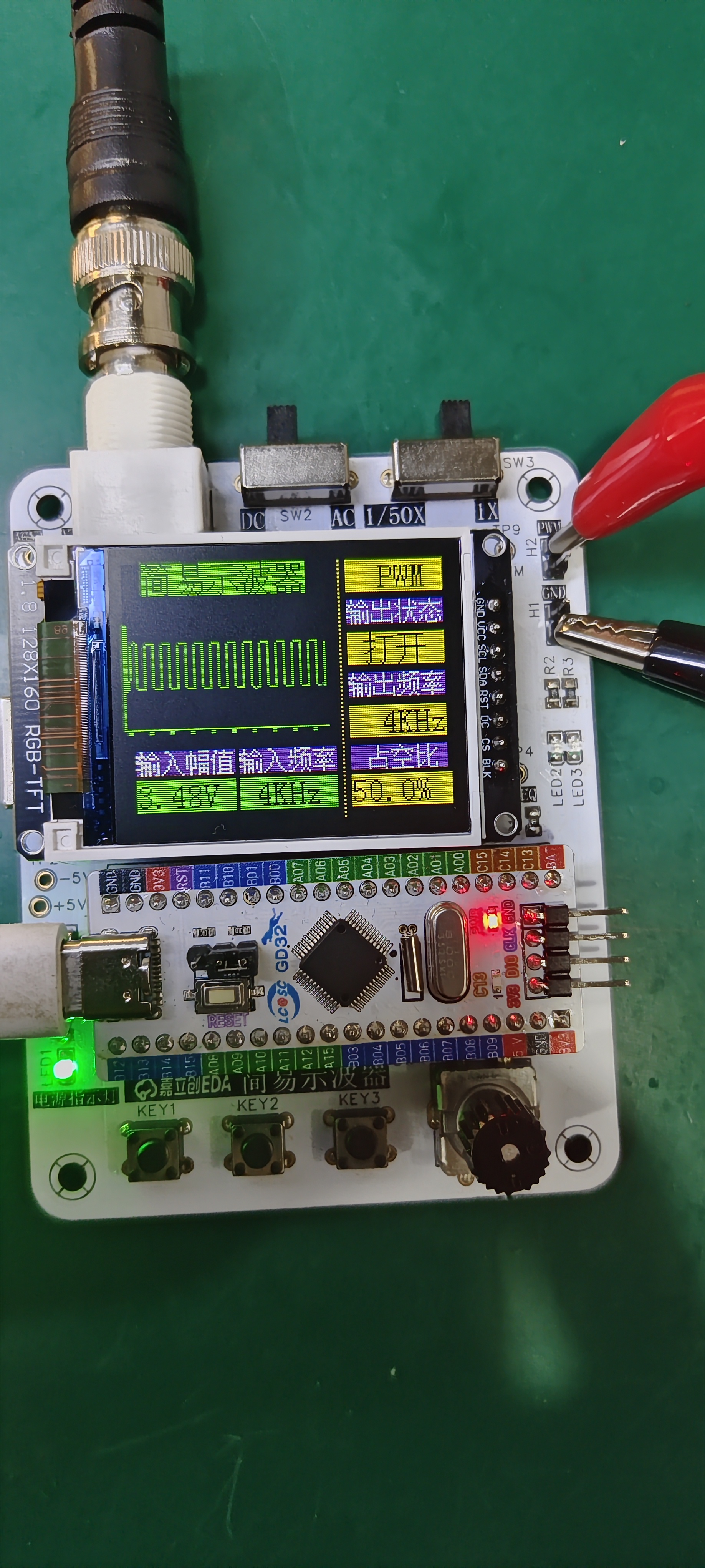
Using PWM to output 4kHz:
video_20240402_115726.mp4
Simple Oscilloscope Case Study.zip
PDF_Simple Oscilloscope Project Based on GD32.zip
Altium_GD32-based Simple Oscilloscope Project.zip
PADS_GD32-based Simple Oscilloscope Project.zip
BOM_Simple Oscilloscope Project Based on GD32.xlsx
95401
Simple Digital Oscilloscope
This is an oscilloscope based on the gd32c8t6.
The schematic should be fine, but the PCB layout is terrible. During the first test of the program, even without PWM, there was a 3V amplitude. I checked and found no cold solder joints, so I burned another program. However, I haven't had time to use the lab's pen for testing, so I've been putting it off. Also, my rotary encoder can only be turned up, not down. That's about it. This is a project I worked on for two weeks from scratch, and I think it's pretty good. I've basically mastered all the functions of the professional version. I'm looking forward to the next training camp.
PDF_Simple Digital Oscilloscope.zip
Altium Simple Digital Oscilloscope.zip
PADS_Simple Digital Oscilloscope.zip
BOM_Simple Digital Oscilloscope.xlsx
95403
Latest digital oscilloscopes
Simple Digital Oscilloscope
This simple digital oscilloscope, based on the domestically produced GD32C8T6 development board, outputs an adjustable frequency and duty cycle square wave signal via the PWM output function of the development board's timer. Then, through the voltage follower, proportional amplifier circuit, and comparator frequency measurement circuit on the expansion board, it achieves input voltage amplitude detection, adjustable voltage sampling attenuation ratio, and frequency measurement. Finally, the data is displayed on a 1.8-inch TFT screen.
WeChat image_20240402102111.jpg
Latest PDF Digital Oscilloscope (zip)
Altium Digital Oscilloscope Latest.zip
PADS Digital Oscilloscope Latest Version (zip)
BOM (Bill of Materials) for Digital Oscilloscopes (Latest Version).xlsx
95404
electronic


 京公网安备 11010802033920号

 CD137PX


