network NTP time synchronization system ; STA/AP dual-mode coexistence web page with customizable display colors and animation speed; Gitee open source address: Compass Clock Open Source.
A simple digital oscilloscope using an STM32F103C8T6 or GD32E230C8T6 minimum system board as the main controller, featuring a 1.8-inch TFT screen and a 3D casing. Since I didn't have access to a GD32, I used an STM32 as a substitute.
I participated in the LCSC training camp, where I built a simple digital oscilloscope using the STM32F103C8T6 or GD32E230C8T6 minimum system board as the main controller. It used a 1.8-inch TFT screen, and I learned about screen design and UI. From schematics to PCB layout to programming, LCSC guided us step-by-step, which was truly excellent. It helped me, who found ordinary EDA courses unbearable, learn the basic steps, and the finished product was quite good, even featuring a 3D casing. Since I didn't get the GD32 working, I used the STM32 as a substitute.
Oscilloscope Function Overview:
1. Switch: Powered by Type-C. Switch SW1 turns on the power, and button KEY3 starts the measurement.
2. Signal Selection: Switch SW3 switches between AC and DC coupling circuits to ensure accurate measurement of the input signal.
3. High/Low Voltage Range Switching: Adjust the voltage range using switch SW4.
Low voltage range: -1.6V~5V; High voltage range: -80V~250V.
4. Frequency measurement: Adjust the square wave signal range using button KEY2 and the duty cycle range using button KEY1.
It can output 1K, 2K, and 4K square wave signals, and the duty cycle can be adjusted via buttons.
5. Waveform amplification/reduction is controlled using a rotary encoder.
6. Waveform display: A 1.8-inch TFT color display shows the waveform, output status, output frequency, duty cycle, input frequency, and input voltage.
Hardware tutorial videos: https://www.bilibili.com/video/BV1uy421B7Ew/?spm_id_from=333.337.search-card.all.click&vd_source=ad14c6de5b549fa40091167d7615c437
Software tutorial videos: https://www.bilibili.com/video/BV1kw4m1o73g/?spm_id_from= 333.788.recommend_more_video.0&vd_source=ad14c6de5b549fa40091167d7615c437
This is a showcase of my own work (the 3D shell hadn't arrived yet): https://www.bilibili.com/video/BV1Cp421m7nW/?spm_id_from=333.999.0.0&vd_source=ad14c6de5b549fa40091167d7615c437
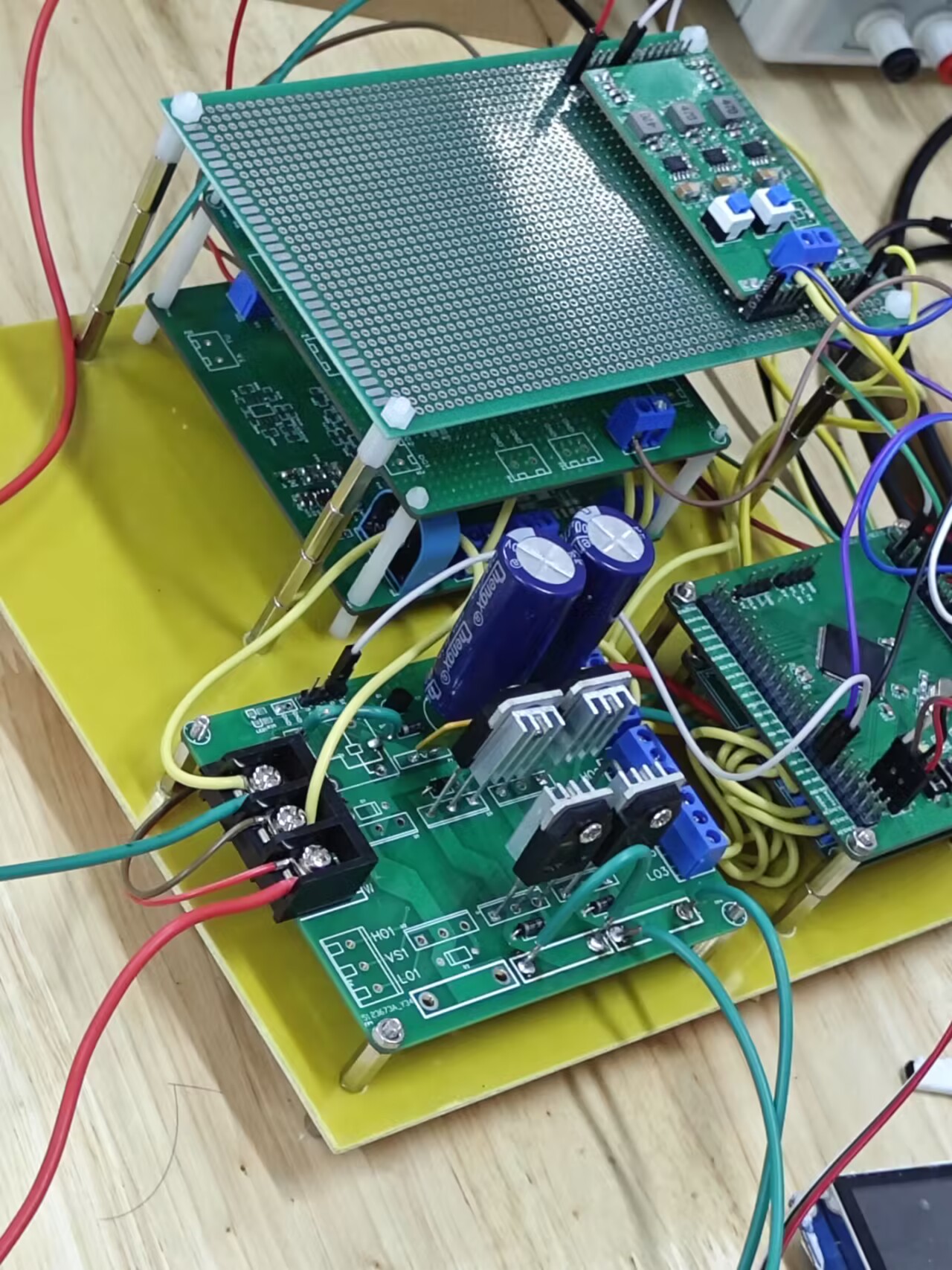
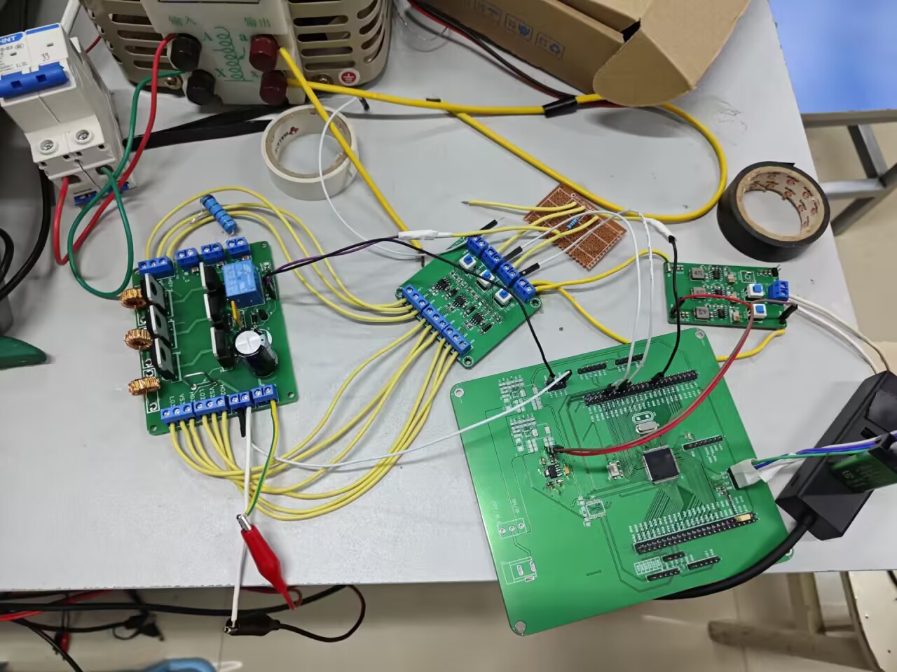
This article compiles information related to the 2023 National Electrical Engineering Competition's Single-Inverter Parallel System (Second Prize in Jiangxi Province). We only started preparing 10 days before the competition and ultimately won the second prize in Jiangxi Province. Keywords for this work include: SPWM wave inverter, H-bridge, STM32, voltage transformer, modulation ratio, IR2104S, etc.
The project was submitted for the competition in August 2023 and was subsequently collected by the school. Therefore, the physical prototype cannot be reproduced .
I was responsible for the software during the competition, so this section will mainly describe the software-related content in detail
. The software development platform was CubeIDE, and the hardware development platform was JLCPCB Professional Edition.
The software analysis includes
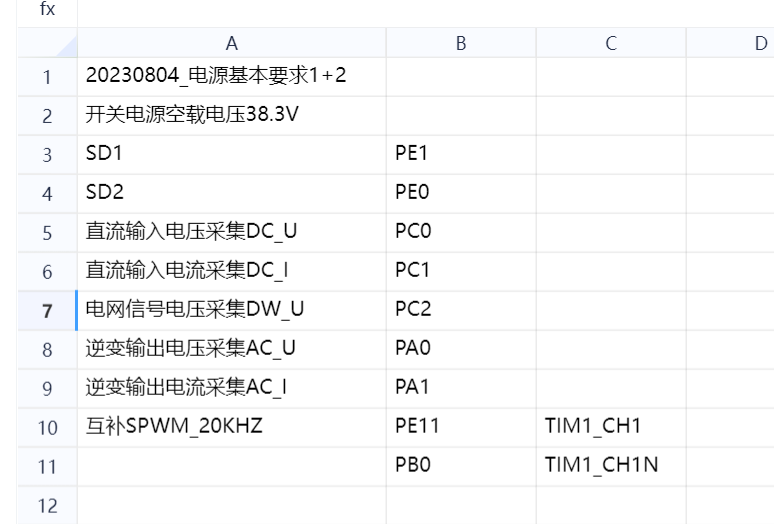
a minimum system board pinout diagram.
The core of the software part uses the output of the SPWM to control the switching transistors to achieve a full-bridge inverter. The SPWM is output through the microcontroller's advanced timer. To output the SPWM, a sine wave meter is needed, and the duty cycle of the advanced timer's PWM output is adjusted using the timer. By adjusting the SPWM modulation ratio, the amplitude of the final inverted voltage can be controlled. We can use hardware to proportionally reduce the inverted AC voltage and add a DC bias. Finally, the inverted AC power can be acquired by the microcontroller's ADC. The actual inverted result is calculated and corrected. Here, a professional instrument is needed to correct the coefficients. This coefficient is crucial; to achieve the accuracy required for the competition, the coefficients must be correctly corrected. Then, a PI controller is used to dynamically control the amplitude required for the competition. To accurately control ADC acquisition and reproduce inverter results,
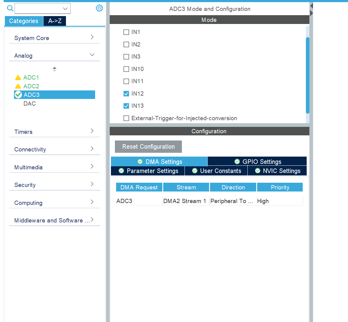
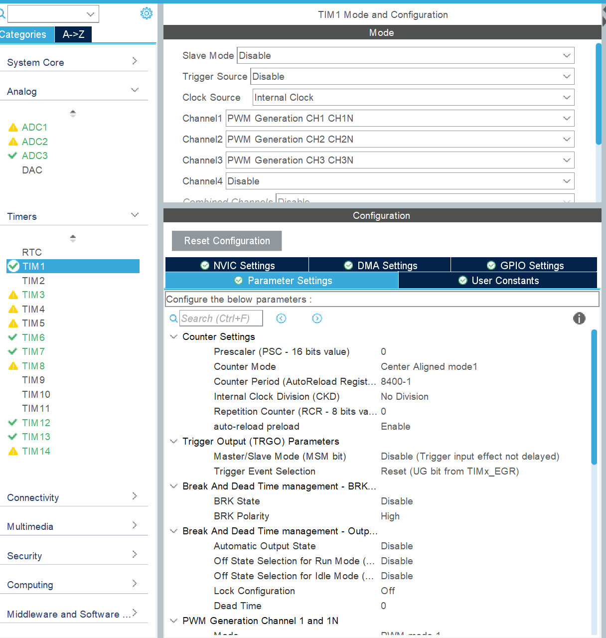
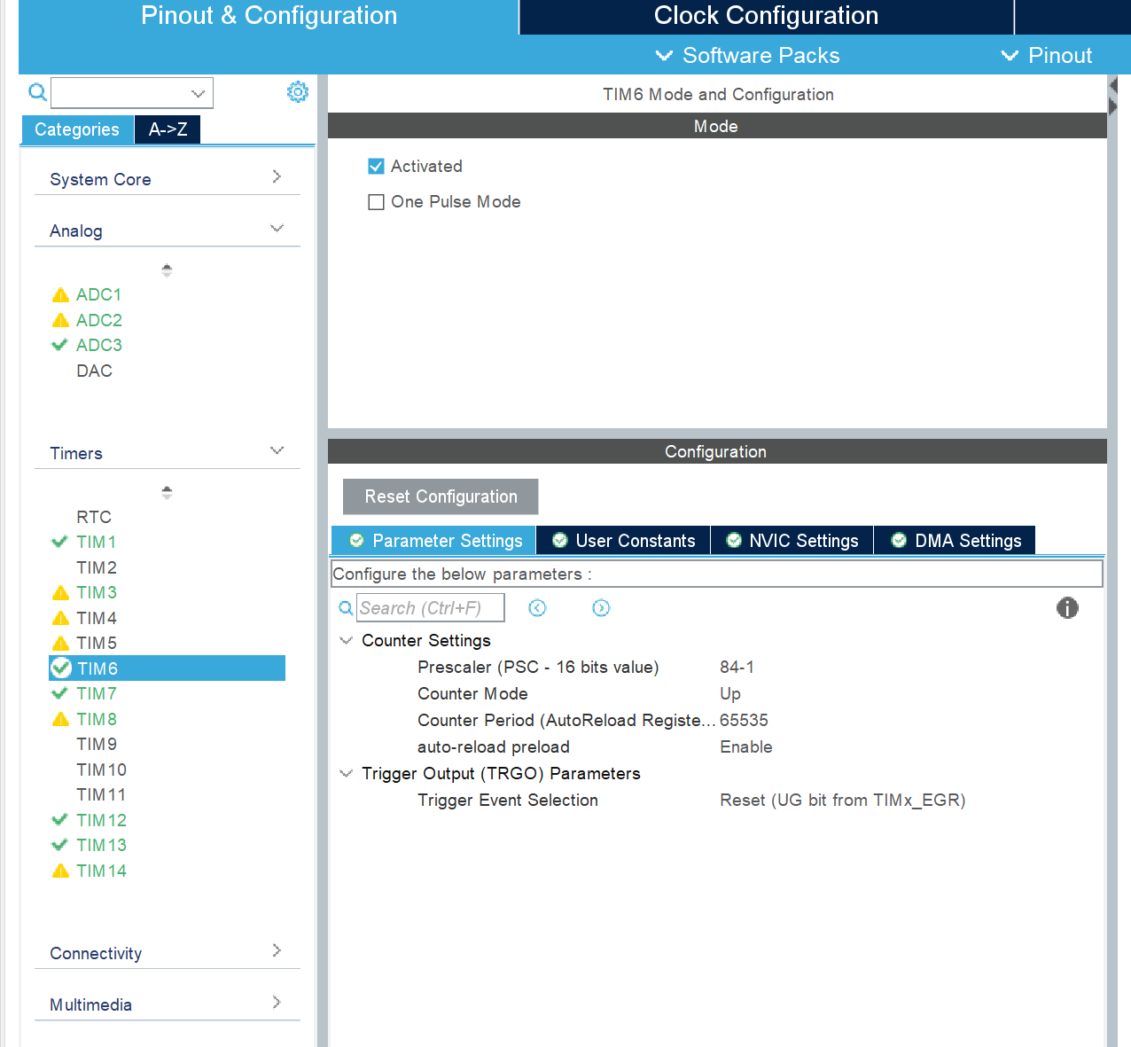
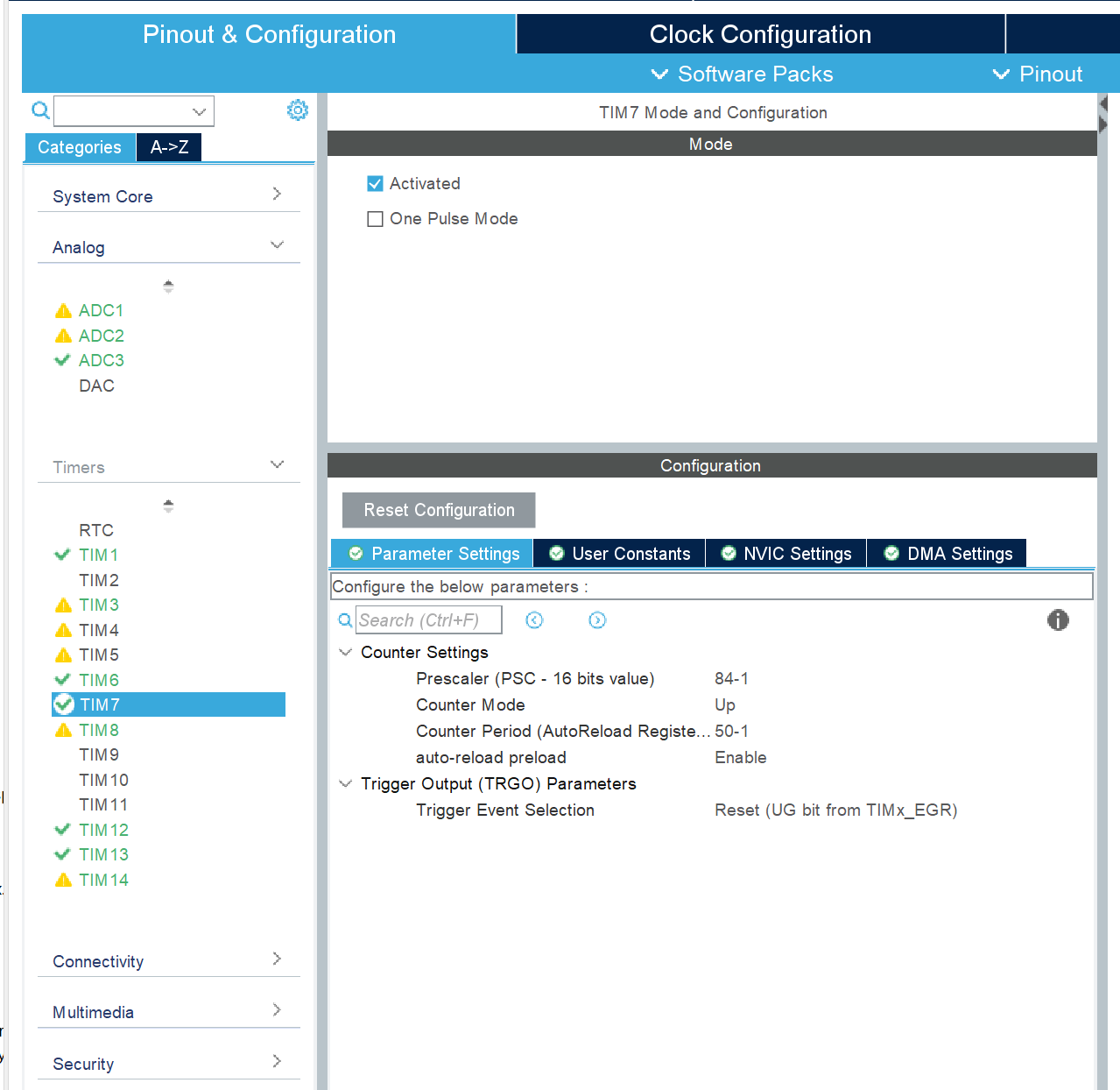
the ADC is configured with right-aligned data, scan mode, timer-triggered, and DMA used to transfer ADC acquisition data to improve efficiency. Timers are frequently used. Advanced timers output complementary SPWM, while ordinary timers implement microsecond (µs) delays. Timers can be used to implement sinusoidal duty cycles at 20kHz. Note that the operating frequencies of the STM32F407VET6 timers differ, as shown in the figure. When a timer interrupt occurs (timer 3 (htim3), a series of operations are executed: if (htim == &htim3) { /* * DC input voltage and current */ DC_U[Index_adc1] = 3.3f * ADC1_Value_DMA[2 * Index_adc1] / 4096; DC_I[Index_adc1] = 3.3f * ADC1_Value_DMA[2 * Index_adc1 + 1] / 4096; // arm_mean_f32(DC_U,400,&Udc_avg); DC_U[Index_adc1] = (DC_U[Index_adc1] >= 2.7)?2.7:DC_U[Index_adc1];//DC voltage limit maximum value DC_I[Index_adc1] = (DC_I[Index_adc1] >= 1.8)?1.8:DC_I[Index_adc1];//DC current limit maximum value Udc_temp += DC_U[Index_adc1]; Idc_temp += DC_I[Index_adc1]; if(Index_adc1 == 399){ Cycle++; if(Cycle == 3) Cycle_T = 1; Udc_avg = Udc_temp / 400 * UdC_K; Idc_avg = Idc_temp / 400 * IdC_K; Udc_temp = 0; Idc_temp = 0; } if (Udc_avg >= 60 || Idc_avg >= 10) { SD1(0); SD2(0); SD3(0); SD4(0); RedLed_on; } /* * Inverter current and voltage */ AC_U[Index_adc2] = 3.3f * ADC2_Value_DMA[2 * Index_adc2] / 4096; AC_I[Index_adc2] = 3.3f * ADC2_Value_DMA[2 * Index_adc2 + 1] / 4096; AC_U[Index_adc2] = (AC_U[Index_adc2] >= 2.52)?2.52:AC_U[Index_adc2];//Inverter voltage limit maximum value AC_U[Index_adc2] = (AC_U[Index_adc2] <= 1)?1:AC_U[Index_adc2];//Minimum inverter voltage limit AC_I[Index_adc2] = (AC_I[Index_adc2] <= 0.16683)?0.16683:AC_I[Index_adc2];//Minimum inverter current limit Uac_temp += AC_U[Index_adc2]; Iac_temp += AC_I[Index_adc2]; if(Cycle_T == 1){ AC_U_dc[Index_adc2] = (AC_U[Index_adc2] - Uac_avg) * UAC_K; AC_I_dc[Index_adc2] = (AC_I[Index_adc2] - Iac_avg) * IAC_K; RMS_Uac_U_temp += AC_U_dc[Index_adc2] * AC_U_dc[Index_adc2]; RMS_Uac_I_temp += AC_I_dc[Index_adc2] * AC_I_dc[Index_adc2]; }


if (Index_adc2 == 399) {
/*
* float RMS_Uac_U_N_1 = 0;
float RMS_Uac_U_N = 0;
float RMS_Uac_U = 0;
*/
Uac_avg = Uac_temp / 400;
Iac_avg = Iac_temp / 400;
RMS_Uac_U = sqrt(RMS_Uac_U_temp / 400);
RMS_Uac_I = sqrt(RMS_Uac_I_temp / 400);
Uac_temp = 0;
Iac_temp = 0;
RMS_Uac_U_temp = 0;
RMS_Uac_I_temp = 0;
}
if (Index_adc2 > 2) {
if ((AC_U_dc[Index_adc2] > 35 * 1.4142)
&& (AC_U_dc[Index_adc2 - 1] > 35 * 1.4142)
&& (AC_U_dc[Index_adc2 - 2] > 35 * 1.4142)) {
SD1(0);
SD2(0);
SD3(0);
SD4(0);
YelloLed_on;
}
if ((AC_I_dc[Index_adc2] > 3 * 1.4142)
&& (AC_I_dc[Index_adc2 - 1] > 3 * 1.4142)
&& (AC_I_dc[Index_adc2 - 2] > 3 * 1.4142)) {
SD1(0);
SD2(0);
SD3(0);
SD4(0);
BlueLed_on;
}
}
/*
* Grid voltage
*/
DW_U[Index_adc3] = 3.3f * ADC3_Value_DMA[2 * Index_adc3] / 4096;
DW_U[Index_adc3] = (DW_U[Index_adc3] >= 2.7)?2.7:DW_U[Index_adc3];//Maximum grid voltage limit
DW_U[Index_adc3] = (DW_U[Index_adc3] <= 0.8)?0.8:DW_U[Index_adc3];//Minimum grid voltage limit
Udw_temp += DW_U[Index_adc3];
// if(Cycle_T == 1){
DW_U_dc[Index_adc3] = (DW_U[Index_adc3] - 1.7734);
RMS_Udw_U_temp += DW_U_dc[Index_adc3] * DW_U_dc[Index_adc3];
// }
if (Index_adc3 == 399) {
Udw_avg = Udw_temp / 400;
RMS_Udw_U = sqrt(RMS_Udw_U_temp / 400);
Udw_temp = 0;
RMS_Udw_U_temp = 0;
}
/*
* Update index
*/
Uac_Pid_index = Index_adc1;
Iac_Pid_index = Index_adc2;
Udw_Pid_index = Index_adc3;
// if(Cycle_5 == 1)
// ADC_PRINTF("%0.5f,%0.5f,%0.5f
", DW_U[Index_adc3],DW_U_dc[Index_adc3],RMS_Udw_U);
// u3_printf("x0.val=%dxffxffxff", (int) (Udc_avg * 100));
// u3_printf("x3.val=%dxffxffxff", (int) (RMS_Uac_U * 100));
// u3_printf("x7.val=%dxffxffxff", (int) (SPWM_km * 100));
Index_adc1 = (Index_adc1 + 1) % 400;
Index_adc2 = (Index_adc2 + 1) % 400;
Index_adc3 = (Index_adc3 + 1) % 400;
}
First, the DC input voltage and current values are extracted from the ADC data and clipped. Then they are accumulated into the corresponding variables, and the average value of the DC input voltage and current is calculated based on the accumulated values.
Next, the inverter voltage and current values are extracted from the ADC data and clipped. Then they are accumulated into the corresponding variables, and the effective value (RMS value) of the inverter voltage and current, as well as the deviation of the inverter voltage from the average value, are calculated.
Finally, the grid voltage value is extracted from the ADC data and clipped. These values are then accumulated into the corresponding variables, and the effective value (RMS value) of the grid voltage and its deviation from a reference value are calculated.
The index is updated for the next data acquisition.
htim12 performs PI control adjustment based on the SPWM sine waveform. The code performs the following operations:
if (htim == &htim12) { // PI adjustment based on SPWM sin
SPWM_sin = ((float)spwm_table[pwm_table_index]); // Calculate the sin value of the grid phase
Uac_target = 24.2 ; // Theoretical value 24V
set_pid_target(&Uac_pid,Uac_target); // Target value set
// Uac_Pid_actual_val = PID_realize(&Uac_pid, RMS_Uac_U); // Current actual value
VKP = 0.001;
VKI = 0.0000006; // 0.5;
Vmax = 0.9;
Vtemp1 = Uac_target - RMS_Uac_U;
Vtemp5 = RMS_Uac_U;
Vtemp2 = VKP*Vtemp1;
Vtemp3 = Vtemp3 + VKI*Vtemp1;
if(Vtemp3>=0.95)
{
Vtemp3 = 0.95;
}
else if(Vtemp3<=-0.95)
{
Vtemp3 = -0.95;
}
else
{
Vtemp3 = Vtemp3;
}
Vtemp4 = Vtemp2 + Vtemp3;
if(Vtemp4>=0.95)
{
Vtemp4 = 0.95;
}
else if(Vtemp4<=-0.95)
{
Vtemp4 = -0.95;
}
else
{
Vtemp4 = Vtemp4;
}
__HAL_TIM_SET_COMPARE(&htim1, TIM_CHANNEL_2,4200 + Vtemp4 * spwm_table[pwm_table_index]); // Set the value of the comparison register
if(Uac_Pid_actual_val >= 0.9) Uac_Pid_actual_val = 0.9;
else If (Uac_Pid_actual_val <= -0.9) Uac_Pid_actual_val = -0.9;
Uac_Pid_actual_val = 4200 + Uac_Pid_actual_val * spwm_table[pwm_table_index];
//__HAL_TIM_SET_COMPARE(&htim1, TIM_CHANNEL_2,Uac_Pid_actual_val); // Set the value of the compare register
//__HAL_TIM_SET_COMPARE(&htim1, TIM_CHANNEL_2,4200+SPWM_km *spwm_table[pwm_table_index]);
pwm_table_index++;
If (pwm_table_index == 400)
pwm_table_index = 0;
//printf("SPWM_sin = %f,RMS_Uac_U = %f,Uac_Pid_actual_val = %f
", SPWM_sin,RMS_Uac_U,Uac_Pid_actual_val);
}
Calculate the sin value of the grid phase and use the theoretical value of 24V as the target value of the grid voltage.
Set the parameters of the PID controller, including the proportional gain (VKP), integral gain (VKI), and maximum output value (Vmax).
Calculate the output value of the PID controller, including the proportional term (Vtemp2) and integral term (Vtemp3).
Limit the output value of the PID controller to ensure it is within a reasonable range.
Adjust the duty cycle of the SPWM waveform according to the output value of the PID controller and set the value of the compare register.
Limit the duty cycle of the SPWM waveform to ensure it is within a reasonable range.
Update the index of the SPWM waveform table so that the new SPWM waveform can be used next time.
Finally, output some debugging information as needed.
htim13 outputs the SPWM waveform and calculates THD (Total Harmonic Distortion).
Specific operations include:
outputting the SPWM waveform to the compare register of timer channel 2 to control the duty cycle of the SPWM waveform;
outputting the SPWM waveform step by step according to the index of the SPWM waveform table;
resetting the index of the SPWM waveform table to 0 if it reaches its maximum value (400) so that a new SPWM waveform can be output in the next loop.
The following is the design report submitted during the competition .
Design Report
Summary:
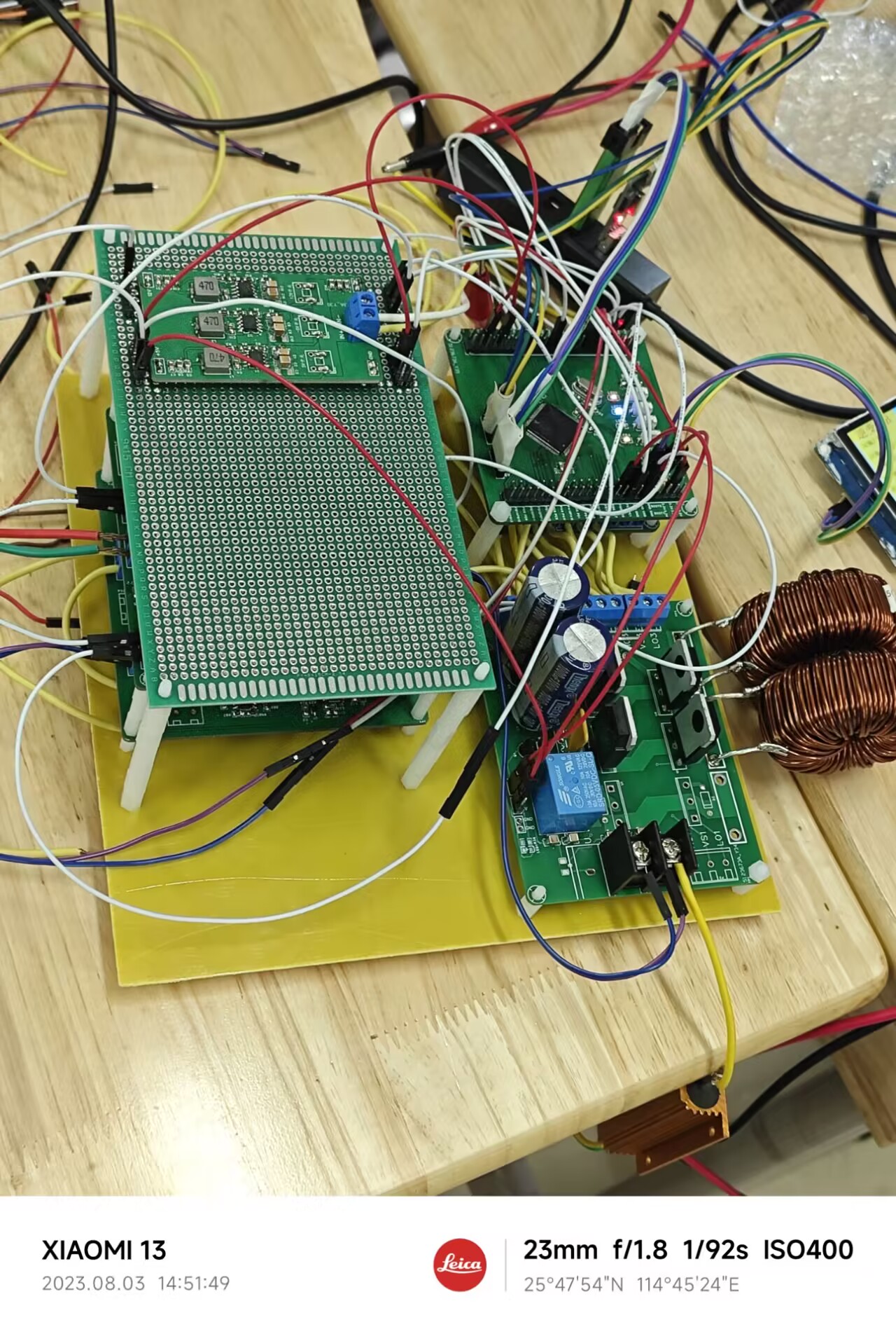
This work is based on the SPWM wave inverter principle. Through monitoring and control circuits, when a DC power supply is input, the circuit performs DC-AC conversion. The main circuit structure of this work is an H-bridge structure composed of IR2104S driven by the SPWM wave and IGBTs, which is used to realize the detection circuit structure for controlling the output voltage. The inverter circuit as a whole is powered by a DC power supply, which in turn powers an auxiliary power supply, which in turn powers the microcontroller, driver chip, and detection circuit. The first part reduces THD by adjusting the SPWM wave carrier frequency and the LC filter circuit.
The second part samples the AC voltage through a voltage transformer, amplifies it through an operational amplifier circuit, and inputs it to a microcontroller via an adder. The data is then processed, the modulation ratio is changed, and the output voltage is stabilized, reducing the load regulation rate.
Keywords: SPWM inverter, H-bridge, STM32, voltage transformer, modulation ratio, IR2104S
Table of Contents
I. Scheme Demonstration 3
II. Theoretical Analysis and Calculation 3
III. Circuit and Program Design 3
IV. Test Scheme and Test Results 3
Single-Phase Inverter Parallel Operation System (Problem A)
I. Scheme Demonstration
1.1 Structure Selection
Scheme 1: Single-Phase Inverter Half-Bridge Topology The
half-bridge inverter circuit structure is simple and low-cost, but its disadvantages include half the output voltage and the output current being limited by the capacitor, resulting in low inverter output power and low efficiency.
Scheme 2: Single-Phase Inverter Full-Bridge Topology
The single-phase inverter H-bridge topology uses a parallel topology of two half-bridges. This scheme allows for program-controlled output voltage, high degree of freedom, and significantly higher inverter efficiency than the half-bridge structure. Its disadvantages are a more complex circuit structure and more complex control.
Because the full-bridge topology allows for voltage control and offers high efficiency, this group selected Scheme 2.
1.2 Main Control Chip Selection
: The STM32F407 series microcontroller is used. STM32 is a 32-bit microcontroller manufactured by STMicroelectronics. The STM32 series offers fast processing speed, low power consumption, rich peripheral interfaces, abundant library function development resources, and a higher clock speed and faster processing speed compared to the F103 series, while also being compatible with hardware floating-point units. This group decided to use the STM32F407VET6 microcontroller, which is reasonably priced and powerful.
1.3 Power Transistor Selection:
This system uses the IBGT (FGA25N120), packaged in TO-220, with a forward current of 25A, reverse withstand voltage of 1200V, and an operating temperature of -55~155℃, suitable for high-power applications.
1.4 Scheme Description:
SPWM is a commonly used inverter modulation technique that controls the amplitude and frequency of the inverter output voltage by controlling the switching time of the inverter switches. Advantages of SPWM technology: It can generate an output voltage that approximates a sine wave, and the voltage change rate between two half cycles is small, with fewer current harmonic components and simple control. 1.5. Demonstration and Selection of SPWM Wave Inverter Circuit
Scheme 1: H4IP4081 Four-way Complementary Driver + Full-bridge Inverter Circuit The
HIP4081 is a medium-frequency, medium-voltage, full-bridge configuration. The H-bridge is a driver IC with four N-channel MOSFETs, which is suitable for medium-power applications.
Scheme 2: IR2104S Four-way Complementary Driver + Full-bridge Inverter Circuit
The IR2104S is a high-voltage, high-speed power MOSFET and IGBT driver. The related high and low reference voltage output channels can simultaneously output a set of complementary PWM wave circuits to achieve inversion.
Combining the above two schemes, Scheme 2 is selected.
1.6 Demonstration and Selection of Control System
Since two sets of inverters need to be connected in parallel and connected to the grid, it is necessary to process the inverter output voltage and the grid voltage to be of the same frequency and voltage.
Option 1: Hardware Phase-Locked Loop (PLL) + Partial Software Closed-Loop Processing.
The hardware samples the grid voltage, inverter output voltage, and current. The hardware performs zero-crossing comparison and peak detection on the sampled signals, and inputs the processed signals to the microcontroller to obtain the phase and amplitude relationship. The microcontroller processes the data and modifies the SPWM for closed-loop control.
Option 2: Full Software Closed-Loop Processing .
The hardware circuit samples the grid voltage, inverter output voltage, and current, performs amplification and addition circuits, and acquires waveform signals. The microcontroller processes the data, modifies the SPWM, and performs closed-loop control.
Option Selection:
Because the microcontroller needs to drive the IGBTs quickly, the rapid switching of the switching transistors will cause rapid changes in voltage and current, which may lead to two zero-crossings in the hardware PLL, or multiple rising edges in a 50Hz square wave signal within one cycle. In Option 2, the microcontroller acquires the voltage after the addition circuit. If the switching transistors cause spike pulses, the microcontroller can process the glitches. After consideration, this group chose Option 2.
II. Theoretical Analysis and Calculation
2.1 Output Circuit
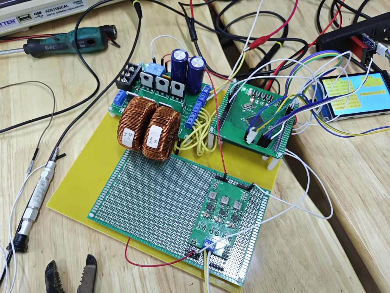
The output circuit uses a full-bridge inverter controlled by four IGBTs, followed by LC circuit filtering. The four IGBTs are driven by two IR2104S filters, enabling rapid switching, easy adjustment, and more precise waveform control using SPWM. Since a 50Hz sine wave is required, a low-pass filter needs to be designed. An LC filter is used, with the cutoff frequency calculated as f = 1 / 2π√LC. We decided to use a 500uH inductor (L) and a parallel connection of a 22uF and a 10uF capacitor (C). The calculated cutoff frequency is 1258Hz, resulting in a sine wave with low distortion.
III.
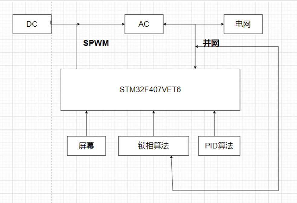
3.1 System Overall Block Diagram Figure

1 System Overall Block Diagram
3.2 Inverter Topology
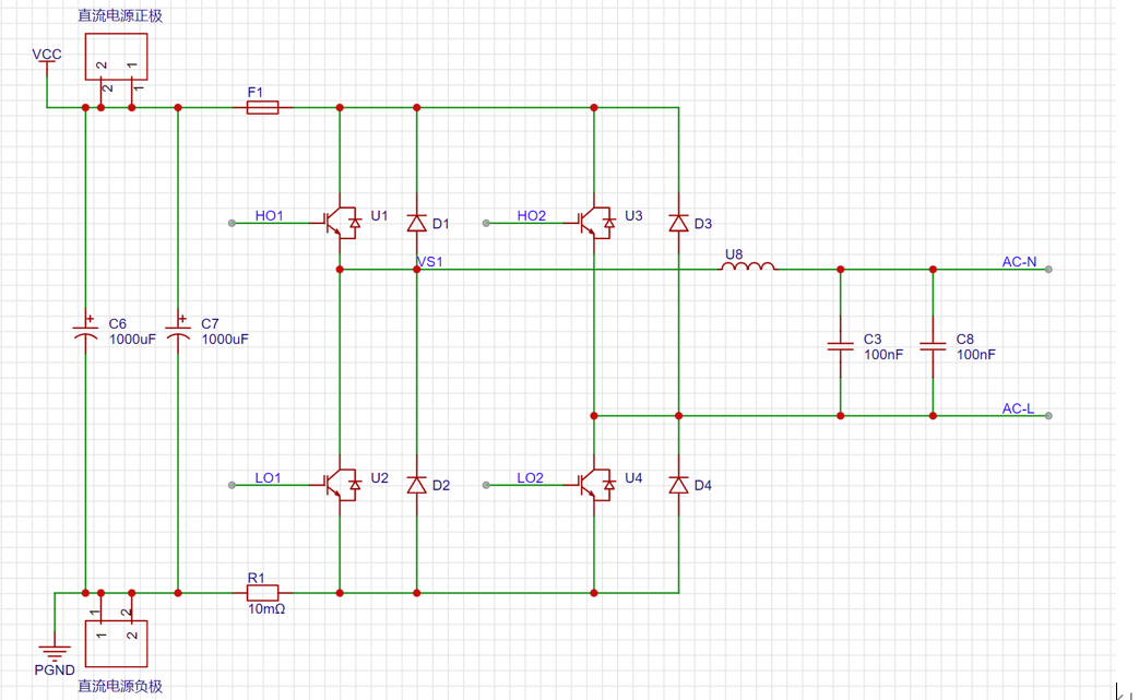
Figure 2 Inverter Topology Circuit Diagram
3.4 Detection Circuit The AC
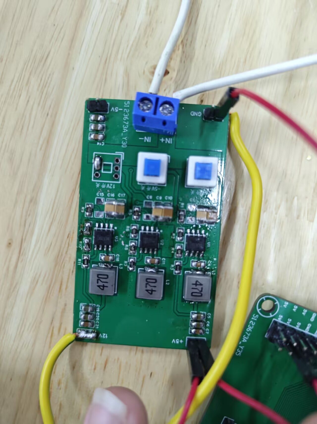
voltage sampling circuit uses a ZMPT101B to sense the voltage, and the AC current uses a ZMCT103C to sense the AC current. The signals are input to the microcontroller via an arithmetic circuit and an adder circuit. The bias voltage signal is provided by a REF3318, providing a constant 1.8V DC signal. The operational amplifier is a TLC2272 low-noise operational amplifier. The microcontroller collects the data, subtracts the DC bias, and multiplies by the amplification factor to obtain the effective value of the AC voltage. The DC voltage is acquired using a resistor divider, and the input is fed to the microcontroller in the same direction. The DC current is detected using a low-side differential amplifier circuit.
3.5 Program Design
The core software uses the output of the SPWM to control the switching transistors to realize a full-bridge inverter. SPWM (Sinusoidal Pulse Width Modulation) is a mature and widely used technology. It is based on the principle of area equivalence, meaning that narrow pulses with equal impulse but different shapes applied to an inertial element produce essentially the same effect.<sup>1</sup> SPWM inversion is a mature technology; both unipolar and bipolar inversion rely on SPWM modulation. For H-bridge full-bridge inversion, bipolar SPWM inversion is used.<sup>2</sup> The microcontroller can output PWM via TIM. In the program, a sine table can be generated by calculating ARR and modulation ratio, and then the SPWM can be implemented by looking up the table. PWM events are used to trigger interrupts and update the next CCR value.
Secondly, screen information interaction is implemented on the controller MCU, enabling real-time response to screen input and output operations. This means that on-screen information interaction can receive rapid feedback after user input, providing a better user experience. The screen UI and its information interaction keys are designed through serial port screen host computer software, and some parameters are displayed or set through communication with the microcontroller via serial port.
To control the stability of the inverter voltage, the software collects instantaneous values of DC input voltage, current signal, inverter voltage, current, and grid voltage signal, calculates effective values, and performs coordinated open-loop and closed-loop control to achieve inverter voltage stability and closed-loop control.
IV. Test Scheme and Test Results
4.1 Test Scheme and Test Conditions
① Connect the power analyzer's current measurement line in series with the circuit, and the voltage range in parallel. Connect the load in series with the circuit and measure whether the output voltage reaches 24V and the output current reaches 2A. Observe whether the distortion rate meets the requirements.
② Adjust the load so that the current continuously varies from 0 to 2A, and measure whether the load rate is within SI1≤0.2%.
③ Connect the power analyzer to the circuit, turn on inverter 1, supply power to the load, stabilize it at 24V, turn on inverter 2, observe whether the load voltage is at 24V, and observe whether it can output 4A current.
4.2 Test Results and Completeness
① Connect the load to the circuit. It can output 24V±0.2V AC, and the current can reach 2A. The voltage distortion rate is within 2%.
② Adjust the load so that the current changes continuously from 0 to 2A, detect the change in voltage, and perform calculations. It can be seen that the load rate SI1 is within 0.2%.
The file ele_game_power_supply_407VET6_V5.zip is a file containing the code.
serialplot.zip is a software for viewing waveforms.


 This project is based on https://oshwhub.com/sytnocui/star-pcb-drawing and reference tutorials at https://www.bilibili.com/video/BV18H4y1L7UY


 京公网安备 11010802033920号

 M55342K12B10F2TWA


