 LED pin initialization and KEY pin initialization are relatively basic and will not be discussed in detail. Of particular note are the `Key_GetState()` and `Key_GetNum()` functions in `Key.c`. `Key_GetState()` returns the key value corresponding to each key pressed. For example, if key 1 is detected as pressed (GPIO PB13 pin is low), the key state is returned as the return value. In `Key_GetNum()`, the previous and current key states are read. If a key is always pressed, the current key state will never be zero, and the function returns the previous value of `keynum`. Only when a key is released does the function begin to determine which key was previously pressed based on the previous state. For example, if the current key state is 0 and the previous key state was 1, then KEY1 can be considered pressed, and the key value of KEY1 is returned.
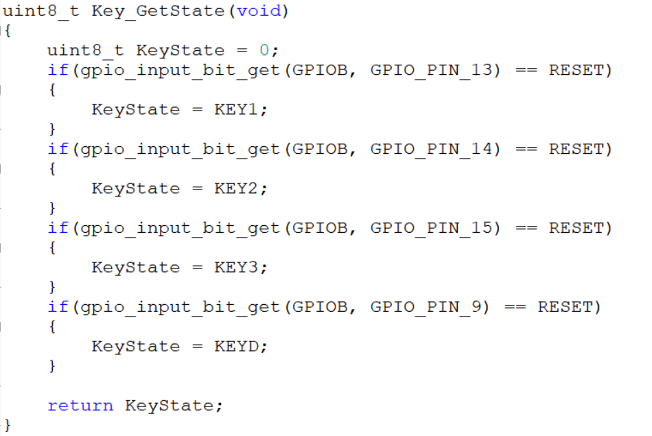

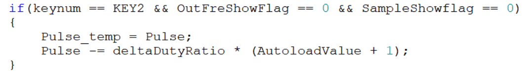
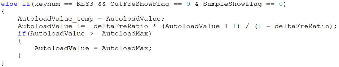
 Serial port initialization and external interrupt initialization are also quite basic and will not be discussed in detail. It's worth noting the external interrupt function 4-15 (void EXTI4_15_IRQHandler(void)) in main.c. This function adjusts the PWM output frequency, duty cycle, and ADC sampling time of the GD32 chip based on the current key value and the rotation state of the rotary encoder. Within the function, the variables cnt1 and cnt2 store the clockwise (counterclockwise) rotation of the rotary encoder, primarily to prevent misjudgments.
 Optional values can be found in the gd32e23x_adc.c file by pressing Ctrl+F in the project, entering ADC_SAMPLETIME_239POINT5 in Find what, looking in the Current Project dropdown, and clicking Find Next at the bottom of the window. The optional values can be found in the gd32e23x_adc.c file.
 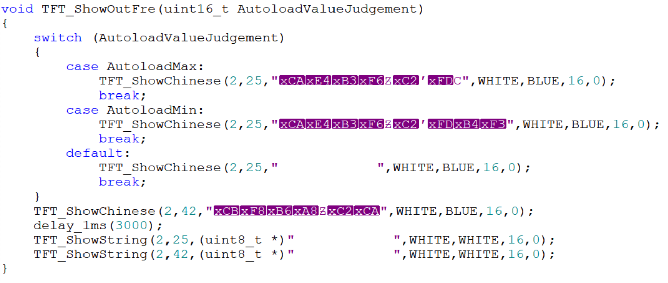 The garbled characters are due to initially using GB32 encoding, which was later changed back to UTF-8. Therefore, it's crucial to develop good coding habits and maintain consistent encoding formats. The same applies to sampling time; changing the sampling time will trigger a prompt, and the sampling time can only be changed after the prompt ends. The Key_ControlPWM() function adds the functionality to display changes on the screen when the sampling time changes. The last two lines are spaces used to refresh the screen and display the sampling time prompt.
All reference designs on this site are sourced from major semiconductor manufacturers or collected online for learning and research. The copyright belongs to the semiconductor manufacturer or the original author. If you believe that the reference design of this site infringes upon your relevant rights and interests, please send us a rights notice. As a neutral platform service provider, we will take measures to delete the relevant content in accordance with relevant laws after receiving the relevant notice from the rights holder. Please send relevant notifications to email: bbs_service@eeworld.com.cn.
It is your responsibility to test the circuit yourself and determine its suitability for you. EEWorld will not be liable for direct, indirect, special, incidental, consequential or punitive damages arising from any cause or anything connected to any reference design used.
Supported by EEWorld Datasheet
EEWorld
subscription
account

EEWorld
service
account

Automotive
development
community

Robot
development
community

About Us Customer Service Contact Information Datasheet Sitemap LatestNews


Room 1530, 15th Floor, Building B,
No.18 Zhongguancun Street,
Haidian District,
Beijing, Postal Code: 100190
China
Telephone: 008610 8235 0740
 京公网安备 11010802033920号

 MV1N5225CTR


