Features:
Dual-channel design, enabling simultaneous sampling
. Utilizes two independent ADCS7476AIMF/NOPB ADC chips, with a maximum sampling rate of 1Msps.
ESP32s2 is the main controller
. Onboard antenna allows for future PC integration via Wi-Fi.
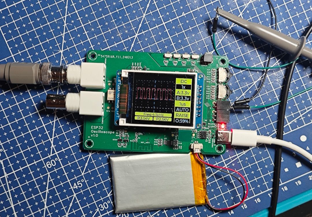
Includes an onboard 3.7V lithium battery charging and power module, charging via Type-C and independently powered by battery.
Onboard CH340X serial port chip allows direct programming via Type-C .
Output ports: PWM*1, I2C*1, or GPIO*3 for future expansion.
Electronic switches for AC/DC coupling and 1x/5x switching.
Features 4x tactile switches and 2x rotary encoder switches, currently used for adjusting PWM output duty cycle and frequency, as well as coupling mode and range switching; more functions can be added later.
Implementation Principle:
Electronic switches replace the physical DIP switches used in the training camp case for
coupling mode and range switching. The training camp used physical DIP switches. Physical switches are not elegant enough, and their proximity to the oscilloscope probe interface significantly limits their placement and hinders enclosure design. Therefore, electronic switches were used instead. Since
the voltage of the oscilloscope probe is not constant and can potentially generate negative voltage, a signal relay was used as the electronic switch. An NMOS transistor controls the relay's switching.
A single SPI bus is used to simultaneously sample two independent ADC chips.
The SPI's two-wire data mode (DIO) can be used directly, with both MISO and MOSI lines used for reading. Each data line corresponds to one ADC chip for simultaneous reading. However, when reading data using this setting, the received data will be alternating bit-by-bit between chips a and b:
The received data is 32 bits like "ababababababababababab", but it needs to be split into two 16-bit data segments, "aaaaaaaa" and "bbbbbbbb" . To avoid processing bit-by-bit using a for loop (which seems too slow), two LUT lookup tables are used to
directly retrieve the data (see the source code for details). The oscilloscope uses the two encoder switches on the right side: the upper one adjusts the PWM output duty cycle, and the lower one adjusts the PWM output frequency. The four tactile switches above are for switching coupling mode and 1x/5x speed from left to right; the remaining buttons are currently unused and reserved for future upgrades. This oscilloscope project software uses ESP32. Written using the IDF framework, it can be directly compiled and programmed using IDF. The interface is drawn using LVGL. A problem encountered during the process was that the program ran normally after being programmed on the PC, but failed to run after unplugging the USB cable and restarting the machine. This was mainly due to unfamiliarity with the CH340X chip. The #DTR signal controlling the switching between download mode and normal mode was different from the example in the chip's datasheet. The example was for STM32, and the BOOT pin polarity was reversed compared to ESP32, causing the default boot mode to fail to start normally. This issue has been fixed in the latest project. The ADC chip malfunction was caused by a problem with the chip's datasheet. The datasheet mentioned that the SPI transmission protocol sends bits one by one according to the LSB order, but the voltage parsed according to this order was completely random due to the reversed bit order, initially leading to the assumption of a chip malfunction. After repeated troubleshooting and almost giving up, the possibility of a bit order issue was considered. Rereading and decoding according to the MSB order restored everything to normal. The power switch frequently causes screen flickering during power-on and power-off. The power switch uses a self-locking switch, and the signal switches between on and off multiple times during the switching process. This switch controls the battery output through a PMOS transistor. The gate of this PMOS transistor is directly connected to the self-locking switch. Forgetting to add a capacitor caused unstable power supply during switching. This issue has been fixed in the latest version.


 京公网安备 11010802033920号

 THD12-4823


