Preface:
I've always wanted to create a reward and punishment game-themed ambient light. It would be usable as both a game and an ambient light.
When awake, it could be used for interactive games for adults or for playing with kids. The game content could be customized via a panel—any reward or punishment would be possible, haha.
At night, it could be colorful, a breathing light, or simply create a specific atmosphere… Basically, it's always on 24/7. Haha, just thinking about it sounds fun!
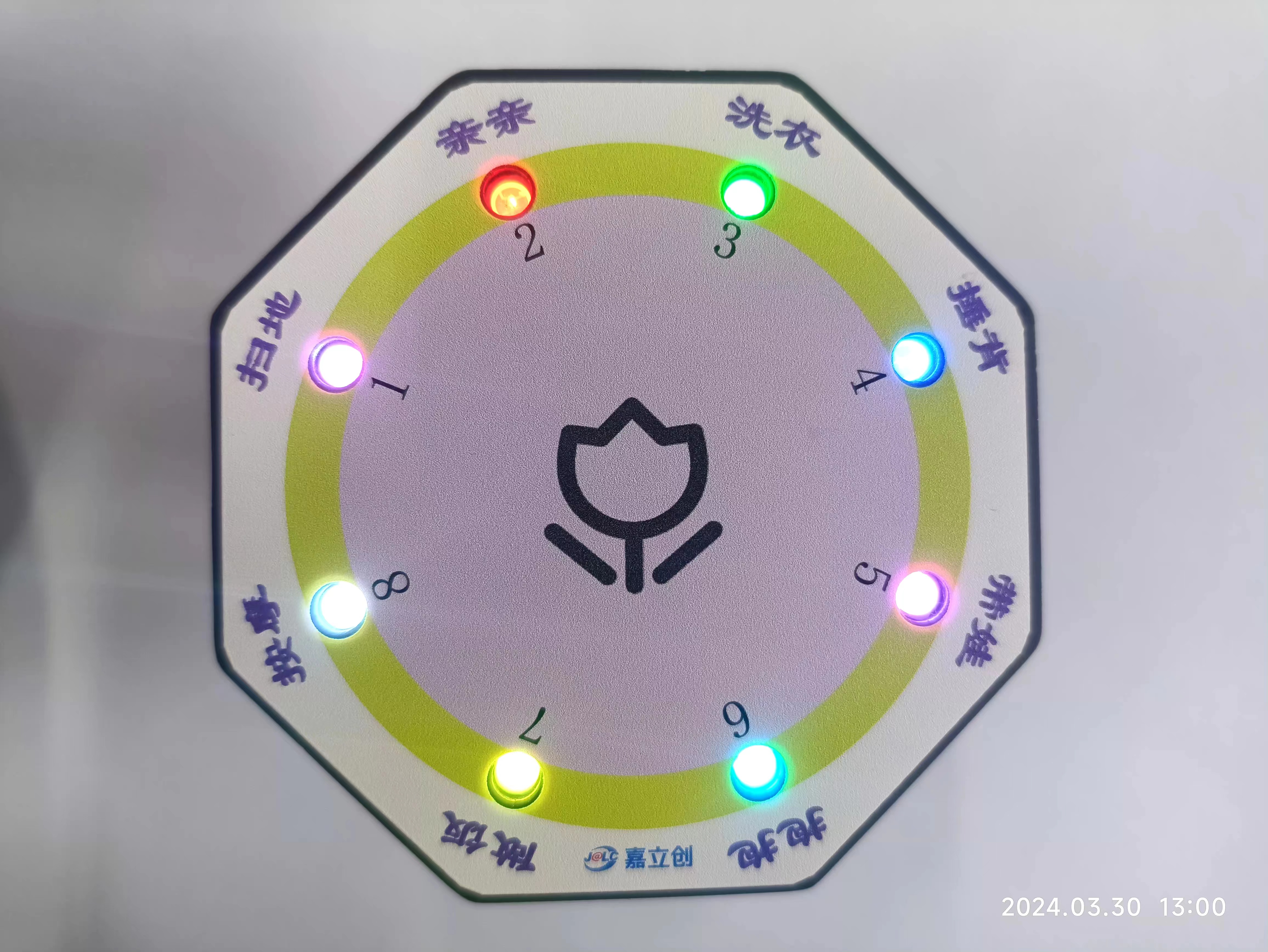
Here it is, with customizable rewards and punishments.
Voice Control Function


Note: Sometimes the voice reception isn't very sensitive, possibly due to my non-standard Mandarin. Fewer voice commands are better; otherwise, the more commands, the slower the response and the less sensitive the response.
Hardware Design :
Designed using LCSC EDA.
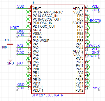
The main control unit
uses the STM32F103. Why choose this one? It has sufficient functionality and abundant resources. See
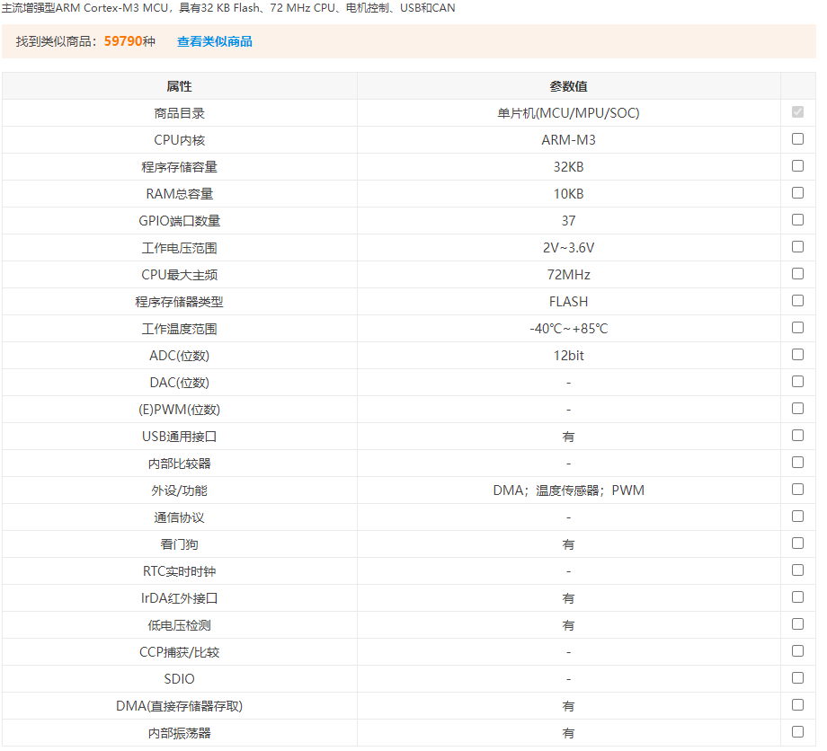
the design below:
Main functions:
1- Control the voice module;
2- Control the LED display effect;
3- Implement a random algorithm;
4- Implement power detection;
5- Parse voice commands.
The WS2812 display
circuit
uses eight WS2812 chips. Because they can be connected in series, only one IO is needed to control the display effect and color changes, saving a lot of MCU IO resources compared to LEDs.
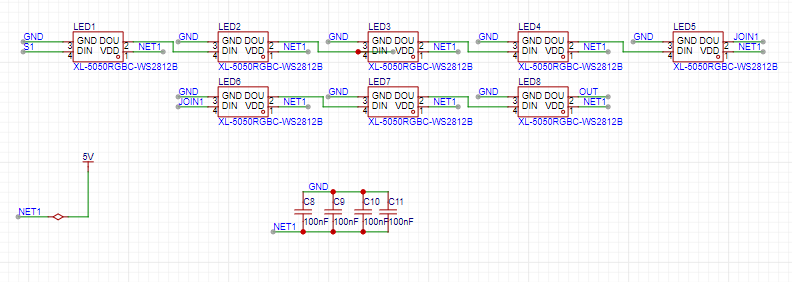
Note: The power supply voltage should not be less than 3.5V; the higher the brightness, the higher the power consumption.
The WS2812 introduction
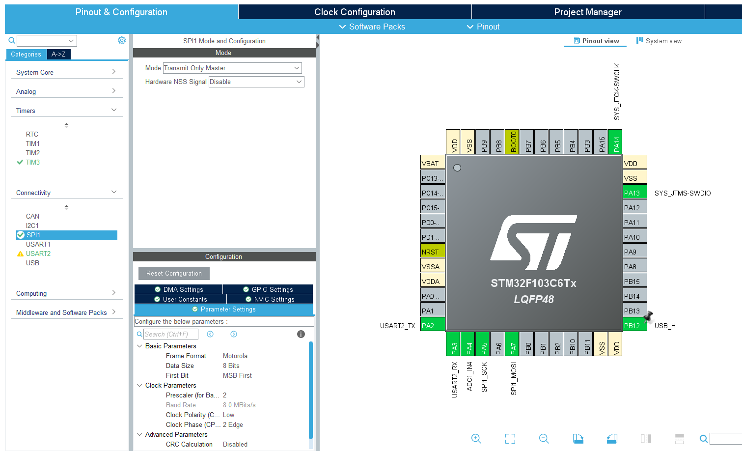
uses four WS2812B chips. Color control is achieved through the PA7 pin, using SPI+DMA. PA7 is a MOSI pin, which can be set to transmit-only mode, saving pins.
The WS2812 chip uses single-wire communication and sends signals using a return-to-zero code. After power-on reset, the chip receives data from DIN. After receiving 24 bits, the DOUT pin starts forwarding data, providing input data for the next chip. Before forwarding, the DOUT port remains low, during which time the chip does not accept new data. The chip's three PWM output ports, OUTR, OUTG, and OUTB, emit signals with different duty cycles based on the received 24-bit data, with a period of 4ms. If the input signal at the DIN terminal is a RESET signal, the chip will send the received data to the display. The chip will then accept new data again after this signal ends. After receiving the initial 24 bits of data, it forwards the data through the DOUT port. Before receiving a RESET signal, the original outputs of OUTR, OUTG, and OUTB remain low. When a low-level RESET code of more than 80µs is received, the chip will receive the 24-bit PWM data pulse width and output it to OUTR, OUTG, and OUTB.
Detailed parameters are as follows:
Power input voltage: 3.5-7.5V
; OUT R/G/B constant current value: 12mA;
Top SMD internally integrates high-quality external control single-wire serial cascaded constant current IC
control circuit. The control circuit and chip are integrated into the SMD 5050 component, forming a complete externally controlled pixel. The color temperature effect is uniform and consistent.
Built-in data shaping circuit: after any pixel receives a signal, it is shaped before output, ensuring that the waveform distortion is not increased. The
default power-on light is not lit.
Gray scale adjustment circuit (256 levels of gray scale adjustable).
Data shaping: after receiving the data of this unit, it automatically shapes and outputs the subsequent data.
Built-in high-precision and high-stability oscillator
single-wire data transmission, which can be infinitely cascaded.
High data protocol compatibility
. Data transmission rate: 800Kbps.
Voice module
HLK-V20 schematic diagram
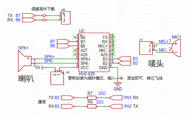
receives data through serial port, default 115200 baud rate.
Note: The label must be of good quality, otherwise it will be very insensitive. A slightly inferior speaker is okay, as long as it makes a sound.
The label must be of good quality!
Choose the right label!
Choose the right label!
HLK-V20
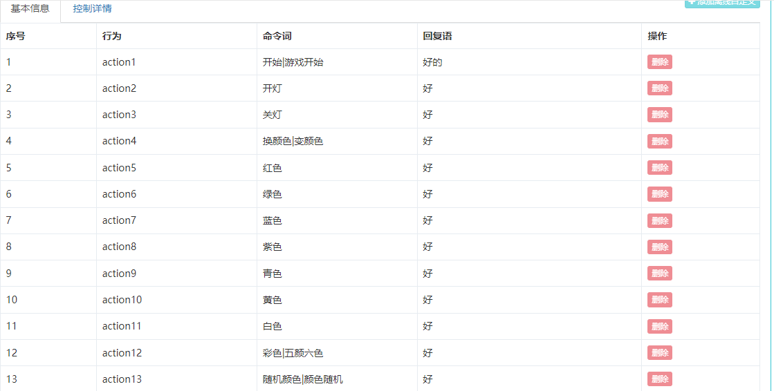
requires customized voice control commands.
My control commands are as follows:

Each module needs to download the customized voice commands first. For specific customization methods, please refer to the Liangshanpai Module Porting Manual.
My customization details are in the attachment; you can download and use them directly.
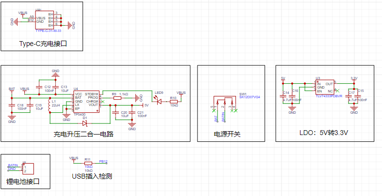
Power Supply
Design:
1- Charging via Type-C
; 2- Charging and boosting to 5V via TP5400. Why boost? Because the WS2812 power supply must be above 3.6V.
3- The LDO uses a TLV74333 to 3.3V converter because the MCU power supply cannot exceed 3.6V.
4- USB insertion detection: input is present when pin PB12 is high.
5- Lithium battery directly connected via 2.54mm header pins.
6- SW1 switch controls whether the lithium battery is powered.
TP5400
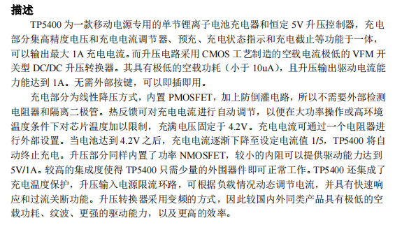
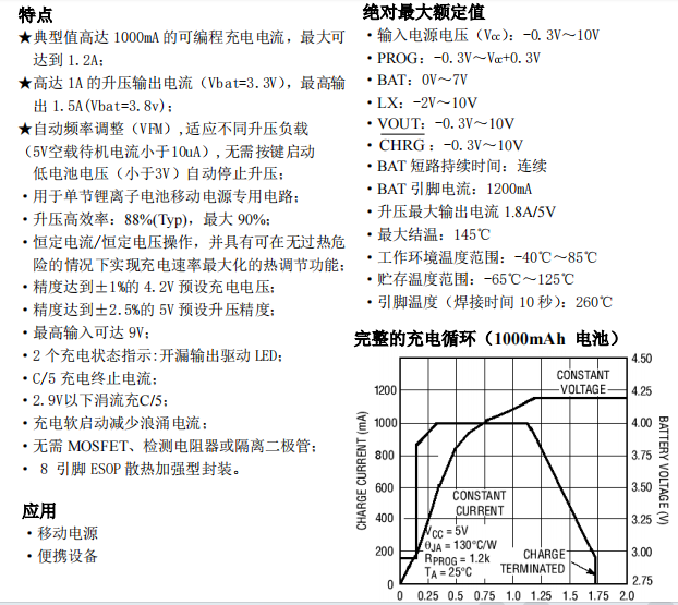
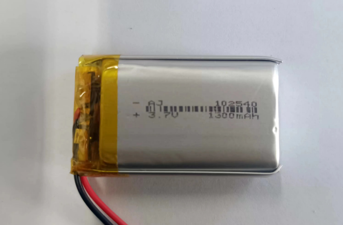
lithium battery specifications
need to be purchased from Taobao, 1300mAh, as follows:
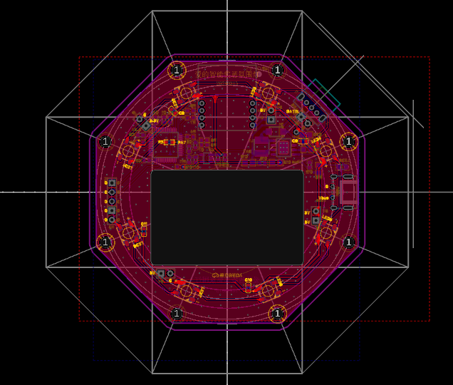
PCB Design:
Designed using LCSC EDA. Double-layer board, 1.6mm, FR-4 board material. The 76x76mm
3D shell design
was done using LCSC EDA.

Bottom cover:

Top cover:

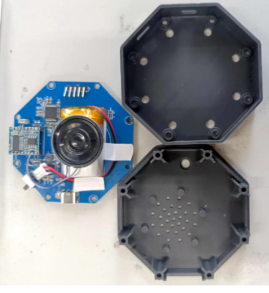
Actual product image .
Panel design
was also done using LCSC EDA . Actual
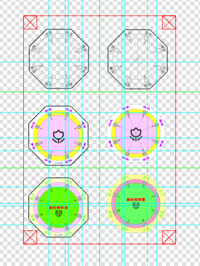
product shown below:

The program design and
development tools and environment
used a combination of CubeMX and Keil5, developed using C language.
CubeMX configuration is as follows:
Design concept
1- Power sampling, data acquisition via ADC.
2- Voice module data reception .
3- Command analysis.
4- Display effect algorithm implementation
. Detailed information on the HLK-V20 module is available in the Liangshanpai module development.
My customized voice module is detailed in the attachment. The driver code is mostly
for common peripherals, serial port implementation, etc., and will not be discussed in detail. Various effects in the main program are implemented here; the specific code is as follows: / USER CODE BEGIN Header / /**
@file : main.c
@brief : Main program body
@attention
Copyright (c) 2024 STMicroelectronics.
All rights reserved.
This software is licensed under terms that can be found in the LICENSE file
in the root directory of this software component.
If no LICENSE file comes with this software, it is provided AS-IS.
/
/ USER CODE END Header /
/ Includes ------------------------------------------------------------------*/
include "main.h"
include "adc.h"
include "spi.h"
include "tim.h"
include "usart.h"
include "gpio.h"
/ Private includes ---------------------------------------------------------------/
/ USER CODE BEGIN Includes /
include "RGB_SPI.h"
include "stdlib.h"
/ USER CODE END Includes /
/ Private typedef ---------------------------------------------------------------/
/ USER CODE BEGIN PTD /
/ USER CODE END PTD /
/ Private define ---------------------------------------------------------------/
/ USER CODE BEGIN PD /
/ USER CODE END PD /
/ Private macro --------------------------------------------------------/
/ USER CODE BEGIN PM /
/ USER CODE END PM /
/ Private variables ---------------------------------------------------------/
/ USER CODE BEGIN PV /
volatile uint32_t cnt=1;
volatile RGB_InitStruce Set_Color;
volatile uint8_t Flag_Game=0;
volatile uint8_t Num_Color=0;
volatile uint8_t Num_100ms=0;
volatile uint8_t myBrightness=6;
volatile uint16_t adc_value=0;
/ USER CODE END PV /
/ Private function prototypes --------------------------------------------------/
void SystemClock_Config(void);
/ USER CODE BEGIN PFP /
void Roll(void);
/ USER CODE END PFP /
/ Private user code ---------------------------------------------------------------/
/ USER CODE BEGIN 0 //
USER CODE END 0 /
/**
@brief The application entry point.
@retval int
/
int main(void)
{
/ USER CODE BEGIN 1 */
/ USER CODE END 1 /
/ MCU Configuration----------------------------------------------------------------/
/ Reset of all peripherals, Initializes the Flash interface and the Systick./
HAL_Init();
/ USER CODE BEGIN Init /
/ USER CODE END Init /
/ Configure the system clock /
SystemClock_Config();
/ USER CODE BEGIN SysInit /
/ USER CODE END SysInit /
/ Initialize all configured peripherals /
MX_GPIO_Init();
MX_USART2_UART_Init();
MX_SPI1_Init();
MX_ADC1_Init();
MX_TIM3_Init();
/ USER CODE BEGIN 2 /
HAL_TIM_Base_Start_IT(&htim3);
Set_Color=WHITE;
Num_Color=1;
/ USER CODE END 2 /
/ Infinite loop / /
USER CODE BEGIN WHILE /
while (1)
{
/ USER CODE END WHILE /
/ USER CODE BEGIN 3 /
HAL_ADC_Start(&hadc1);
if(USART_RX_STA&0x8000)
{
uint16_t len=USART_RX_STA&0x3fff;//Get the length of the data received this time
USART_RX_STA=0;
if(len==1)
{
Flag_Game=0;
switch(USART_RX_BUF[0]){
case 'y'://Game switch
Flag_Game=1;
Num_100ms=0;
break;
case 'k'://Turn on the light
Num_Color=1;//White
//Set_Color=WHITE;
break;
case 'g'://Turn off the light
Num_Color=0;
//Set_Color=BLACK;
break;
case 'h'://Change color
Num_Color++;
if(Num_Color>9) Num_Color=1;
break;
case 'W'://white
Num_Color=1;
break;
case 'R'://red
Num_Color=2;
break;
case 'G'://green
Num_Color=3;
break;
case 'B'://blue
Num_Color=4;
break;
case 'Y'://yellow
Num_Color=5;
break;
case 'V'://violet
Num_Color=6;
break;
case 'C'://cyan
Num_Color=7;
break;
case 'F'://colorful
Num_Color=8;
break;
case 'S'://Random color
Num_Color=9;
break;
case 'M'://Maximum brightness
myBrightness=20;
break;
case 'm'://Minimum brightness
myBrightness++;
if(myBrightness>20) myBrightness=20;
break;
case '+'://Increase brightness
Num_Color=7;
break;
case '-'://Decrease brightness
myBrightness--;
if(myBrightness<1) myBrightness=1;
break;
case 'z'://Moderate brightness
myBrightness=5;
break;
default:break;
}
}
// HAL_UART_Transmit(&huart2,USART_RX_BUF,len,10); //Send received data
// while(__HAL_UART_GET_FLAG(&huart2,UART_FLAG_TC)!=SET); // Wait for the sending to finish
}
if(Flag_Game==1)
{
srand(uwTick);
Num_100ms++;
if(Num_100ms<=20)
{
Roll();
}else{
Num_100ms=0;
for (uint8_t i = 0 ; i < RGB_NUM ; i++ )
{
RGB_Set_Buf(i,BLACK);
}
RGB\_Set\_Buf(rand()%8,VIOLET);
RGB\_Send\_Handler(RGB\_NUM);
Flag\_Game=2;
}
}
if(Flag\_Game==0){
switch(Num\_Color){
case 1://turn on the light
//white
Set\_Color=WHITE;
break;
case 0://turn off the light
Set\_Color=BLACK;
break;
case 2://red
Set\_Color=RED;
break;
case 3://green
Set\_Color=GREEN;
break;
case 4://blue
Set\_Color=BLUE;
break;
case 5://yellow
Set\_Color=YELLOW;
break;
case 6://violet
Set\_Color=VIOLET; break;
case
7://cyan Set
\ _Color=CYAN; RGB\_Set\_Buf(cnt%8,WHITE); RGB\_Set\_Buf((cnt+1)%8,VIOLET); RGB\_Set\_Buf((cnt+2)%8,RED); RGB\_Set\_Buf((cnt+3)%8,GREEN); RGB\_Set\_Buf((cnt+4)%8,BLUE); RGB\_Set\_Buf((cnt+5)%8,VIOLET); RGB\_Set\_Buf((cnt+6)%8,CYAN); RGB\_Set\_Buf((cnt+7)%8,YELLOW); if(Num\_100ms==50) { Num\_100ms=0; RGB\_Send\_Handler(RGB\_NUM); } break; case 9://random color if((cnt%10)==0) { RGB\_InitStruce temp\_color; srand(uwTick); for (uint8\_t i = 0 ; i < RGB\_NUM ; i++ ) { temp\_color.R=rand()%10; temp\_color.G=rand()%10; temp\_color.B=rand()%10; RGB\_Set\_Buf(i,temp\_color); } RGB\_Send\_Handler(RGB\_NUM); } break;
default:break;
}
if(Num\_Color<8){
for (uint8\_t i = 0 ; i < 8 ; i++ )
{
RGB\_Set\_Buf(i,Set\_Color);
}
RGB\_Send\_Handler(RGB\_NUM);
}
}
if(HAL\_OK==HAL\_ADC\_PollForConversion(&hadc1,10))
{
adc\_value=HAL\_ADC\_GetValue(&hadc1);
if(adc\_value<2066)
{
for (uint8\_t i = 0 ; i < RGB\_NUM ; i++ )
{
RGB\_Set\_Buf(i,BLACK);
}
RGB\_Set\_Buf(0,RED);
RGB\_Send\_Handler(RGB\_NUM);
}
}
HAL\_SuspendTick();
HAL\_PWR\_EnterSLEEPMode(0,PWR\_SLEEPENTRY\_WFI);
HAL\_ResumeTick();
}
/ USER CODE END 3 /
}
/**
@brief System Clock Configuration
@retval None
*/
void SystemClock_Config(void)
{
RCC_OscInitTypeDef RCC_OscInitStruct = {0};
RCC_ClkInitTypeDef RCC_ClkInitStruct = {0};
RCC_PeriphCLKInitTypeDef PeriphClkInit = {0};
/** Initializes the RCC Oscillators according to the specified parameters
in the RCC_OscInitTypeDef structure.
*/
RCC_OscInitStruct.OscillatorType = RCC_OSCILLATORTYPE_HSI;
RCC_OscInitStruct.HSIState = RCC_HSI_ON;
RCC_OscInitStruct.HSICalibrationValue = RCC_HSICALIBRATION_DEFAULT;
RCC_OscInitStruct.PLL.PLLState = RCC_PLL_ON;
RCC_OscInitStruct.PLL.PLLSource = RCC_PLLSOURCE_HSI_DIV2;
RCC_OscInitStruct.PLL.PLLMUL = RCC_PLL_MUL4;
if (HAL_RCC_OscConfig(&RCC_OscInitStruct) != HAL_OK)
{
Error_Handler();
}
/* Initializes the CPU, AHB and APB buses clocks
/
RCC_ClkInitStruct.ClockType = RCC_CLOCKTYPE_HCLK|RCC_CLOCKTYPE_SYSCLK
|RCC_CLOCKTYPE_PCLK1|RCC_CLOCKTYPE_PCLK2;
RCC_ClkInitStruct.SYSCLKSource = RCC_SYSCLKSOURCE_PLLCLK;
RCC_ClkInitStruct.AHBCLKDivider = RCC_SYSCLK_DIV1;
RCC_ClkInitStruct.APB1CLKDivider = RCC_HCLK_DIV2;
RCC_ClkInitStruct.APB2CLKDivider = RCC_HCLK_DIV1;
if (HAL_RCC_ClockConfig(&RCC_ClkInitStruct, FLASH_LATENCY_0) != HAL_OK)
{
Error_Handler();
}
PeriphClkInit.PeriphClockSelection = RCC_PERIPHCLK_ADC;
PeriphClkInit.AdcClockSelection = RCC_ADCPCLK2_DIV2;
if (HAL_RCCEx_PeriphCLKConfig(&PeriphClkInit) != HAL_OK)
{
Error_Handler();
}
}
/ USER CODE BEGIN 4 /
void HAL_TIM_PeriodElapsedCallback(TIM_HandleTypeDef *htim)
{
if(htim->Instance==TIM3)
{
cnt++;
}
}
void Roll(void)
{
uint8_t jsq=(cnt%8);
for (uint8_t i = 0 ; i < 8 ; i++ )
{
RGB_Set_Buf(i,BLACK);
}
switch(jsq)
{
case 0:
RGB_Set_Buf(jsq,RED);RGB_Send_Handler(RGB_NUM);
break;
case 1:
RGB_Set_Buf(jsq,GREEN);RGB_Send_Handler(RGB_NUM);
break;
case 2:
RGB_Set_Buf(jsq,BLUE);RGB_Send_Handler(RGB_NUM);
break;
case 3:
RGB_Set_Buf(jsq,WHITE);RGB_Send_Handler(RGB_NUM);
break;
case 4:
RGB_Set_Buf(jsq,CYAN);RGB_Send_Handler(RGB_NUM);
break;
case 5:
RGB_Set_Buf(jsq,VIOLET);RGB_Send_Handler(RGB_NUM);
break;
case 6:
RGB_Set_Buf(jsq,YELLOW);RGB_Send_Handler(RGB_NUM);
break;
case 7:
RGB_Set_Buf(jsq,CYAN);RGB_Send_Handler(RGB_NUM);
break;
default:break;
}
}
/ USER CODE END 4 /
/**
@brief This function is executed in case of error occurrence.
@retval None
/
void Error_Handler(void)
{
/ USER CODE BEGIN Error_Handler_Debug /
/ User can add his own implementation to report The HAL error returns state /
__disable_irq();
while (1)
{
}
/ USER CODE END Error_Handler_Debug */
}
ifdef USE_FULL_ASSERT
/**
@brief Reports the name of the source file and the source line number
where the assert_param error has occurred.
@param file: pointer to the source file name
@param line: assert_param error line source number
@retval None
/
void assert_failed(uint8_t file, uint32_t line)
{
/ USER CODE BEGIN 6
// User can add his own implementation to report the file name and line number,
ex: printf("Wrong parameters value: file %s on line %d
", file, line) //
USER CODE END 6 /
}endif / USE_FULL_ASSERT /
The attached code can be used directly.
For a demonstration,
due to file size limitations, you can open the following link to view the effect.
https://www.bilibili.com/video/BV1Gm411C7Bj/?vd_source=24f1befd6441a33d7b240715cb07c7b5


 京公网安备 11010802033920号

 ELM410


