Introduction Link: https://www.bilibili.com/video/BV1wf421f7qL/?vd_source=0932b066ad5079c0e33d7684bbc536be
1. Product Introduction:
A brushed ESC for RC model applications. Key features include: compact size, high power, and high linearity at low speeds.
2. Application Scenarios:
2-3S power supply RC car brushed motor drive, or other brushed motors that meet 2-3S voltage requirements and, with heat dissipation, can achieve a continuous current of 10A and a peak current of up to 30A.
3. Product Overview:
This project mainly designs brushed motors for RC models, especially small-scale cars and drift cars where ESC size is critical. Unlike the integrated H-bridge drive used in ordinary brushed ESCs, this project benefits from a discrete high-performance H-bridge gate-level drive and compact MOS packaging design. The driver board achieves a certain continuous power output capability with high low-speed linearity and stable output while maintaining a small size. It also features built-in low-voltage battery protection, driver board temperature monitoring, and start-up point adjustment.
4. Product Parameters:
Size: 16mm x 22mm x 8mm, meeting the space requirements of small-scale mosquito car models
. Main Controller: STM32G030F6P6, 64MHz.
Power Supply: 2-3S polymer lithium battery.
BEC: 5V 3A BEC power supply capability
. Drive Capability: 4A continuously without heat dissipation, 10A continuously with heat dissipation, peak 30A.
Programming Interface: SWD.
Production Cost: Approximately 10-15 RMB.
PCB Parameters: 16X22mm, four-layer board, components on both sides.
Functional Modes: Forward/Reverse/Brake, two operating modes: normal mode and single-pedal mode.
5. Instructions for Use:
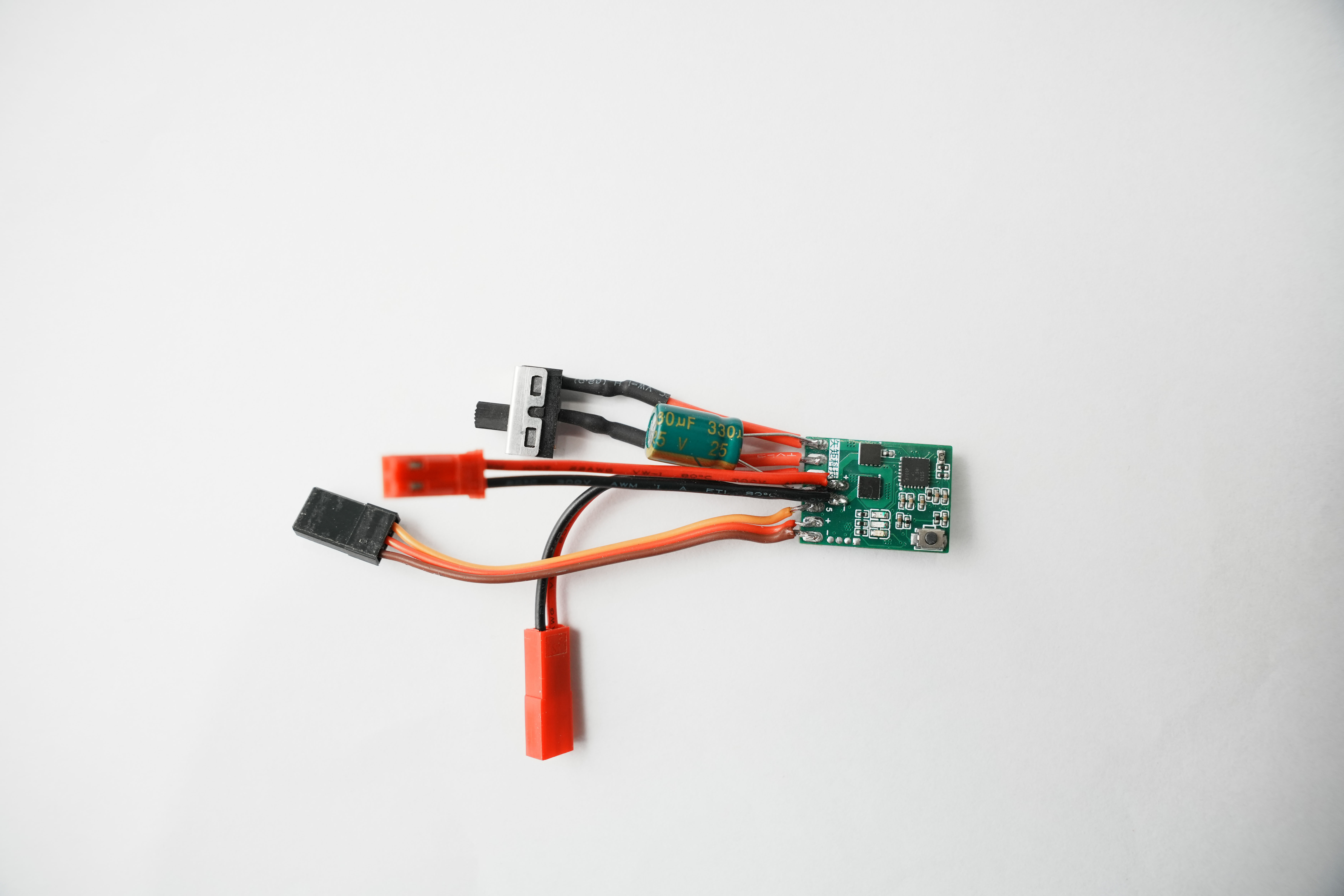
In addition to the finished PCB, you will need to prepare corresponding connectors (JST male/female connectors shown in the diagram), a receiver 3P connector, a 33uf 25V electrolytic capacitor, and a switch (SS12D10 straight-leg switch shown in the diagram) according to the battery and motor connectors.

Solder the wires as shown in the diagram below. For the electrolytic capacitor (note the difference between positive and negative pins), solder the negative pin to the negative power supply pin and the positive pin to the left-side switch pin.
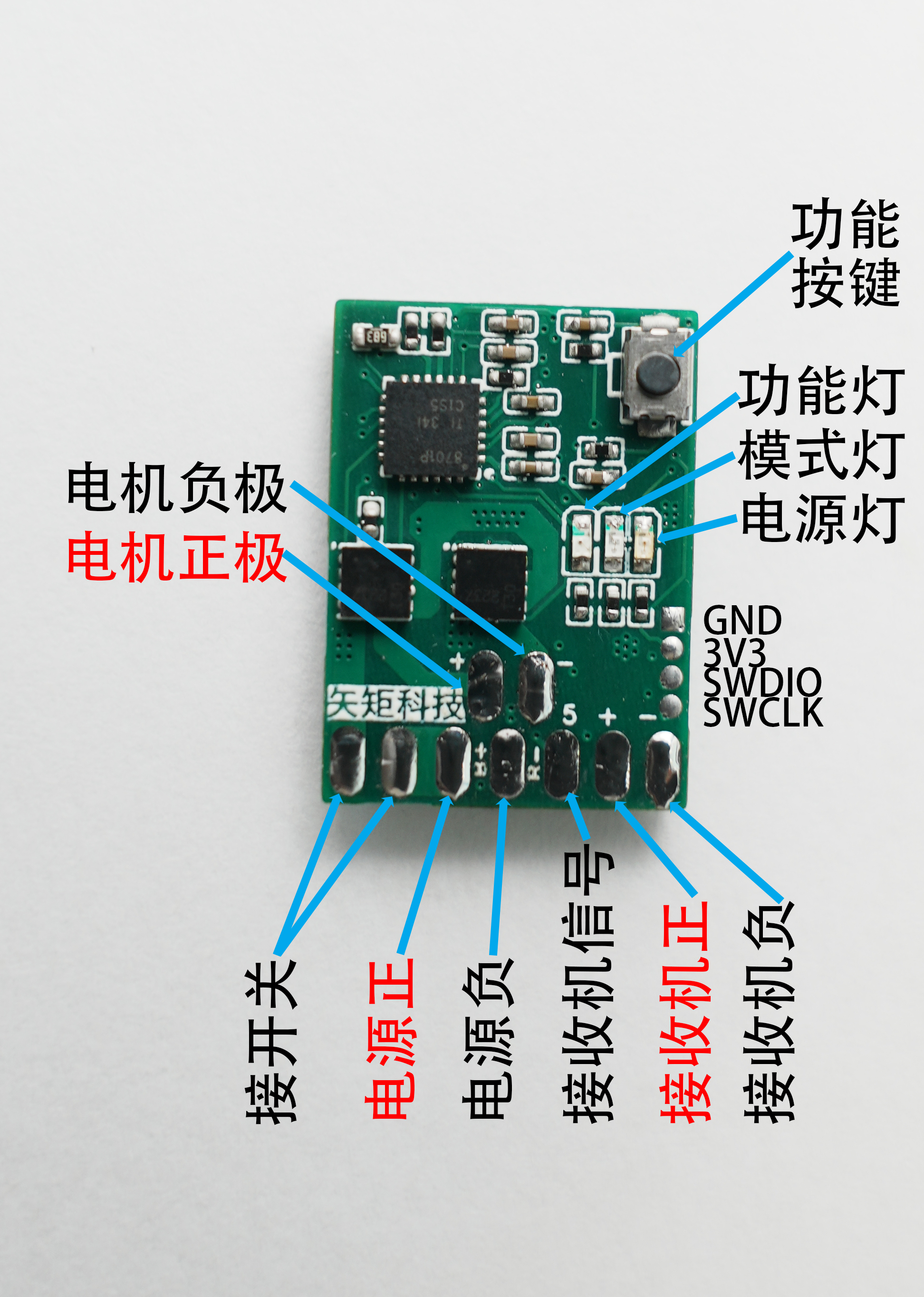
The finished product should look like the image below .
The function buttons have the following functions:
A short press switches between two operating modes, and the function light flashes once;
a short press sets the battery to 2 seconds, and the function light flashes twice;
a short press sets the battery to 3 seconds, and the function light flashes three times;
a short press followed by four flashes of the function light, then a power outage and restart restores all default settings;
a long press for 2-4 seconds and release sets the throttle start point, and the function light flashes five times;
a long press for more than 5 seconds until the function light starts to illuminate, then release and the function light flashes six times, setting the throttle midpoint.
All function settings are saved after a power outage and only need to be set once.
Explanation of the two operating modes:
Normal mode: This is the default operating mode. The mode light indicates that it is in normal mode. It can move forward, backward, and brake. When moving forward, pushing the accelerator to the reverse position initiates braking; when moving backward, pushing the accelerator to the forward position initiates braking. While braking, returning the accelerator to the center and pushing it once in the opposite direction resumes forward/backward movement. It's important to note that unlike regular proportional braking, the braking ratio of this drive pedal is variable. A larger accelerator pedal position results in a higher braking ratio, and a smaller accelerator pedal position results in a lower braking ratio.
One-pedal mode: The mode light is off, indicating that it is in one-pedal mode. The term "one-pedal mode" is derived from electric vehicle terminology; pushing the accelerator forward initiates forward movement, the accelerator at the center position initiates braking, and pushing the accelerator backward initiates reverse movement. The braking ratio is fixed at 50%.
Explanation of throttle activation point:
Under normal circumstances, the ESC uses a full-proportional throttle design; the amount of throttle applied corresponds to the amount of power. However, when starting a vehicle, there is a process of power overcoming static friction resistance. In other words, before the accelerator reaches a certain level, the power is insufficient to move the vehicle. The purpose of setting the throttle start point is to minimize the ineffective throttle travel (in actual testing, the ineffective throttle travel of a certain mosquito-shaped vehicle is approximately 45%), ensuring the vehicle moves immediately upon pressing the throttle. Reducing the ineffective throttle also increases the effective linear throttle range, resulting in more precise control.
The method for setting the throttle start point is as follows: It is recommended to set the throttle midpoint first. After setting, slowly push the throttle until the wheels start to move, then release the throttle by about 5%, hold the position, and then press and hold the function button for 2-4 seconds before releasing. Five flashes of the function light indicate successful setting. Then slowly push the throttle and see if the wheels start to turn slowly when the throttle is low; if so, it is effective. If the setting fails, restore the default settings and repeat the above steps until successful.
After connecting all wires and powering on, the power light will remain constantly on. It is recommended to set the throttle midpoint and start point after powering on.
The drive board has a temperature sensor. When the drive temperature exceeds 80 degrees, the drive will shut down and the function light will
flash rapidly. It has a low voltage protection function. After setting the number of battery strings, when the voltage of a single battery string is lower than 3.35V, the drive will shut down and the function light will flash slowly.
6. Remarks:
(1) If the switch function is not needed, simply short-circuit the two pins of the switch. If the motor continuous current is greater than 5A, it is recommended to choose a switch with a higher current.
(2) The recommended capacity of the electrolytic capacitor is 330uf. The actual capacity should be selected according to the motor specifications.
(3) The battery is set to 2S in the initial state. If a 3S battery is used, it will enter the low voltage protection state and the function light will flash slowly continuously. After powering on, the motor will not turn when the throttle is pushed.
(4) If the wheel is turning when the throttle is in the center position after powering on in the initial state, setting the throttle to the center position will solve the problem; (
5) The source code is not open source. The firmware is provided in the attachment. The firmware burning interface is a 1.27mm pitch pad. You can use a 1.27mm pitch burning probe or flying wire to burn the program through STM32CubeProgrammer. For specific usage methods, please search on Baidu;
(6) It is best to use heat shrink tubing to prevent short circuits with other parts;
(7) The NTC resistor must be 10kB with a value of 3950, otherwise the temperature judgment will be inaccurate and the machine will not run;
(8) For motors used in small scale 1/24 or 1/28 mosquito car cars, there is no problem in using them directly without adding heat dissipation; For high-power motors with a continuous current of more than 4A, a heat sink needs to be added to the MOSFET. It is recommended to use a 10x14mm long and wide heat sink to attach to the MOSFET. You can use the 3D printed parts in the attachment to install it as shown in the figure below. After adding the heat sink, it can output 10A continuously.

Firmware V1.0.rar
For heat dissipation, this casing can be printed. (zip file)
PDF_RC Model Applications: Mini High Linearity Brushed ESC.zip
Altium_RC Model Applications: Mini High Linearity Brushed ESC.zip
PADS_RC Model Applications: Mini High Linearity Brushed ESC.zip
Mini high-linearity brushed ESCs used in BOM_RC model.xlsx
95554
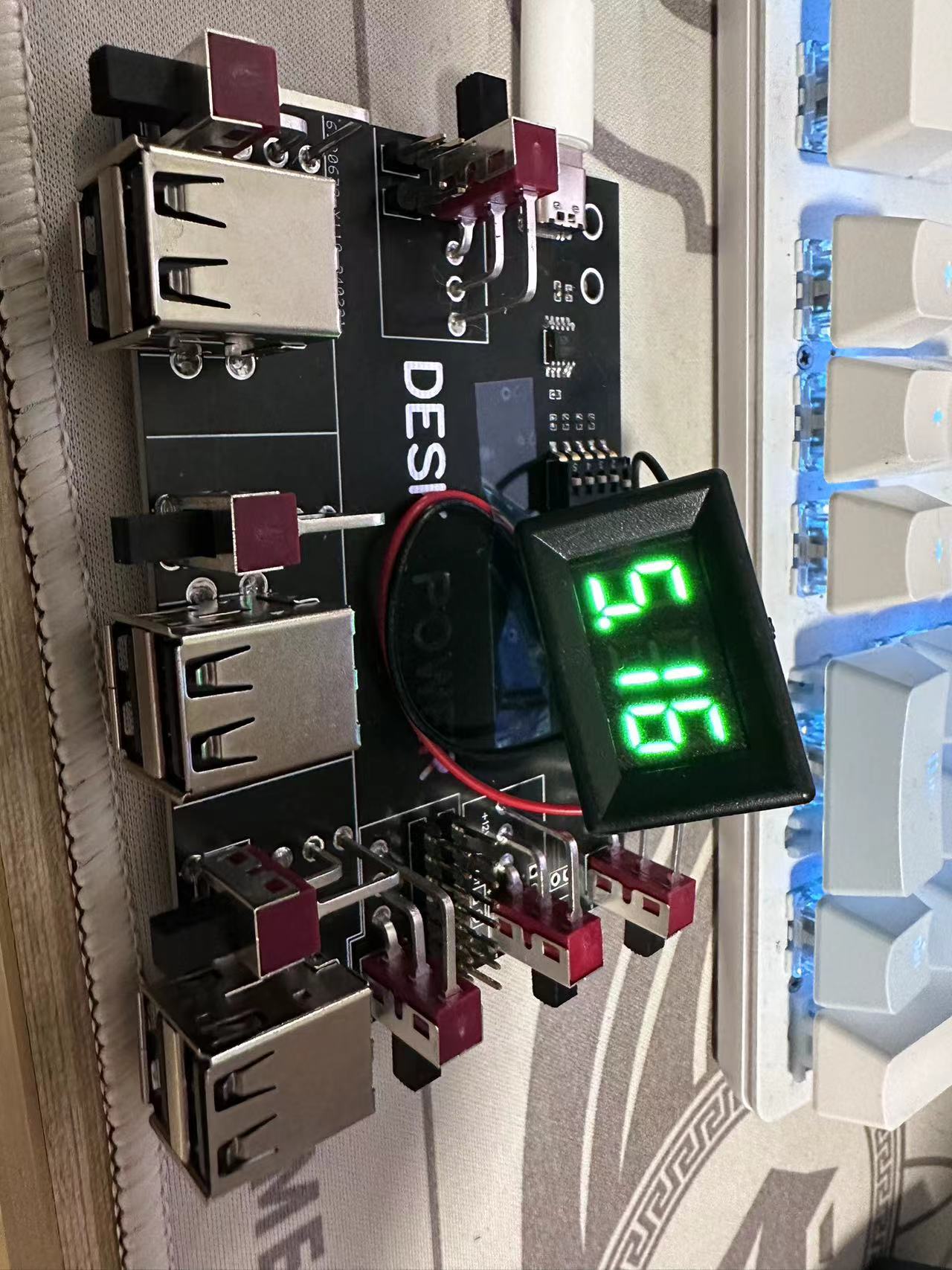
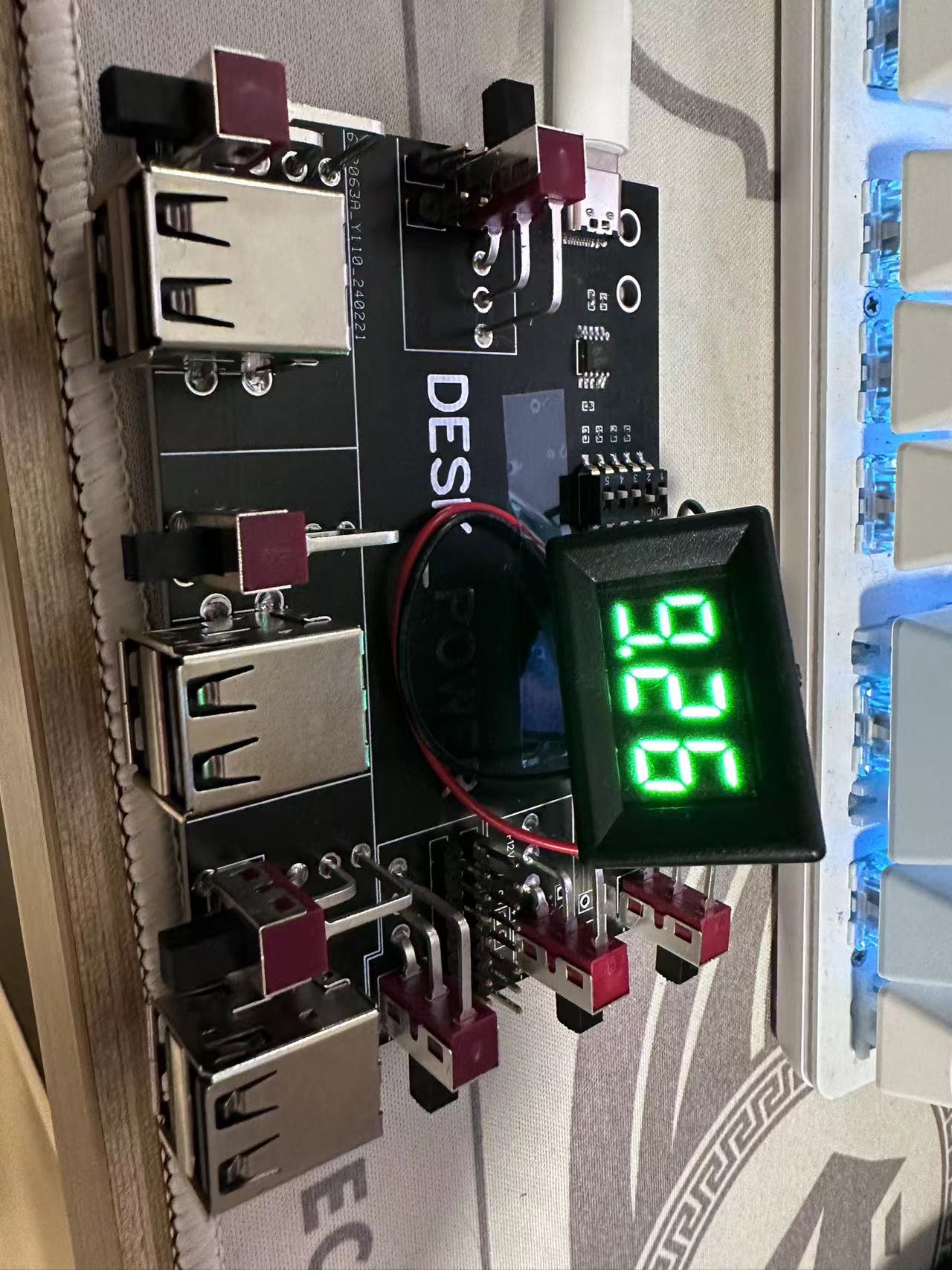
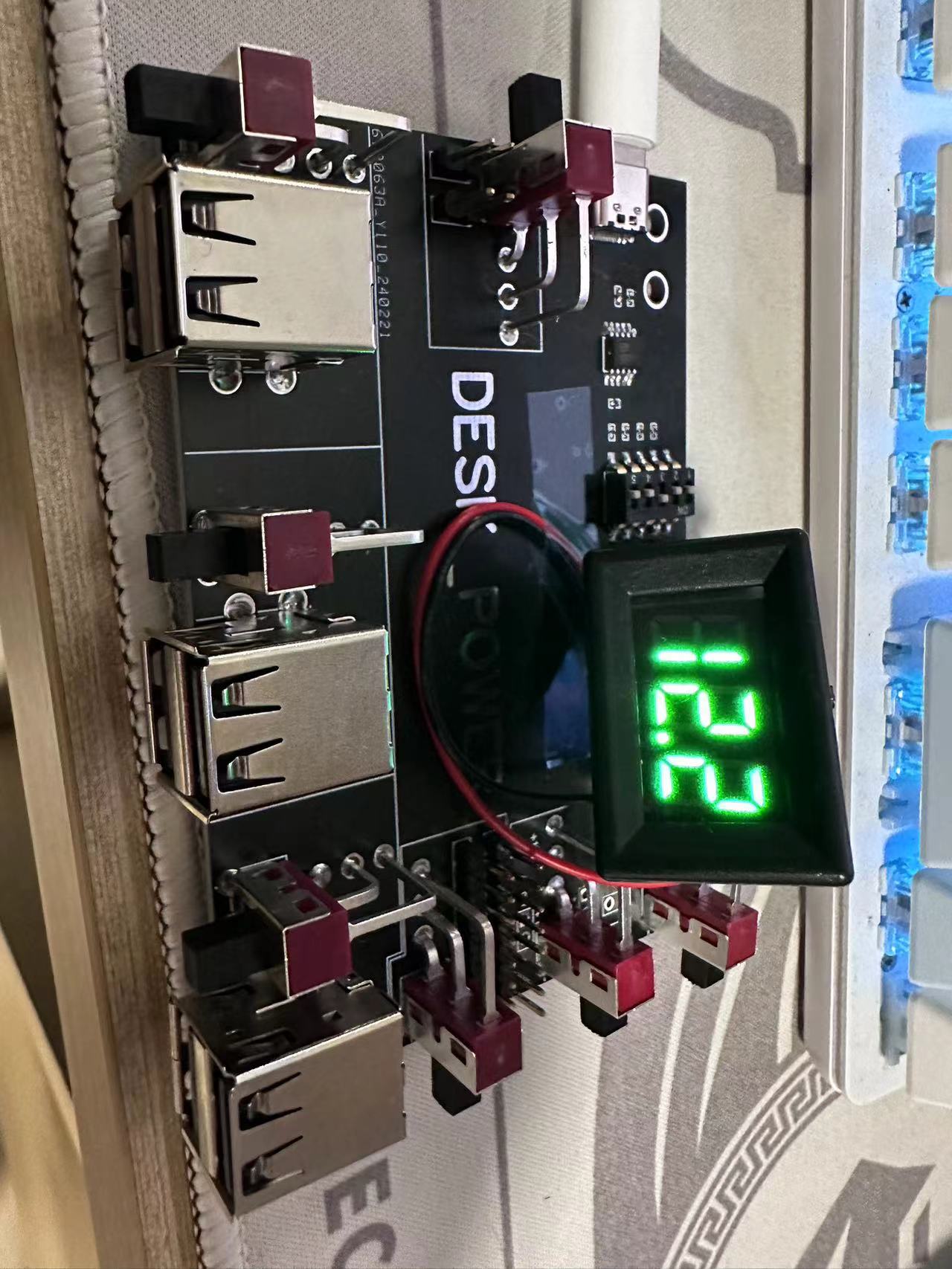
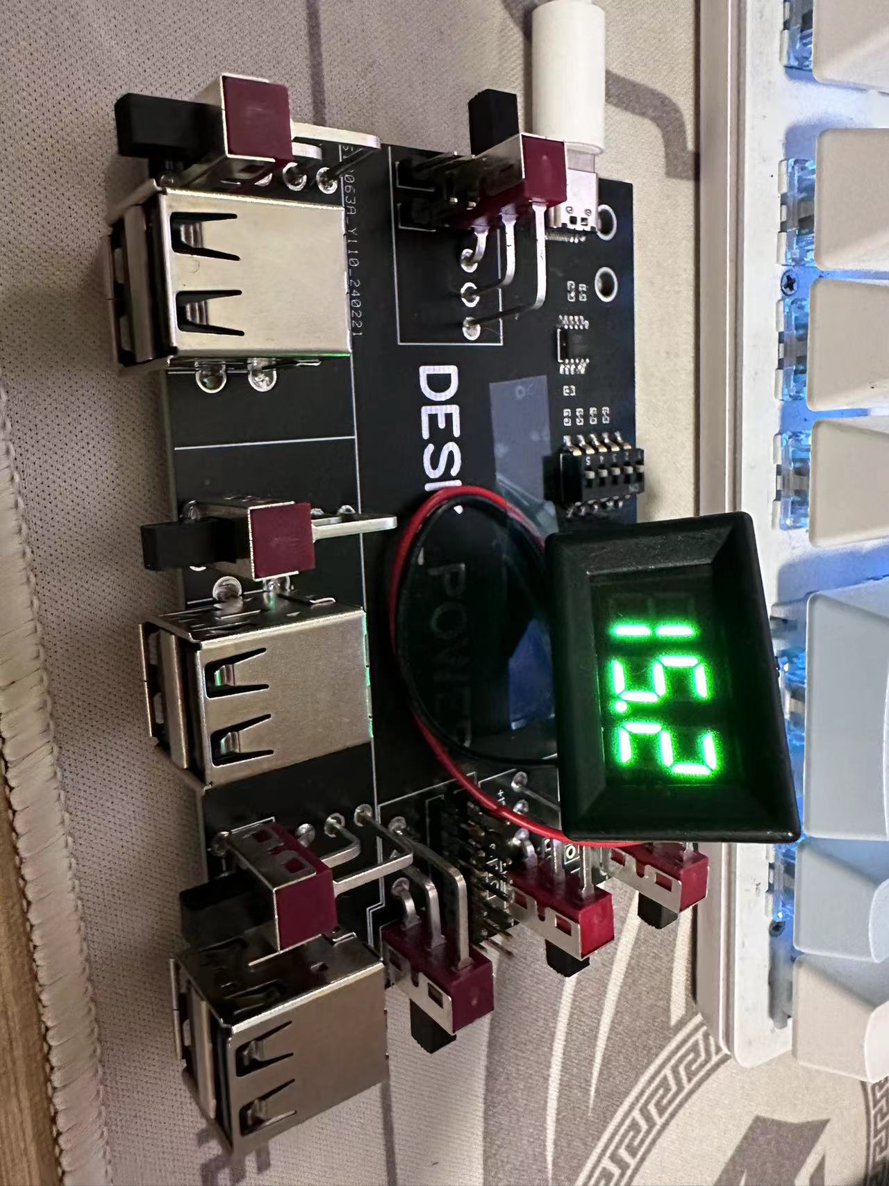
PD desktop power supply with random voltage output (for children's entertainment)
Each port on the board outputs a voltage randomly, ranging from 0 to 15V. The probability of not burning out the USB port is as high as one in four! Surely no one would keep switching between phones until the very last one before it burns out!
10d7abc918f293f4ceed0f08338459f9.mp4
PDF_PD Desktop Power Supply with Random Voltage Output (Entertainment Version).zip
Altium_Random Voltage Output PD Desktop Power Supply (Foolproof Version).zip
PADS_Random Voltage Output PD Desktop Power Supply (Foolproof Version).zip
BOM_PD Desktop Power Supply with Random Voltage Output (Enthusiast Version).xlsx
95555
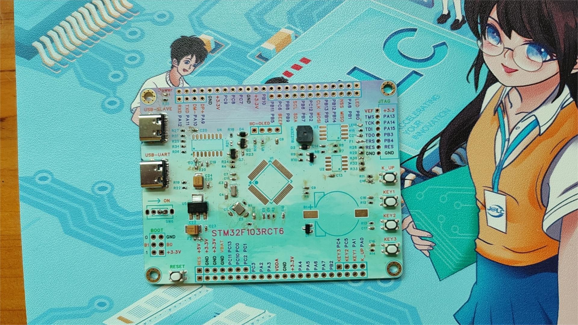
STM32F103RCT6 Simple Core Board
A simple core board based on STM32F103RCT6
A simple core board based on the STM32F103CRT6. The development board includes peripherals such as I2C, SPI, OLED, buttons, and a buzzer. These peripherals are connected to the microcontroller pins via jumper caps, allowing for easy connection to other pins using jumper wires. This makes it ideal for STM32 microcontroller development, effectively avoiding fixed peripheral pins and peripheral conflicts.
Notes:
1. Modified on March 26, 2024.
2. This project is not fully verified; only some peripherals have been verified and some issues have been fixed. Please carefully check the schematic design before printing.
3. Unauthorized commercial use is prohibited.
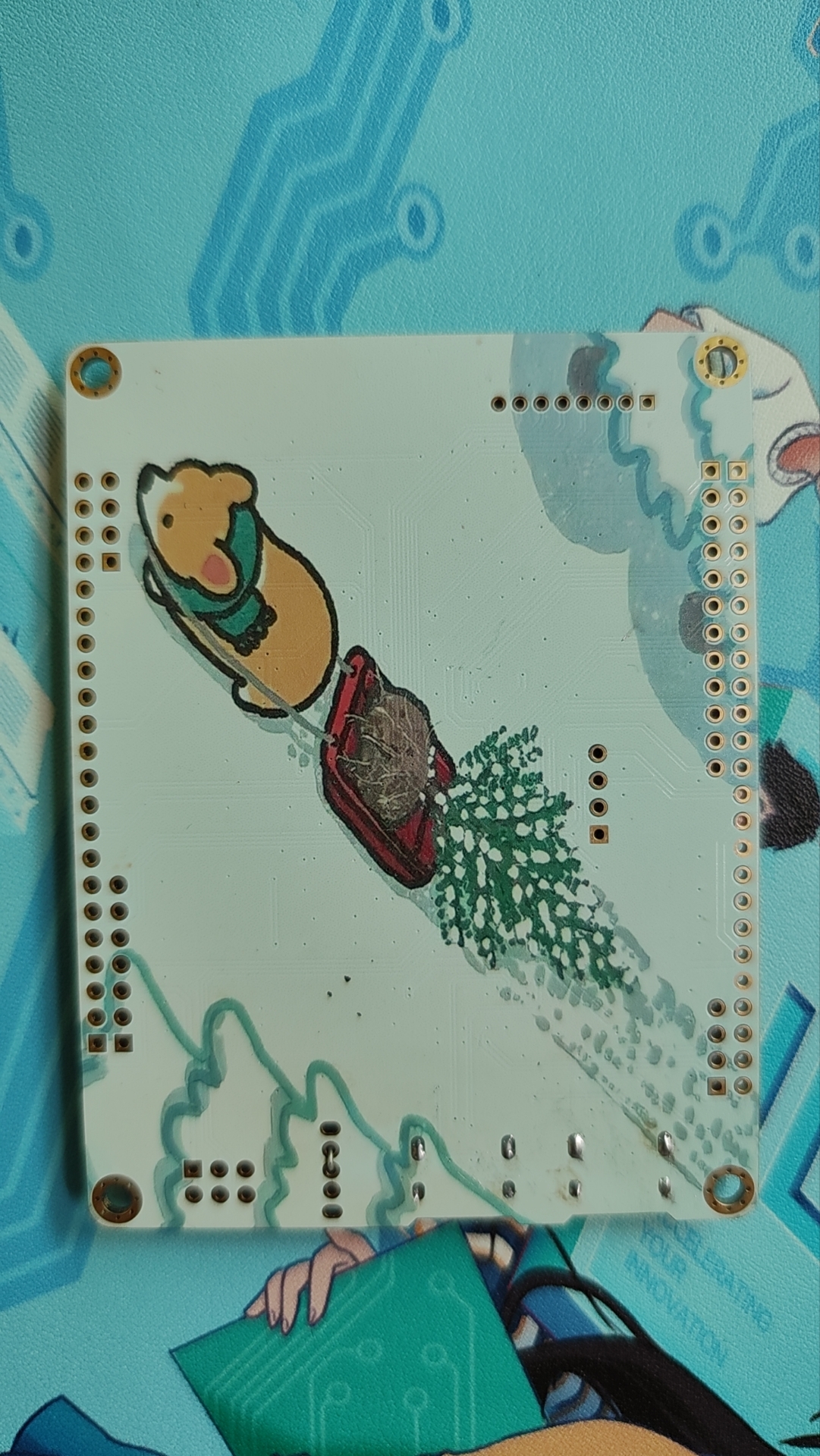
Top and bottom views of the actual board:

PDF_STM32F103RCT6 Simple Core Board.zip
Altium_STM32F103RCT6 Simple Core Board.zip
PADS_STM32F103RCT6 Simple Core Board.zip
BOM_STM32F103RCT6 Simple Core Board.xlsx
95557
VC-02 Voice Control Board
A voice control board based on the Anxinco VC-02 - April Fool's Day Limited Edition
References: https://docs.ai-thinker.com/voice_module
https://blog.csdn.net/Boantong_/article/details/124689101
Reference Project: VC-02 Offline Voice Desk Lamp Controller
Usage Notes: Although this module is easy to use, allows for customizable entries, and does not require special tools for burning, please note! Initial firmware burning via serial port (USB) has a very high probability of bricking the device (infinite reboots), and there is only one solution---purchase an Ai-Thinker JTAJ programmer (as of the time of open source, according to feedback from group members, older chips still have this bug).
Project Introduction:
This project uses the Ai-Thinker VC-02 voice module, supports burning custom reply words, can edit "foolish and amused" entries, and control IO port operations. Module Features:
Supports Chinese and English bilingual control;
supports AEC echo cancellation and steady-state noise reduction
; supports wake-word self-learning without firmware compilation;
overall recognition rate reaches over 98%
; stable and easy-to-use cloud platform.
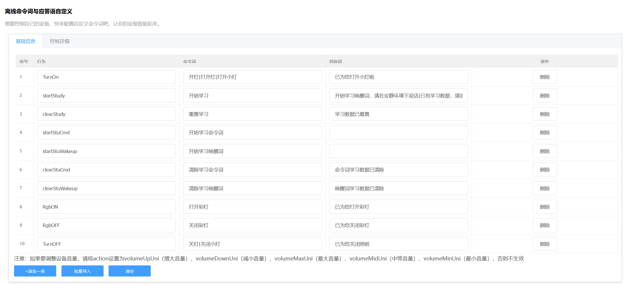
Project Functions:
This project uses an offline voice solution to implement existing control functions
; supports on/off colored light functions
; colored LED ring light;
fun Q&A; customizable
pin configuration.
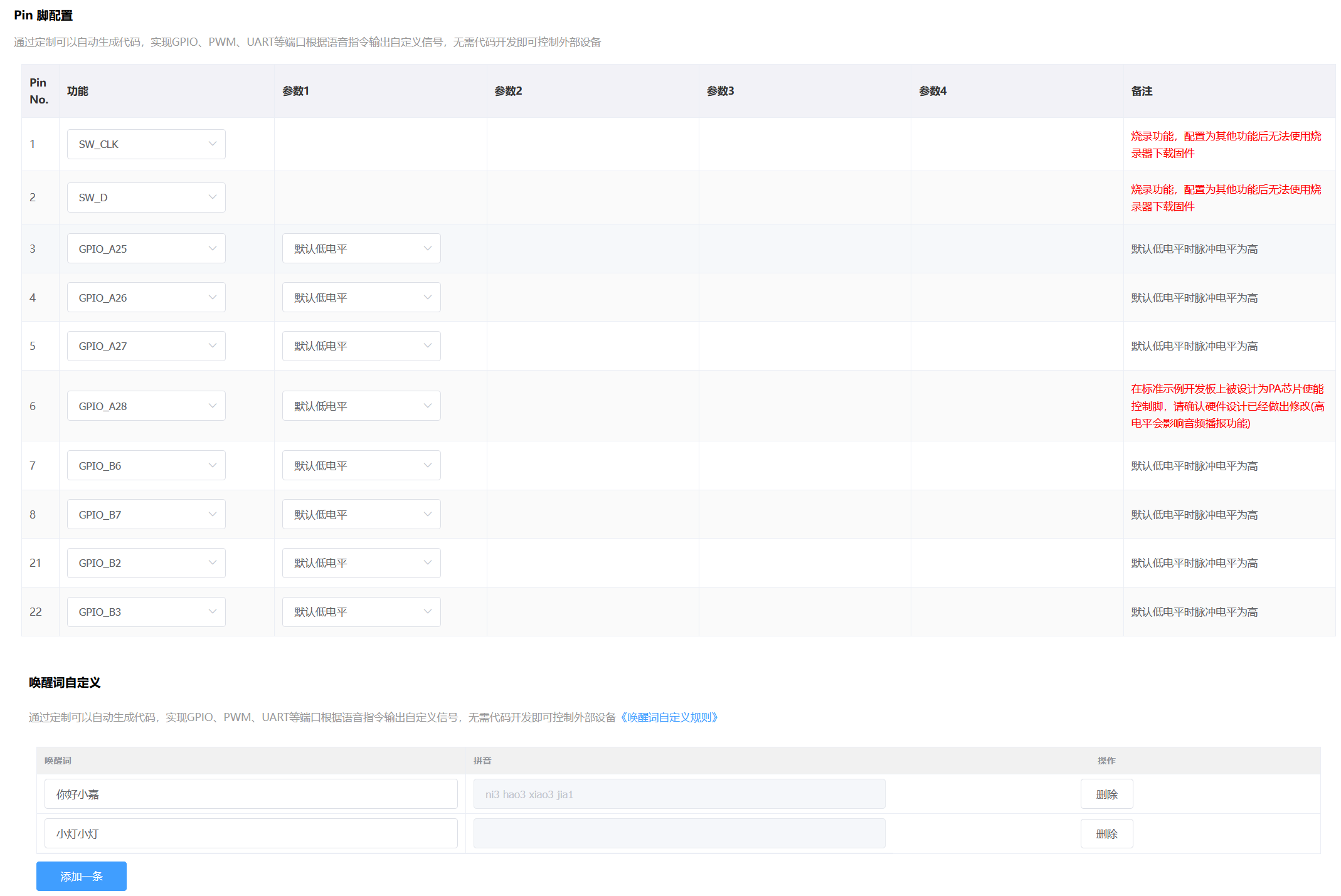
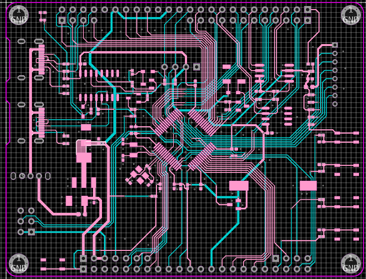
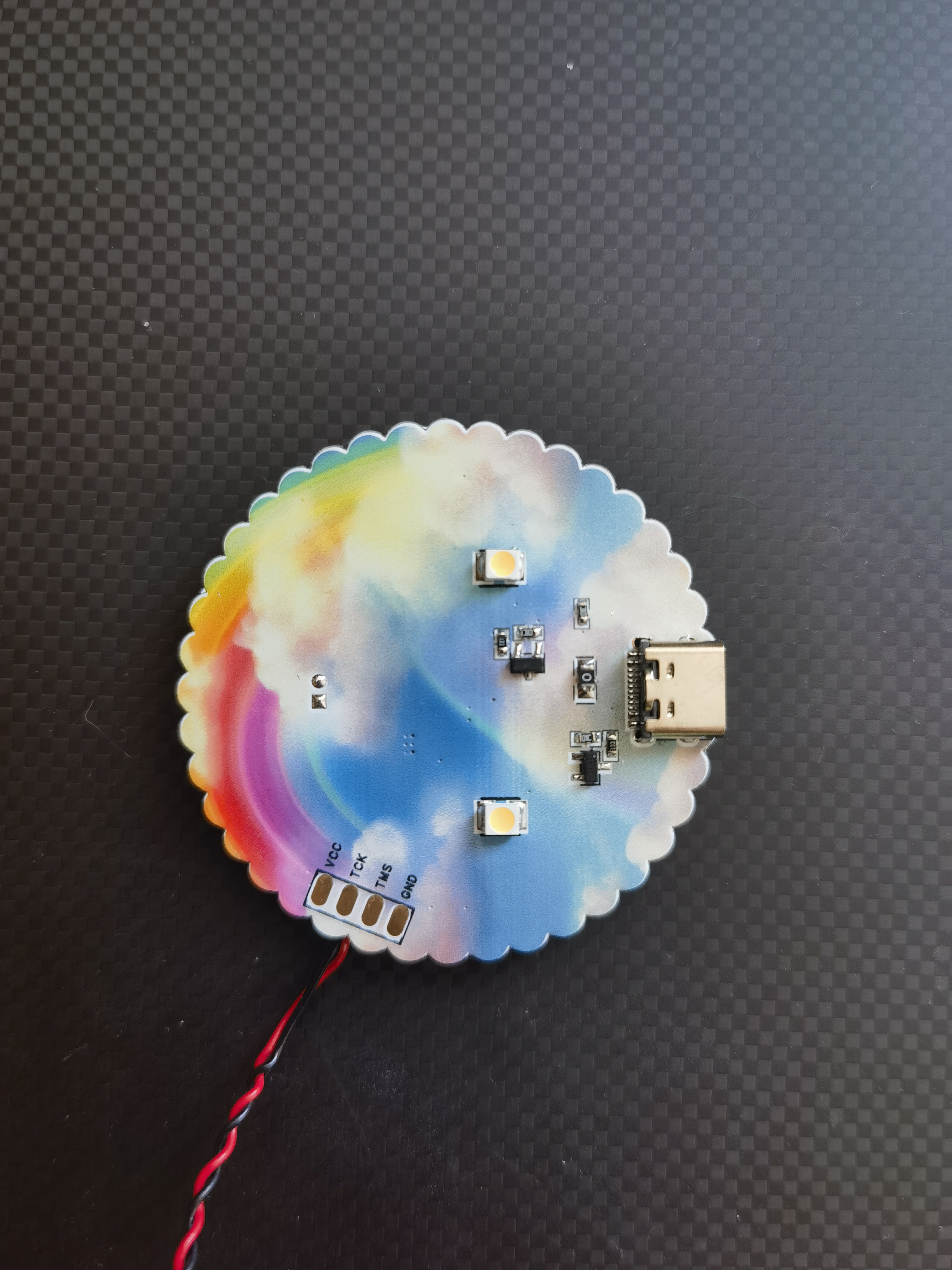
Project Images

output.tar.gz
PDF_VC-02 Voice Control Board.zip
Altium_VC-02 Voice Control Board.zip
PADS_VC-02 Voice Control Board.zip
BOM_VC-02 Voice Control Board.xlsx
95558
electronic
 For entertainment purposes only!


 京公网安备 11010802033920号

 212P1002N328SN


