A Bilibili video

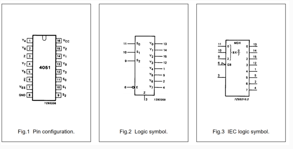
demonstrating a pocket oscilloscope based on the Liangshan School model : https://www.bilibili.com/video/BV1tf421Z7xs ( Links to some components are also provided) . Purchase links for some components: [DC-DC power chip SGM3204YN6G/TR: https://item.taobao.com/item.htm?_u=o34jmok82036&id=675663252083&spm=a1z09.2.0.0.31aa2e8dy4xiVy&skuId=5034286035115 DC-DC power chip SGM3204YN6G/TR Saint-Gobain SOT-23-6 charge pump chip 200mA - Taobao (taobao.com)] 6.5pF-30pF Adjustable Capacitor: https://detail.tmall.com/item.htm?_u=o34jmok8424e&id=599156749733&spm=a1z09.2.0.0.31aa2e8dy4xiVy&skuId=4349366994999 TZC3P300A110R00 Surface Mount Variable Adjustable Capacitor 3x4 30pF 6.5pF-30pF 100V -tmall.com Tmall Screen: Purchase Link: https://detail.1688.com/offer/735007928325.html?spm=a360q.8274423.0.0.7b854c9a1xZzQt 2.4-inch TFT LCD color screen ST7789v LCD display 240*320 ILI9341 SPI serial port 18Pin (1688.com) Hardware AC/DC coupling circuit . The signal relay is connected across the coupling capacitor. When the relay is not working, the coupling capacitor provides coupling. Due to the capacitor's characteristic of passing AC and blocking DC, only AC signals are detected by the subsequent circuit. When the relay is working, the coupling capacitor is short-circuited and directly coupled, allowing all signals to be detected by the subsequent circuit. The smaller the coupling capacitor, the easier it is for high-frequency signals to pass, but the more severe the distortion of low-frequency signals. Conversely, the larger the coupling capacitor, the more normal the low-frequency signals are, but the distorted high-frequency signals are, and the signal will be delayed. Here, we use the microcontroller's internal ADC (2M sampling), so a 100nF capacitor is used for coupling. (Based on the calculation of the subsequent voltage divider circuit, fp=1/2πRC). The signal relay driver coil selected here has positive and negative terminals. The coil driving voltage is 5V, and the driving current also needs to be considered. For other detailed information, please refer to the corresponding documentation. To meet the 1MΩ signal impedance matching requirement, the voltage divider circuit uses a large resistor for voltage division. The capacitor next to the voltage divider resistor plays an important role in AC signal coupling. The 6.5pF~30pF adjustable capacitor is used to adjust the signal compensation capacitor of the oscilloscope. Different signal losses due to deviations in the actual circuit require the use of an adjustable capacitor to compensate for the signal. Excessive or insufficient compensation will lead to waveform distortion. The programmable operational amplifier signal processing circuit consists of an 8-channel single-select analog switch chip 74HC405 and a dual operational amplifier chip TLV2372. The 74HC405 chip is equivalent to an 8-channel single-select switch, with on-resistance that varies with the signal frequency and voltage. The 74HC4051 is a high-speed CMOS device with 8 built-in analog input/output pins (Y0~Y7), 3 digital input pins (A0~A2) for selecting a channel, a common input/output terminal Z, and an enable terminal E. When the enable pin E is low, one channel is selected via A0~A2, and that channel is in a low-impedance on state. When E is high, the A0~A2 settings are invalid, and all pins are in a high-impedance off state. VDD and VEE are connected to the power supply voltage of the digital control input, with a range of 3~9V. Analog input/output can vary between the highest voltage VDD and the lowest voltage VEE, but VDD~VEE will not exceed 9V. For multiplexer switches, VEE and VSS are connected together, i.e., grounded. The 74HC4051 is mainly used for analog multiplexer switches, digital multiplexer switches, and signal gating. Pin descriptions: Enable, address selection, and channel relationship . Dual operational amplifier chip TLV2372 . The TLV2372IDR single-supply operational amplifier features rail-to-rail input and output capabilities. The TLV2372IDR has a minimum operating supply voltage as low as 2.7V over the extended industrial temperature range, while also adding rail-to-rail output swing characteristics. The TLV237x provides 3MHz bandwidth from as low as 550µA. With a maximum recommended supply voltage of 16V, the device can be powered by a variety of rechargeable batteries (supporting supplies from ±8V down to ±1.35V). Its CMOS input characteristics, suitable for high-impedance sensor interfaces, and low-voltage operation make it an ideal replacement for the TLV227x in battery-powered applications. A rail-to-rail input stage further enhances its versatility. The TLV237x is the seventh device in TI's rapidly expanding RRIO product line and the first to offer excellent AC performance and support power rails up to 16V. The TLV2372IDR is packaged in an SOIC-8 package. The TLV2372IDR parameter pin diagram shows a programmable operational amplifier (OPA) for signal processing. The microcontroller controls the S1, S2, and S3 pins of the 74HC405 to control the on-resistance (the AGND pin of the 74HC405, connected to the E# pin, is always low). Dual operational amplifiers handle signal scaling and shifting, respectively, processing the analog signal from the pre-stage voltage divider and ensuring the processed signal remains within the 0-2.5V range for microcontroller ADC acquisition. A first-stage OPA scales the amplified signal and serves as the input to a second-stage OPA, which then shifts the amplified signal. A single operational amplifier is used in the waveform generator output voltage follower circuit as the voltage follower output, primarily to isolate the microcontroller's DAC output. Theoretically, the DAC signal can also be directly output (the DAC contains an internal buffer circuit to improve output capability). The negative voltage circuit uses a charge pump chip, the SGM3204YN. The SGM3204 is a charge pump voltage inverter designed to operate within an input voltage range of 1.4V to 5.5V. The SGM3204 offers up to 200mA of output current. Typical conversion efficiency exceeds 80% over a wide output current range. Its wide supply voltage makes it ideal for a variety of applications powered by a single lithium-ion battery and two or three NiCd, NiMH, or alkaline batteries. The shutdown current is less than 1μA. This device requires one bridging capacitor and two small bypass capacitors to function as a complete charge pump inverter, making it ideal for numerous battery-powered and board-level applications. The SGM3204 is housed in a green SOT-23-6 package. Its operating temperature range is -40°C to +85°C.


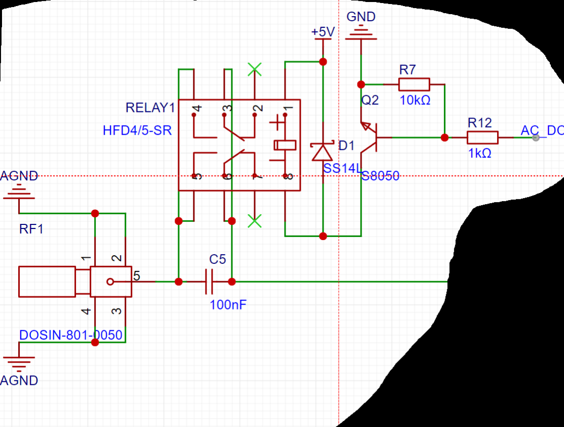


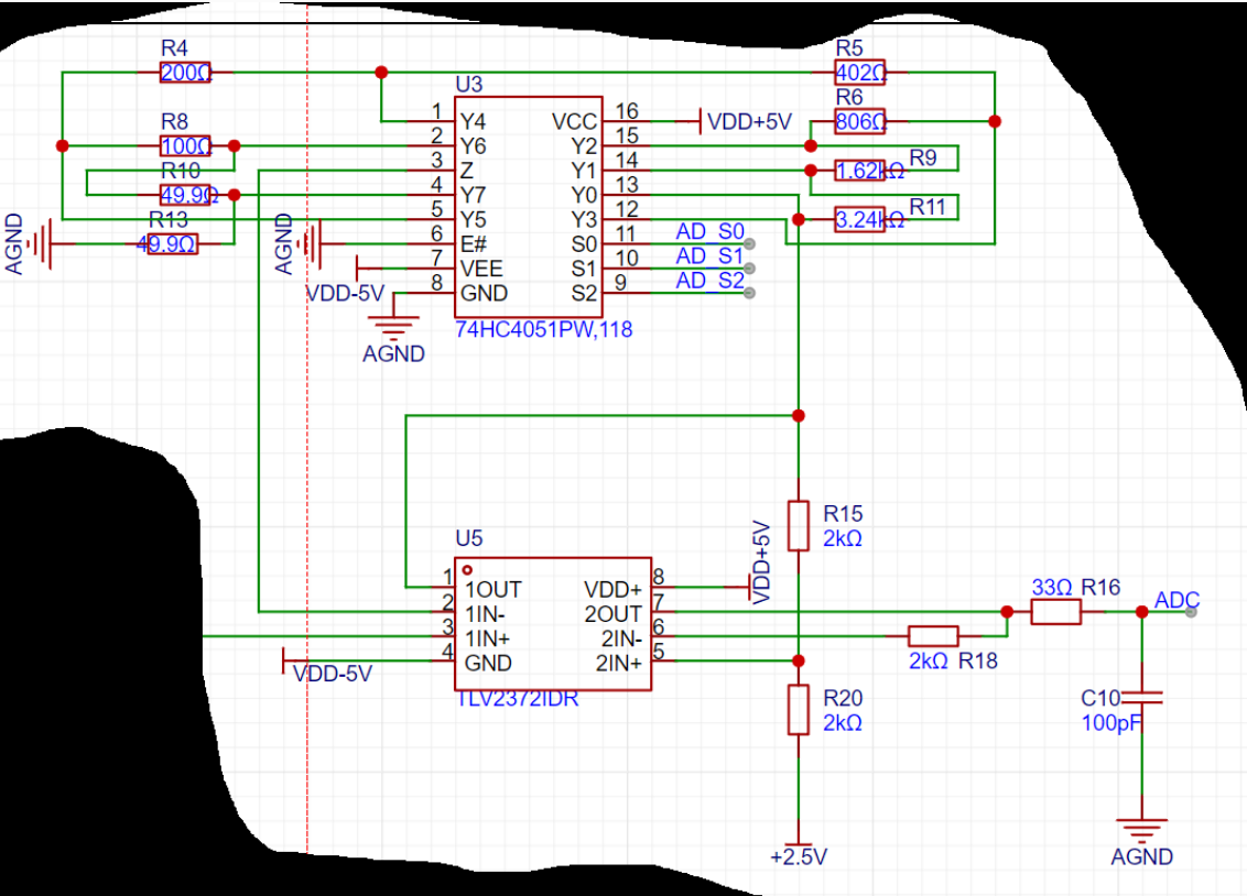


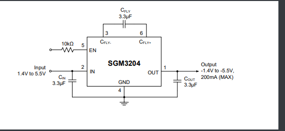
A charge pump negative voltage chip is used to convert 5V to -5V to power the VSS of the operational amplifier, forming a dual-supply operational amplifier circuit, ensuring the linearity of the operational amplifier.

The reference source circuit
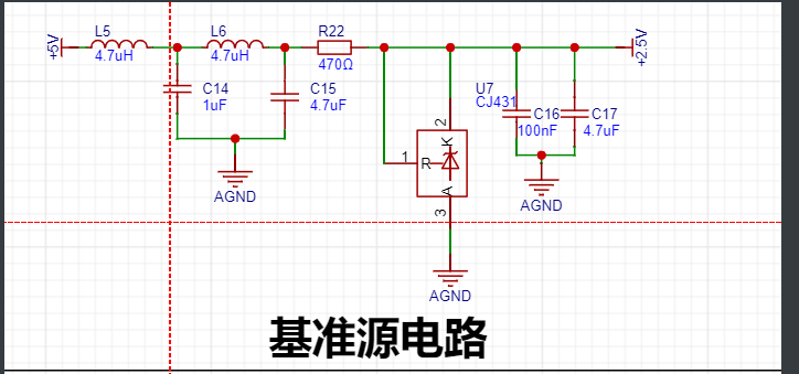
provides a stable reference voltage. Here, a 2.5V voltage reference is chosen for the operational amplifier shift circuit and also provides a reference for the ADC. The CJ431 reference chip's Ika is typically 10mA for stable operation, so a 470Ω current-limiting resistor is chosen.
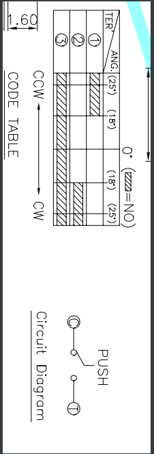
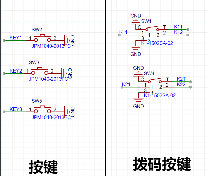
The button
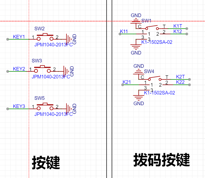
circuit uses two types of buttons: three independent buttons on the front and two DIP switches on the back. The dial button has three trigger states: up, down, and down. The dial trigger mechanism is shown in the diagram below.
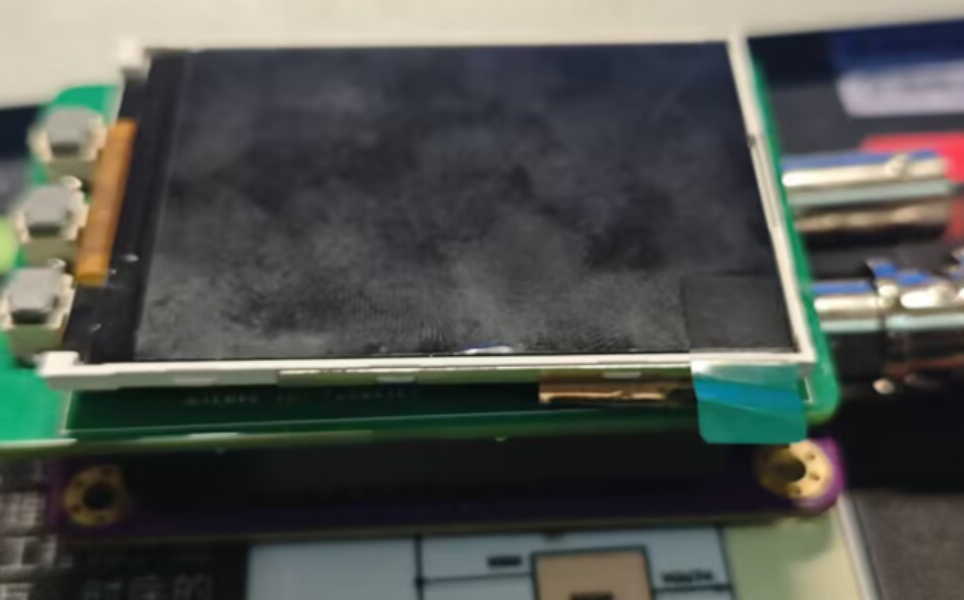
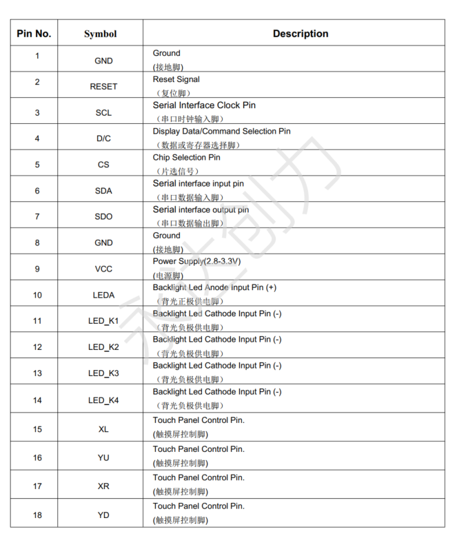
The screen display circuit
uses a 2.4-inch SPI screen (42.72*60.26mm). The SPI screen ILI9341 driver is simple, and the output I/O can be effectively separated from the analog circuit.

The screen pin
software uses
LED

DMA to transfer screen data, LED2 toggles, and DMA completes ADC acquisition of LED3 toggles

the GPIO configuration function.
The function `led_gpio_config` is used to configure the GPIOs for LEDs.
The `rcu_periph_clock_enable` function enables the clocks for four GPIO ports: GPIOD, GPIOE, GPIOG, and GPIOA.
The `gpio_mode_set` function configures the four GPIO ports to output mode (GPIO_MODE_OUTPUT) with pull-up mode (GPIO_PUPD_PULLUP).
The `gpio_output_options_set` function sets the output options for the four GPIO ports, including push-pull output type (GPIO_OTYPE_PP) and output speed of 50MHz (GPIO_OSPEED_50MHZ).
Specific port and pin configurations are as follows:
Pin 5 of GPIOA is configured as an LED output.
Pin 7 of GPIOD is configured as an LED output.
Pin 3 of GPIOE is configured as an LED output.
Pin 3 of GPIOG is configured as an LED output.
The USART

Type-C port is connected to USART0. The serial port is used for debugging, printing information,

configuring USART (serial port) GPIOs, and sending data. This includes the initialization configuration function `usart_gpio_config`, the function to send a single character `usart_send_data`, and the function to send a string `usart_send_string`. It also provides the `fputc` function to support standard output to the serial port.
The following is a detailed summary of the code:
The `usart_gpio_config` function configures the USART's GPIOs. The
`rcu_periph_clock_enable` function enables the USART's TX and RX ports and the clock for the USART peripheral. The `gpio_af_set` function sets the
multiplexing
function for the TX and RX pins. The `gpio_mode_set` function configures the TX and RX pins to multiplexed mode and sets the pull-up mode.
The `gpio_output_options_set` function sets the output options for the TX and RX pins, including push-pull output type and output speed of 50MHz.
The USART peripheral's initialization function `usart_deinit` is called, configuring parameters such as baud rate, parity, data bit length, and stop bits.
Finally, the USART peripheral and serial port transmission functions are enabled.
The `usart_send_data` function is used to send a single character data.
The `usart_data_transmit` function is called to send a single character data.
The data transmission is waited for to complete by checking the USART transmit buffer empty flag (`USART_FLAG_TBE`).
The `usart_send_string` function is used to send string data.
The `usart_send_data` function sends characters in the string one by one until the end-of-string character is encountered.
The `fputc` function is a standard library function used for character output.
This function calls the `usart_send_data` function to send a character and returns the sent character. Three ordinary
buttons
are used for DC/AC coupling switching, start/pause switching, and FFT switching, respectively. Two DIP switches are used to adjust certain parameters or increase/decrease functions.

The `key_gpio_config` function is used to configure the button's GPIO.
The `rcu_periph_clock_enable` function enables the clocks of four GPIO ports: GPIOD, GPIOC, GPIOG, and GPIOA.
The `gpio_mode_set` function configures each button pin to input mode and sets the pull-up mode.
Each button is connected through a different GPIO port and pin: KeyUp, KeyOn, KeyDown, KeyAUp, KeyAOn, KeyADown, KeyBUp, KeyBOn, and KeyBDown.
Button usage:
Button detection

is performed in a timer interrupt to ensure timely triggering. To maximize timer utilization, polling is performed directly within the 50ms screen refresh cycle.
The `main` function


defines the button functions as follows:
KeyUp, KeyOn, and KeyDown: These are function keys used to control the instrument's operation. Specific functions may include switching menus and confirming selections.
KeyAUp, KeyAOn, and KeyADown: These are DIP switches (A), used to adjust certain parameters or increase/decrease functions.
KeyBUp, KeyBOn, and KeyBDown: These three buttons are DIP switches (B), also used to adjust certain parameters or functions.
Button detection and handling:
In the main function, the button detection and handling are performed using the timer interrupt handler TIMER3_IRQHandler.
Each time the timer triggers, the state of the corresponding GPIO pin is checked to determine whether a button is pressed.
A key array is set for each button, with each bit corresponding to a button. When a button is pressed, the corresponding bit is cleared, and the button is checked again in later processing to ensure it remains pressed, thus enabling a long-press function.
Button function implementation:
For function keys (KeyUp, KeyOn, KeyDown), pressing the button executes the corresponding function, such as start/pause acquisition or menu switching.
For DIP switches (KeyAUp, KeyAOn, KeyADown, KeyBUp, KeyBOn, KeyBDown), pressing the button changes the corresponding parameter value or function state to adjust certain functions of the instrument.
Button state detection:
A key time threshold (Key_Time) distinguishes between short and long presses. When a button is pressed and the duration reaches a certain time, the button state is updated to a long-press state for subsequent operations.
Button response delay:
After each button detection, there is a delay to allow the button state to stabilize, preventing accidental operation due to button bounce.
SPI

uses DMA for SPI2 data transfer, thus implementing the data read/write functionality of the SPI2 interface and improving data transfer efficiency through DMA.

SPI2 Initialization:
In the `Spi2_Init` function, the clocks for GPIOC and SPI2 are first enabled.
Then, the multiplexing function and mode of the GPIOC pins are set, configuring them as functional pins for SPI2.
Next, the operating parameters of SPI2 are configured, including transmission mode, device mode, data frame size, clock polarity and phase, NSS mode, prescaler, and pin order.
Finally, the `spi_init` function applies the above configuration to SPI2 and enables SPI2.
SPI2 Data Read/Write:
The `Spi2_ReadWriteByte` function is used to send and receive one byte of data to and from SPI2.
Before sending data, it polls until the transmit buffer is empty (TBE flag).
After receiving data, it similarly polls until the receive buffer is not empty (RBNE flag).
SPI2 Data Read:
The `Spi2_Read` function is used to receive one byte of data from SPI2.
In this function, it polls until the receive buffer is not empty (RBNE flag), then reads the received data and returns.
SPI2 Data Write:
The Spi2_Write function is used to send one byte of data to the SPI2.
Within the function, it waits for the transmit buffer to be empty (TBE flag) by polling, and then writes the data into the transmit buffer.
SPI2 DMA Initialization:
The Spi2_Dma_Init function is used to initialize the SPI2 DMA function.
First, the DMA clock is enabled, and the 5th channel of DMA0 is initialized.
The DMA transfer direction is set to from memory to the peripheral, the source address is set to 0, and the destination address is set to the SPI2 data register address.
Parameters such as the DMA data transfer amount, the incremental mode of memory and peripheral addresses, the data width, and the transfer priority are set.
Then, the circular transfer mode is disabled, SPI2 is selected as the DMA peripheral, and the DMA transfer completion interrupt is enabled.
Finally, the interrupt for DMA0 channel 5 is enabled via NVIC.
LCD Screen:
The LCD screen is ported based on the code provided by the vendor, but attention should be paid to the screen driver, whether it is ILI9341 or ST7789. The following is a function analysis; please refer to the code for
LCD screen initialization, data writing, and DMA data transfer configuration. The following is a detailed analysis of the code:
GPIO Initialization:
The `LCD_GPIO_Init` function initializes the GPIO pins required for the LCD screen.
Pin PA15 controls the backlight, initialized to output mode and with the backlight off.
Pins PD2, PD3, and PD6 control the LCD's chip select, data/command selection, and reset, also initialized to output mode.
SPI Communication:
Data transmission to the LCD screen is completed via the SPI2 interface, configured using the `Spi2_Init` function.
Data writing is implemented through the `LCD_Writ_Bus` function, which transmits data to the LCD screen via SPI2.
LCD Initialization:
The `LCD_Init` function initializes the LCD screen, selecting a different LCD screen (ILI9341 or ST7789) based on the value of `Chip_Selection`.
First, GPIO is initialized, then the LCD screen undergoes a hardware reset.
Next, different initialization command sequences are sent according to the LCD screen model to complete the LCD screen initialization configuration.
LCD Data Writing:
The `LCD_WR_DATA8` and `LCD_WR_DATA` functions are used to write 8-bit and 16-bit data to the LCD screen.
The `LCD_WR_REG` function is used to write the register address to the LCD screen.
The `LCD_Address_Set` function is used to set the display area of the LCD screen.
Clearing the screen and displaying data:
The `LCD_Fill` function is used to clear a specified area of
the LCD screen and fill it with a specified color. The `LCD_Show_Gram` function is used to display specified image data on the
LCD screen. The `DMA0_Channel5_IRQHandler` function is the interrupt handler for DMA channel 5, used for processing after DMA transfer is complete, and controlling the chip select of the LCD screen.
The code implements the LCD screen's initialization configuration, data writing, screen clearing, and data display functions, and achieves efficient data transfer through SPI2 and DMA.
The UI interface
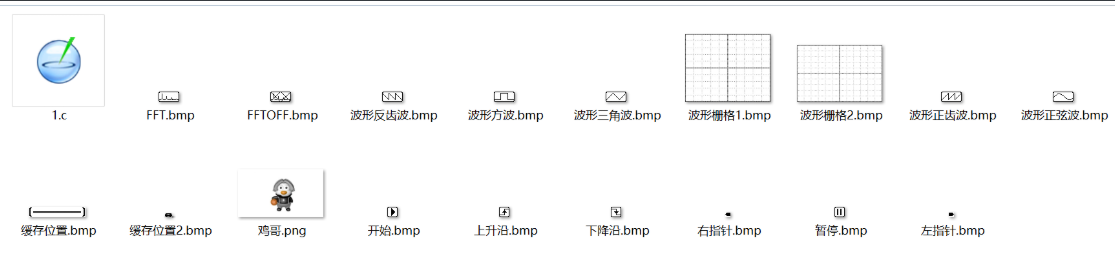
is implemented after the LCD code is ported. Software is used to extract the image's modulus into an array; details of the array can be found in `bsp_bmp.h`.

Waveform code analysis for controlling and displaying the LCD screen
: Global variables: Define global variables and arrays to store graphic data, waveform data, and settings.
Function declaration:
`Lcd_Show_Time()`: Initializes a timer to periodically update the LCD display.
`Lcd_Gram_Fill()`: Fills the LCD display buffer with the specified color.
`Lcd_Show_Lin()`: Draws a vertical line on the LCD display buffer.
`Lcd_Show_Bmp()`: Displays a black and white bitmap image on the LCD display buffer.
`LCD_Gram_Bmp()`: Displays the startup logo image on the LCD display buffer.
`LTDC_Draw_Point()`: Draws a single pixel on the LCD display buffer.
`LCD_ShowChar()`: Displays a character on
the LCD display buffer. `LCD_ShowString()`: Displays a string on the LCD display buffer
. `LCD_Pow()`: Calculates a power of a number. `LCD_ShowNum()`:
Displays a number on the LCD display buffer. `LCD_Show_Wav()`:
Displays waveforms and control elements on the LCD display buffer. `LCD_Show_Data()`: Controls
the display of various elements based on input parameters.
`Key_Make_Set()`: Controls various settings and actions based on input parameters.
Main Functionality:
The program may run in a loop, continuously updating the LCD display based on user input or system events.
User interaction is handled through functions like `Key_Make_Set()`, which responds to key presses by adjusting settings or triggering actions.
Waveforms and control elements are drawn on the LCD using functions like `LCD_Show_Wav()`.
This program provides the ability to display text, numbers, images, and waveform data on an LCD screen.
It also appears to support various user settings, such as waveform type, trigger settings, sampling rate, etc., which can be adjusted through the user interface. The program includes an
ADC

and related peripherals for sampling analog signals.

Global variables for data acquisition are defined, including an array `adc_value` for storing ADC data, a variable `adc_dma_AB` for recording data slices, a variable `adc_dma_ok` for updating flags, and a temporary array `adc_buff` for data transfer.
The function `adc_config()` configures the ADC, DMA, and timers. It includes the following steps:
enabling the clocks for GPIOA, ADC, TIMER1, and DMA1;
configuring the GPIOA pins to analog mode;
configuring TIMER1 to PWM mode to trigger ADC sampling;
configuring DMA1 channel 0 to transfer ADC sampled data to the `adc_value` array;
and configuring the ADC's rule conversion channel, sampling time, external trigger source, etc.
Enable DMA transfer for the ADC and enable the ADC interface.
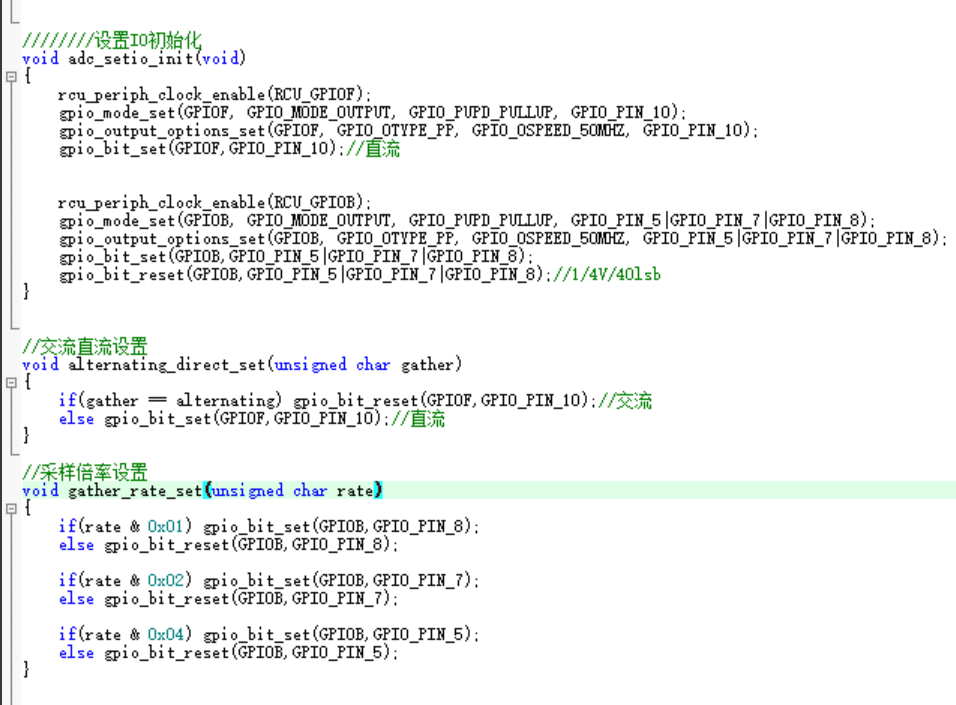
The function `adc_setio_init()` initializes the ADC-related GPIO pins. It sets the GPIOF pin to output mode and the GPIOB pin to output mode, and sets the status of the GPIOB pin to set the AC or DC sampling mode and the sampling rate.
The function `alternating_direct_set(unsigned char gather)` sets the sampling mode to AC or DC.
The function `gather_rate_set(unsigned char rate)` sets the sampling rate.
The function `adc_speed_set(unsigned char speed)` sets the sampling speed, i.e., the prescaler value of timer TIMER1.
The function `adc_power_set(unsigned char onoff)` starts or stops ADC sampling by controlling the enable state of TIMER1.
The DAC

generates specific waveforms and uses DMA and timers to control the output frequency and waveform data.

Global variables: A `convertarr` array of length 100 is defined to store waveform data.
Function `dac_config()`: This function configures the DAC, DMA, and timers. It includes the following steps:
Enable the GPIOA port and configure PA5 as an analog input.
Enable the DAC and configure the trigger source as Timer 6 (DAC_TRIGGER_T6_TRGO).
Configure the DAC output buffer and DMA.
Enable DMA and configure DMA channel 6, setting the DMA transfer direction, data size, priority, etc.
Enable Timer 6 and configure the timer's prescaler, auto-reload value, and trigger source.
Function `Dac_Time_Hz(uint16_t hz)`: This function sets the DAC output frequency. Depending on the input frequency `hz`, it sets the timer's prescaler and auto-reload value for different ranges to achieve different output frequencies.
Function `Dac_Show_Wav(uint8_t number)`: This function sets the waveform data to be output. Based on the input waveform number, it selects the corresponding waveform from predefined waveform data and stores it in the `convertarr` array.
The `main` function
includes ADC data acquisition, FFT transformation, LCD display control, and key input processing.

Global variables: Several global variables are defined, including a temporary pointer to ADC data (`adc_tmp`), input/output arrays needed for FFT operations, and variables used to control the FFT display.
Initialization: The `main()` function configures the system clock, initializes peripherals (LED, USART, SRAM, LCD, SPI, DAC, ADC, etc.), and initializes timers.
Main loop: The main loop contains the following main functions:
LCD display update: Timed refresh of the LCD is achieved through timer interrupts to ensure timely screen updates.
ADC acquisition: Determines whether ADC acquisition is enabled; if enabled, waits for acquisition to complete before performing FFT operations.
FFT operation: Performs FFT transformation on the data acquired by the ADC, calculates the amplitude of the FFT spectrum, and determines the waveform display range based on the amplitude.
Keypad Handling: Detects keypad input and performs corresponding operations based on the key pressed, such as start/pause acquisition, switching waveform display, adjusting trigger position, and adjusting FFT display parameters.
Timer and DMA Interrupt Handling: Uses timer interrupts to refresh the LCD and DMA interrupts to transfer ADC data and set the acquisition completion flag.
AC/DC Switching and Amplification Factor Switching.

AC/DC switching is achieved by controlling AC_DC (PF10), and the amplification factor is adjusted by controlling AD_S0 (PB8), AD_S1 (PB7), and AD_S2 (PB5).
The FFT porting and use of
the ported RAM company's DSP library, combined with the GD32F450's built-in FPU floating-point acceleration, makes FFT calculations fast and accurate.
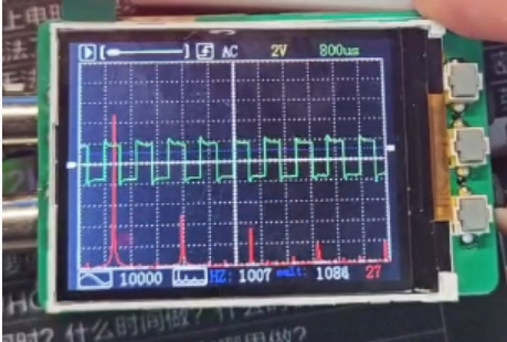
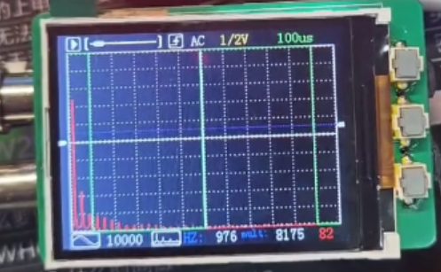
1. Simple Introduction to the Principle of FFT:
FFT, short for Fast Fourier Transform, can transform a time-domain signal (waveform - time x value) into a frequency-domain signal (spectrum - frequency point x amplitude). Specific algorithms can be found online; this section mainly introduces the fast implementation of the FFT algorithm in the DSP library.

As shown in the figure, FFT can quickly and effectively analyze the composition of waveforms and the proportion of different frequencies. It is also often used for music spectrum display, noise filtering, data adjustment, and other fields. Maximum percentage frequency = Maximum amplitude frequency * Sampling period / FFT calculation points 1024; (Slight error exists) (Step error effect, minimum error = sampling frequency / 1024, reducing the sampling frequency will slightly improve the calculation accuracy)
2. For details on porting the DSP library
, please refer to the DSP library porting documentation on the GD official website, or the DSP library porting documentation for STM32F4, as they both use the ARM core DSP library. This tutorial is for reference only; different Keil versions and libraries may vary slightly.
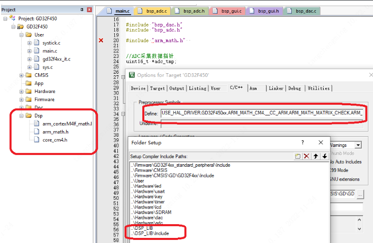
2.1. Add the official RAM DSP library files to the project

. 2.2. Open the project and add the compiler macros and library files:
USE_HAL_DRIVER, GD32F450xx, ARM_MATH_CM4, __CC_ARM, ARM_MATH_MATRIX_CHECK, ARM_MATH_ROUNDING
2.3. Use FFT in the code:
#include "arm_math.h"
//FFT variable
#define FFT_LENGTH 1024 //FFT length, default is 1024 points FFT
float fft_inputbuf[FFT_LENGTH*2]; //FFT input array
float fft_outputbuf[FFT_LENGTH]; //FFT output array
arm_cfft_radix4_instance_f32 scfft;
//FFT initializes the scfft structure once
arm_cfft_radix4_init_f32(&scfft,FFT_LENGTH,0,1);
//FFT operation
for(i=0;i>4);
if(Show_LinA[i] > 227) Show_LinA[i]=227-8;
else if(Show_LinA[i] < 27) Show_LinA[i]=27-8;
else Show_LinA[i]=Show_LinA[i]-8;
}
//FFT operation<1ms
for(i=0;i max_fft) max_fft = fft_outputbuf[i];
}
//Automatically evaluate FFT scaling level
fft_n = max_fft/150 + 1; //Only display 150 scales
for(i=0;i<320;i++)
{
Show_LinB[i]=(fft_outputbuf[i]/fft_n +27);
if(Show_LinB[i] > 227) Show_LinB[i]=227-8;
else if(Show_LinB[i] < 27) Show_LinB[i]=27-8;
else Show_LinB[i]=Show_LinB[i]-8;
}
//Display data
if(Show_AB) Lcd_Show_LinA(Show_GramA);
else Lcd_Show_LinA(Show_GramB);
//delay_1ms(200);
}
}


 京公网安备 11010802033920号

 SD823C


