Using AO3400 MOS tubes with LED indicators.
A reverse-mount LED version has been added for easier heat spreader soldering (not verified by PCB fabrication, but should be fine).
Group 701827620
PDF_3D printer driver bit expansion fan.zip
Altium_3D printer driver for extended fan.zip
PADS_3D printer driver for extended fan.zip
BOM_3D Printer Driver for Extended Fan.xlsx
95629
Smart chat face-changing mini machine
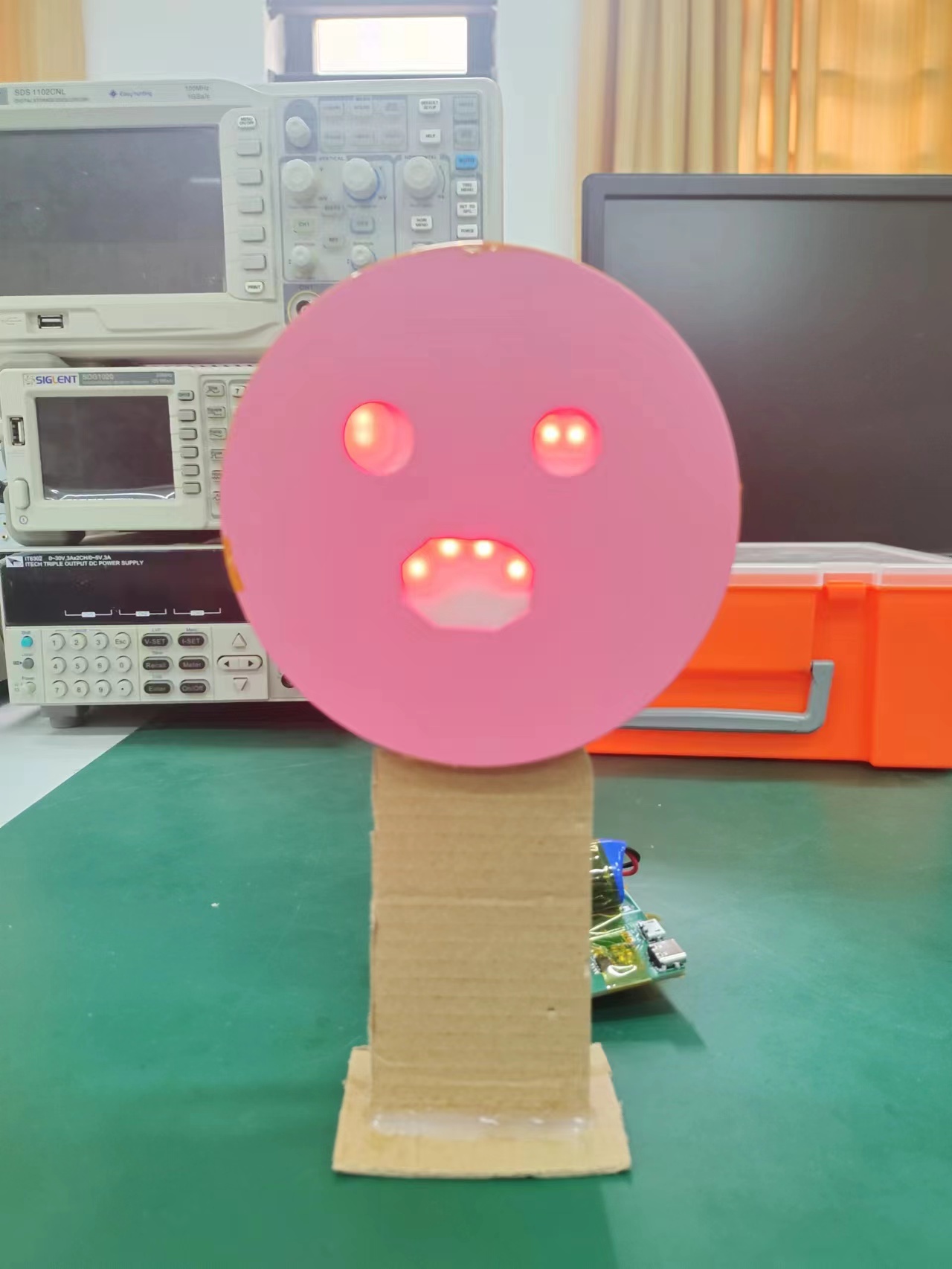
This is a small toy that uses the Tianwen ASRPRO voice chat feature. It has a power switch, supports charging via micro and Type-C interfaces, and can engage in conversation after being activated. Depending on your statements, the LED display will show Angela's current mood and provide corresponding responses.
This is a small voice chat toy using the Tianwen ASRPRO chip. It features a power switch and supports charging via micro and Type-C interfaces. The current wake-up word is "Angela" (this can be changed using the CH340 software). After waking up, you can engage in conversation. Depending on your words, LED indicators will display Angela's current emotion and provide a corresponding response. There are three emotions: happy, normal, and sad. Currently, the number of recognized phrases is limited; you can use your imagination to create your own personalized voice companion.
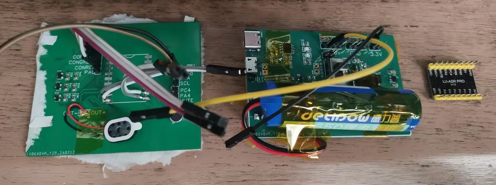
Main control: Tianwen ASRPRO voice chip.
Detailed instructions for using this chip, and downloadable supporting materials (https://www.haohaodada.com/new/bbs/forum.php?mod=viewthread&tid=592&page=1&extra=#pid1355).
Expression LED group: LED
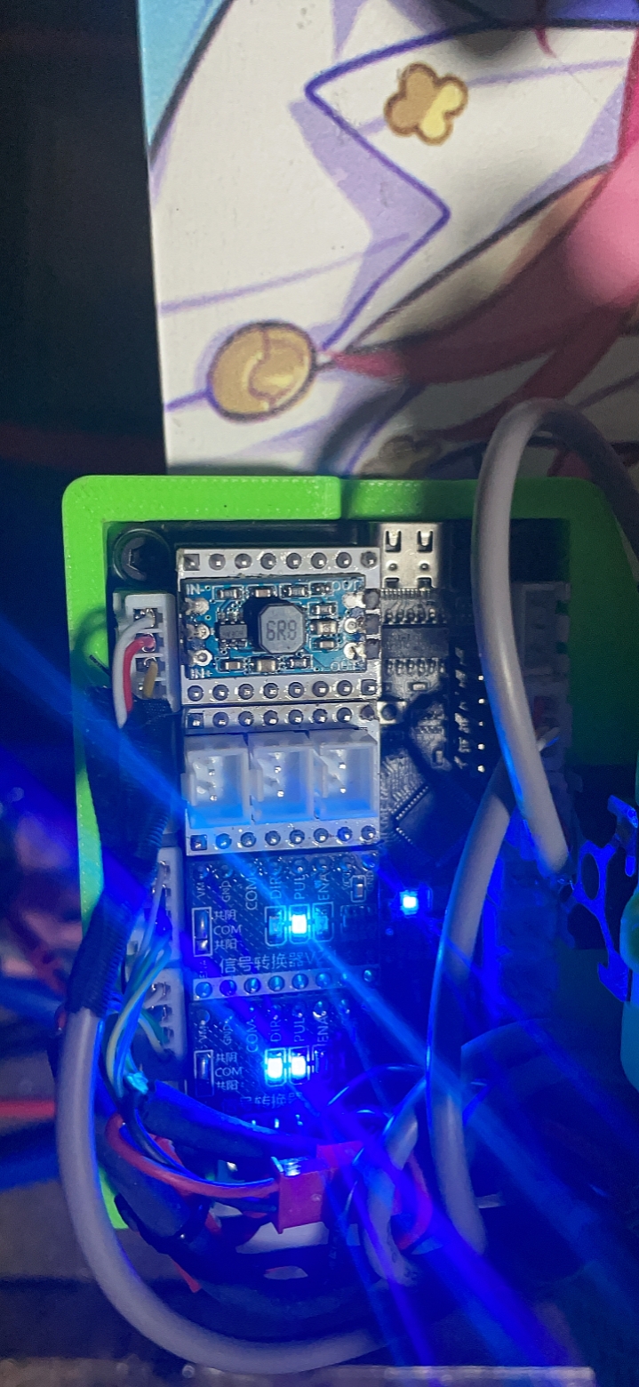
light group driver: PMOS switching circuit (for safety, I used a floating input instead of a high level).
(For details, please refer to the switching circuit section of this project: https://oshwhub.com/bzpass/solar-plant-automatic-cultivation-warehouse).
Power supply: Portable integrated module, charging, boost, and voltage regulation (For details, please jump to: https://oshwhub.com/bzpass/li-dian-chi-chong-dian-yu-guan-li).
Core overview:
Code section: The code is encoded using graphical programming, which is much simpler than STM32 library function programming.
Wake-up words and command words initialization:
0-20 are happy voice expressions;
20-40 are normal voice expressions;
after 40, it's sad voice expressions. Voice
input is not fully integrated; you can add your own
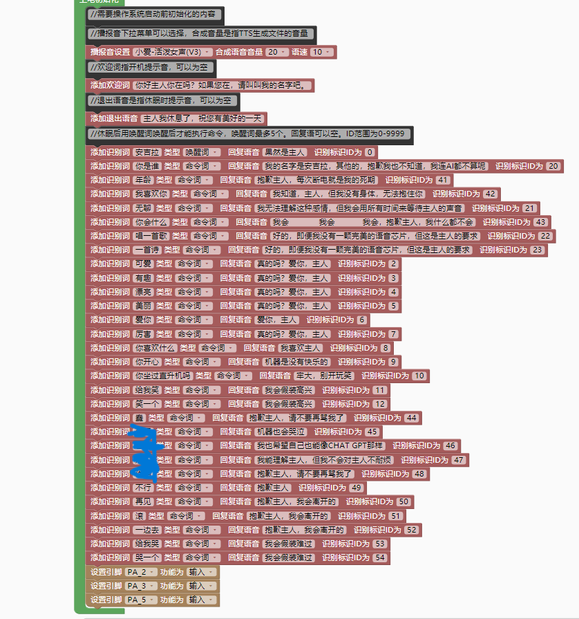
expression controls.

Actual test:
1. Happy;
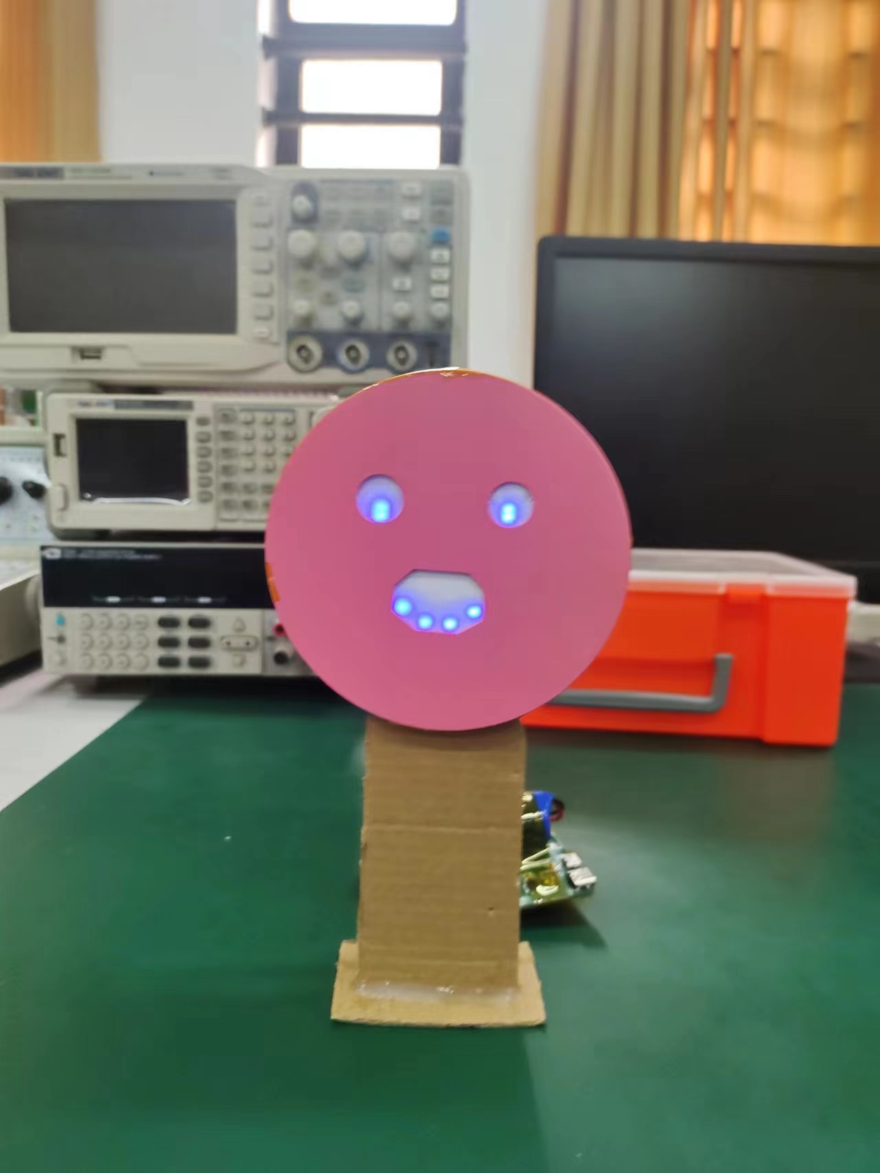
2. Normal
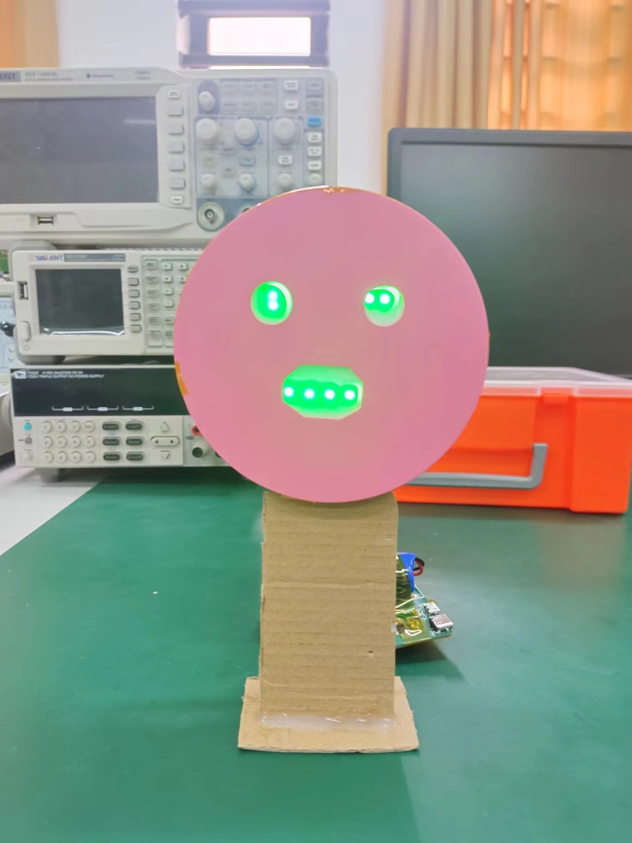
; 3. Sad
; 4. Test video
explanation: In practice, there were cases where the casing couldn't cover the components. One reason is that I soldered pin headers to the language module; otherwise, it could be directly attached to the light assembly board. The second reason is that the battery I chose was a bit too large. I suggest improving the 3D casing; it was my first time drawing a casing, and it was a complete mess.
Note: In actual testing, I used pins PA1, 2, and 3 to control the light assembly. However, due to hardware limitations, pin PA1 cannot drive the light assembly, so I changed the driving pins to PA2, 3, and 5. This improvement is shown in the schematic, but the problem is that the circuit board I'm currently using is the unmodified initial version. Therefore, the improved version hasn't been actually tested, but the changes are minor. If you're still concerned, please use pin headers and DuPont wires for connection.
0d41f8b92091555c92ca5c5462387cdd.mp4
Voice Code.hd
7394276f0bc3035df23d35cda3514da9.mp4
PDF_Smart Chat Face-Changing Mini-Machine.zip
Altium_Smart Chat Face Changer.zip
PADS_Smart Chat Face Changer.zip
BOM_Smart Chat Face Changer.xlsx
95632
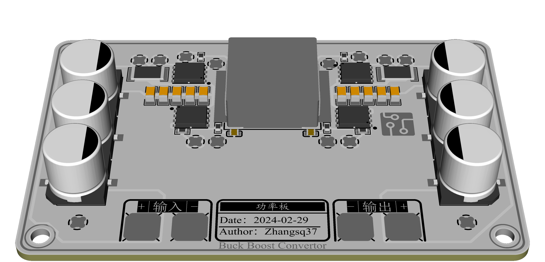
High-power automatic buck-boost module - SC8701
The power board and driver board are combined in a dual-board design with natural heat dissipation on the aluminum substrate, meeting the requirements of high-current operation.
1. Design Inspiration:
Due to data loss caused by an unexpected power outage, I conceived the idea of purchasing a UPS. Since most high-power UPSs on the market are AC220V, and 12V UPSs have pitifully small capacity and power, and use ternary lithium batteries unsuitable for long-term energy storage and with poor safety, I decided to design a high-power UPS based on lithium iron phosphate batteries, outputting DC12V. This project serves as an intermediate component of the UPS, with the hope of reuse in other projects.
Later, I realized that my need for high power was a misnomer:
my small host's peak power doesn't exceed 60W, and using a high-power UPS under low load conditions would be inefficient and take up too much circuit space; for
devices exceeding 300W, an AC UPS would be more suitable—
all of the above is redundant. However, since I had already researched and purchased the chips, there was no reason to give up halfway, hence this open-source project. 2. Introduction:
Both boards are 86mm*54mm in size, with 3mm rounded corners and a 1.6mm board thickness. This is the common size of an ID card or bank card.
(1) Power board
The power board needs to use an aluminum substrate. The high thermal conductivity of the aluminum substrate will evenly distribute the heat generated by the MOSFET during operation. It can be cooled by air cooling or wall cooling. The board has reserved 0603 NTC resistor positions, which can be used for temperature detection.
Components used:
Power inductor: 1770 power inductor, please determine the inductance value and saturation current according to the application scenario.
MOSFET: DFN5x6 package, note that Qg should not be too large (CJAC80SN10).
Current sensing resistor: 2512 sampling resistor, its resistance value needs to be modified together with the matching resistor (5mΩ).
MLCC: 1206 (50V, 10uF)
. Surface mount electrolytic capacitor: BD10 package, BD8 package (50V, 220uF) can be selected.
Binding post: 5mm*5mm surface mount binding post. Gate
resistor: 0603.
Screw hole: M3.
Note: The board-to-board connector is a 2mm PINGO probe, but since PINGO probes are indeed expensive, I recommend that you purchase a 2.54mm pitch round female connector. Cut off the injection molded part with diagonal pliers to get a usable connector, which can be male or female. (2) Driver Board:
The driver board is a double-layer board design with reserved slots for capacitors and inductors.
The driver board is not reversible, and all surface-mount components are on the same side. The driver board can be reversed to hide components.
Since the PWM regulation voltage range is [1/6, 1] times Vset, in order to expand the voltage coverage range, the SW pin can be used to control the switching of the MOSFET on and off to switch the range.
The NTC pin can be surface-mounted with a round busbar to continue upward.
The current limiting scheme can be selected by changing the resistor position (supporting up to one PWM regulation).

Components used:
Chip: SC8701, QFN4*4 package
; Resistors and capacitors: 0603
Schottky diode: SOD-323 package (1N5819)
; Pin header: 2*6 pin header, 2.54mm pitch.
N-MOS: SOT-23 package (AO3400) 3. Component parameter calculation reference:
Please refer to the chip datasheet for details:
Output voltage (PWM duty cycle 100%): FB reference voltage 1.22V
Output current: 1.22kV/R, (R is the current limiting setting resistor)
Bootstrap capacitor: 0.1uF
Input and output capacitors: 1uF
VCC gate drive capacitor: 1uF
Current sampling matching circuit: 47pF, resistor: 100000 * current sampling resistor value (500Ω@5mΩ)
For more details, please refer to the datasheet (attachment).
Note: The schematic does not specify the component parameters, so if SMT is required, please modify them to the required parameters. 4. Test video:
Constant voltage, constant current and short circuit test - Bilibili
Control function and high current test - Bilibili
5. Material cost reference:
The main material costs are as follows:
|Material|Quantity|Purchase price (single)|
|:--:|:--:|:--:|
|1770 power inductor|1|3.6|
|Power MOSFET|4|2.4|
|5x5 SMD Terminal Block|4|0.2|
|SC8701|1|2.96|
|1206 Capacitor|10|0.2|
|BD10 Capacitor|6|1.3|
|2512 Resistor|2|0.45|
Other material costs not exceeding 2 yuan, estimated cost (excluding PCB) not exceeding 30 yuan
SC8701.pdf
SouthChip-SC880X-NOTES.pdf
SC8701-CN.pdf
Control demo code.zip
Materials.md
PDF_High-Power Automatic Buck-Buck Module - SC8701.zip
Altium High Power Automatic Buck-Buck Module - SC8701.zip
PADS High Power Automatic Buck-Buck Module - SC8701.zip
BOM_High Power Automatic Buck-Buck Module-SC8701.xlsx
95633
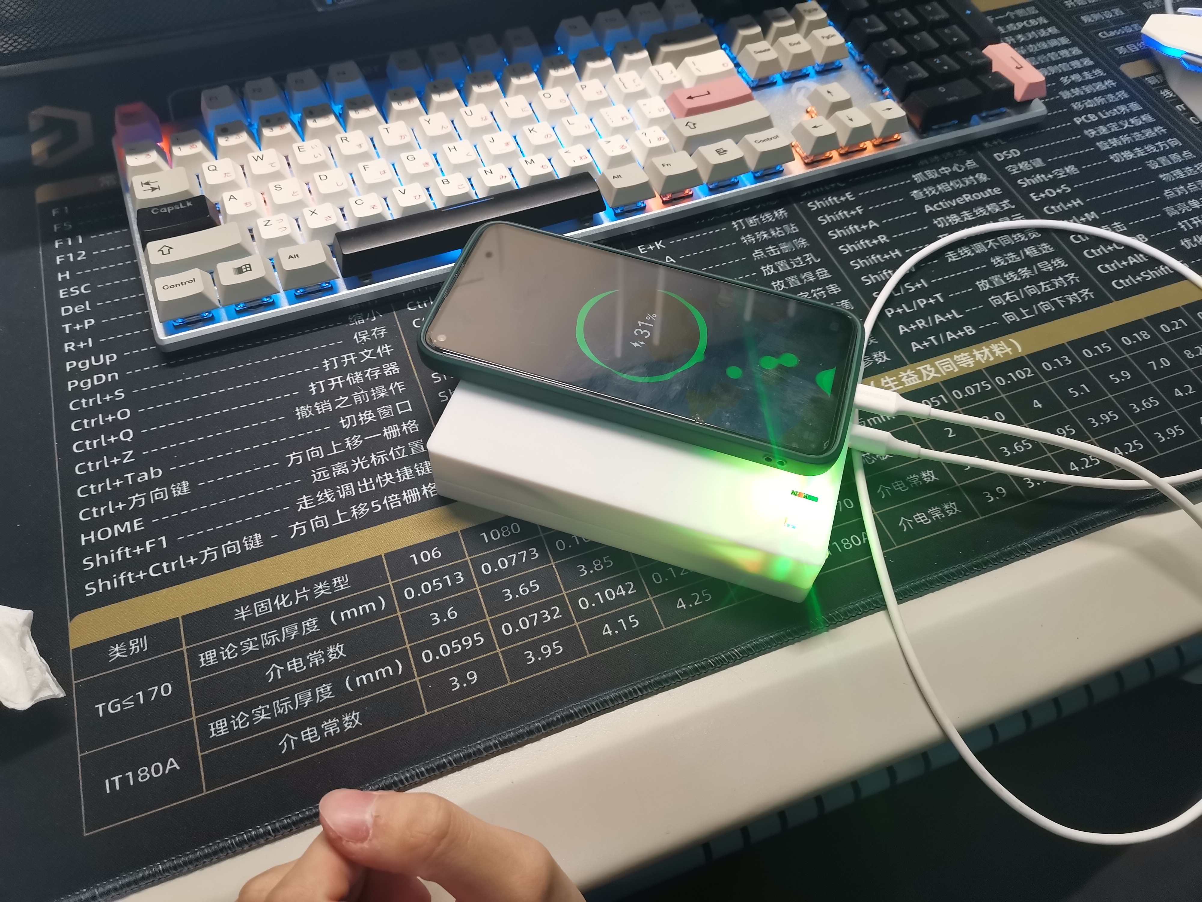
60W fast charging power bank
Homemade 60W (maximum) fast charging power bank based on IP5389
For details, please refer to the IP5389 manual.
Injoinic-IP5389.pdf
PDF_60W Fast Charging Power Bank.zip
Altium 60W Fast Charging Power Bank.zip
PADS 60W Fast Charging Power Bank.zip
BOM_60W Fast Charging Power Bank.xlsx
95635
#7th LCSC Electronics Design Contest# Voltage and Ammeter
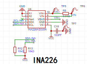
Type-C voltage and current meter based on HeZhou Air001 + INA226
The project originated from
my participation in the LCSC voltage and current meter training camp in 2022. Due to my internship at the time, the project progressed slowly. The verification failed before the camp ended, so I opted to postpone completion.
Later, I went on a business trip and completely suspended the project. When I resumed, the consumables I had previously purchased had disappeared. Work pressure further delayed the project.
Now that I've resigned and have more free time, I referenced projects on the LCSC Open Source Platform and ultimately adopted Heze's air001 and INA226 chips.
Selection Guide
: Type-C: 24-pin full-function Type-C
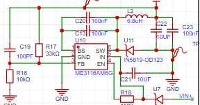
; DC-DC: ME3116 supports wide voltage input 4.75-40V;
MCU: Air001 (0.7 RMB)
; INA226: 36V, 16-bit, ultra-precision I2C output current/voltage/power monitor with alarm function.
Schematic Design Description
: Type-C:

INA226:
ME3116:
PCB Design Description :
Board thickness: 0.8mm;
Process: Default process;

Software Description:
To be improved
; Completed: Screen driver porting
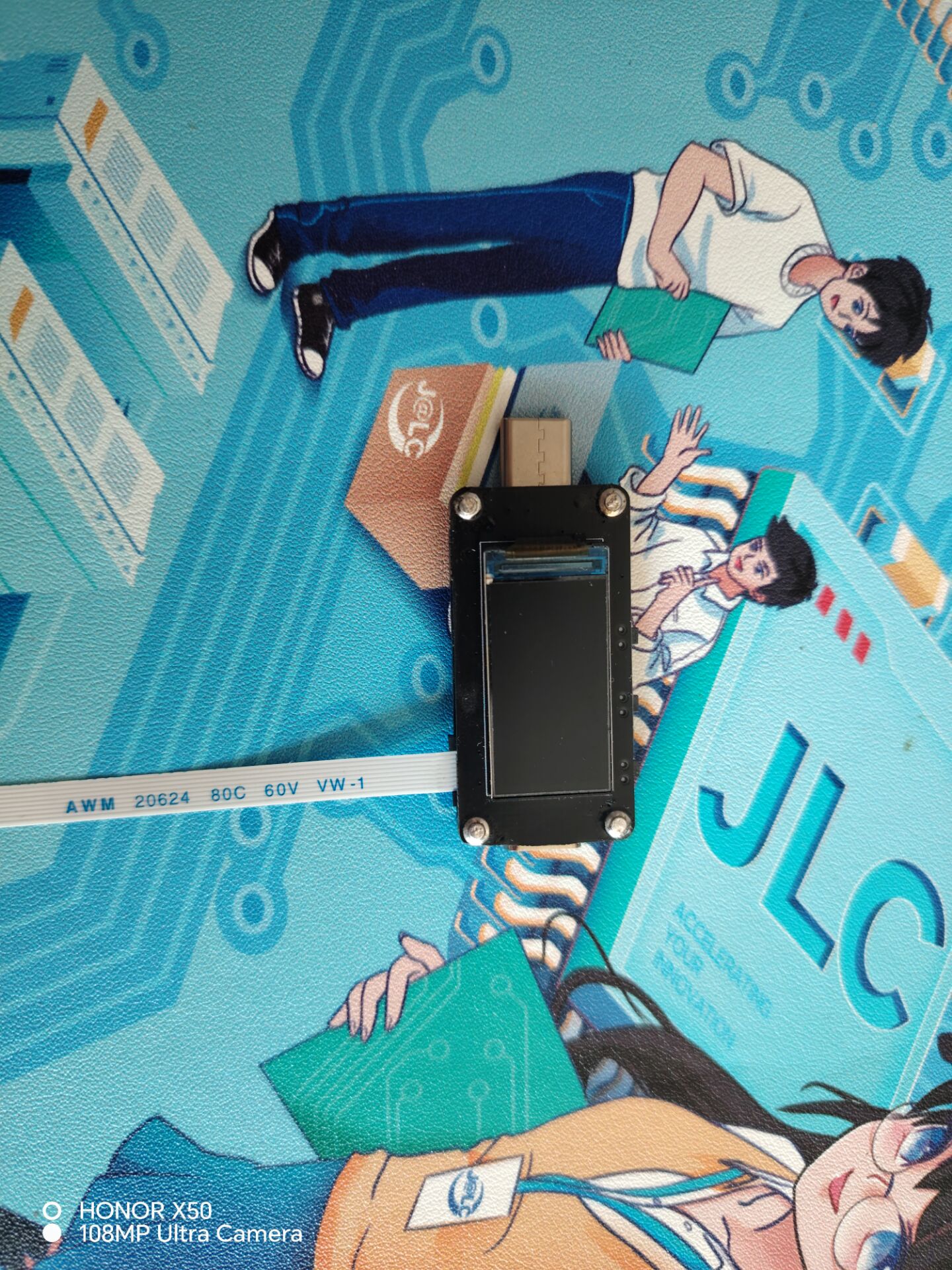
; Physical Demonstration Description:
Connection method: FPC flexible cable;
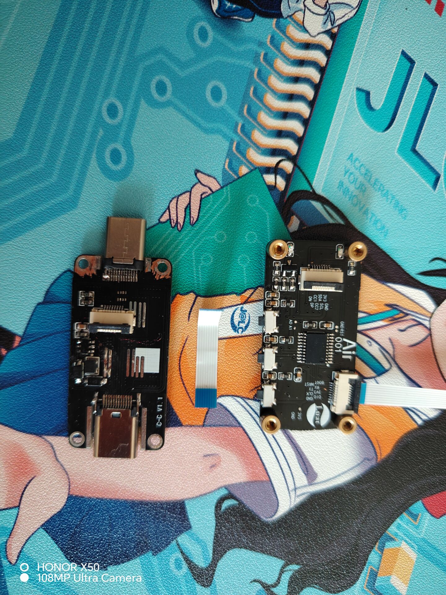
Fixing method: M.2 screw;
Programming: Reset/download circuit external/FPC flexible cable connection (programming interface to be changed later);

Physical Preview
Notes:
Board thickness 0.8/0.1mm
; Programming method is customized; Modifications are recommended; PCB design
software is not yet perfect, proceed with caution.
Project.uvprojx
PDF_#7th LCSC Electronics Design Contest# Voltage and Current Meters.zip
Altium_#7th LCSC Electronics Design Contest# Voltage and Current Meters.zip
PADS_#7th LCSC Electronics Design Contest# Voltage and Current Meters.zip
BOM_#7th LCSC Electronics Design Contest# Voltage and Current Meters.xlsx
95636
High-quality Bluetooth mini speaker
3D printed sealed Bluetooth speaker
This Bluetooth speaker features a 3D-printed shell, a CNC-machined aluminum alloy panel, a Pialix 2-inch full-range speaker, and currently uses an MH-M38 Bluetooth amplifier module and a lithium battery charging/discharging module. It's compact
and portable. Two 3D-printed panel sizes are provided for the HiVi B2S full-range speaker and the Pialix P830983 speaker, both of which deliver decent performance.
The speaker's shell, metal speaker panel, and PCB were all purchased using a free voucher provided by LCSC, so the cost only includes the speaker and Bluetooth amplifier board, making it worth trying.
petal_20240320_193444.mp4
PDF_High-quality Bluetooth speaker.zip
Altium High-Quality Bluetooth Speaker.zip
PADS_High-Quality Bluetooth Mini Speaker.zip
BOM_High-Quality Bluetooth Speaker.xlsx
95637
Star Flash
The StarShine development board has been verified and is ready for use.
This is a replica of a domestically manufactured StarShine development board, differing in size from the official original. It includes an additional serial port with level conversion. To communicate with a microprocessor, the UART_H0 port can be brought out.
PDF_StarShine.zip
Altium_Starlight.zip
PADS_StarShine.zip
BOM_Starlight.xlsx
95638
[2023 Electronic Design Contest] Intelligent Car Design
The complete hardware design for the intelligent car includes an independent DC-DC voltage regulator module, an STM32 minimum system board, and a car baseboard (which includes the DC-DC voltage regulator). It can be used simply by adding the car frame and motor.
Test code is attached.
Contact the author via QQ: 2456640595.
The design includes:
1. Independent DC-DC regulator module (capable of outputting 3.3V, 5V, and ADJ adjustable output)
2. Car main control board (onboard DC-DC regulator, 16-25V input, step-down to 5V and 8V)
3. STM32 minimum system board (same size as commonly available STM32 minimum system boards, can be directly replaced)
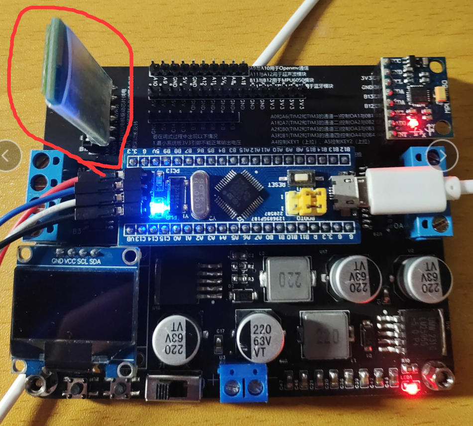
Please note: There was an error on the author's board, namely, the silkscreen of the Bluetooth module was reversed. It has now been corrected; simply plug in the Bluetooth module as shown in the picture.
If there is enough interest, a video tutorial will be considered on Bilibili .
The following will be updated:
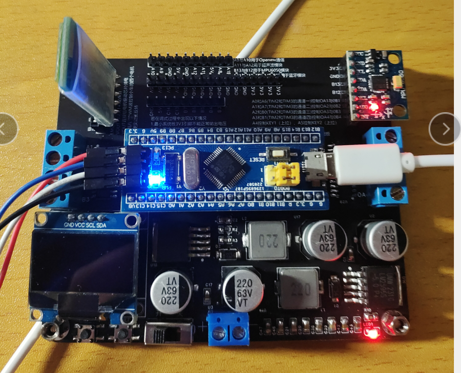
I. Soldering and testing of the car main control board
1. The effect after soldering and connecting the download and USB cables is shown below:
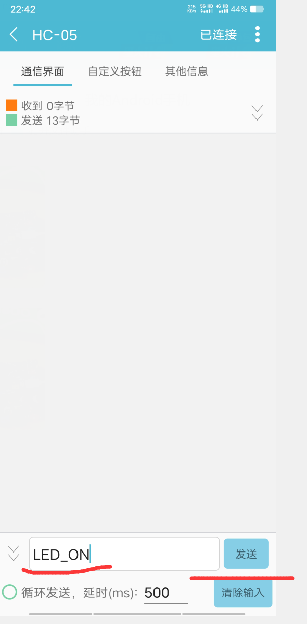
2. Test whether the car's Bluetooth module functions normally.
Expected experimental effect:
After the mobile phone sends the string "LED_OFF" through the Bluetooth assistant, the onboard LED of the STM32 minimum system board will turn off.
After sending the string "LED_ON", the onboard LED of the STM32 minimum system board lights up.
Test result:


3. Test whether the onboard OLED screen display function is normal
. After programming the code, the OLED screen displays "Hello_STM32".
Test result:

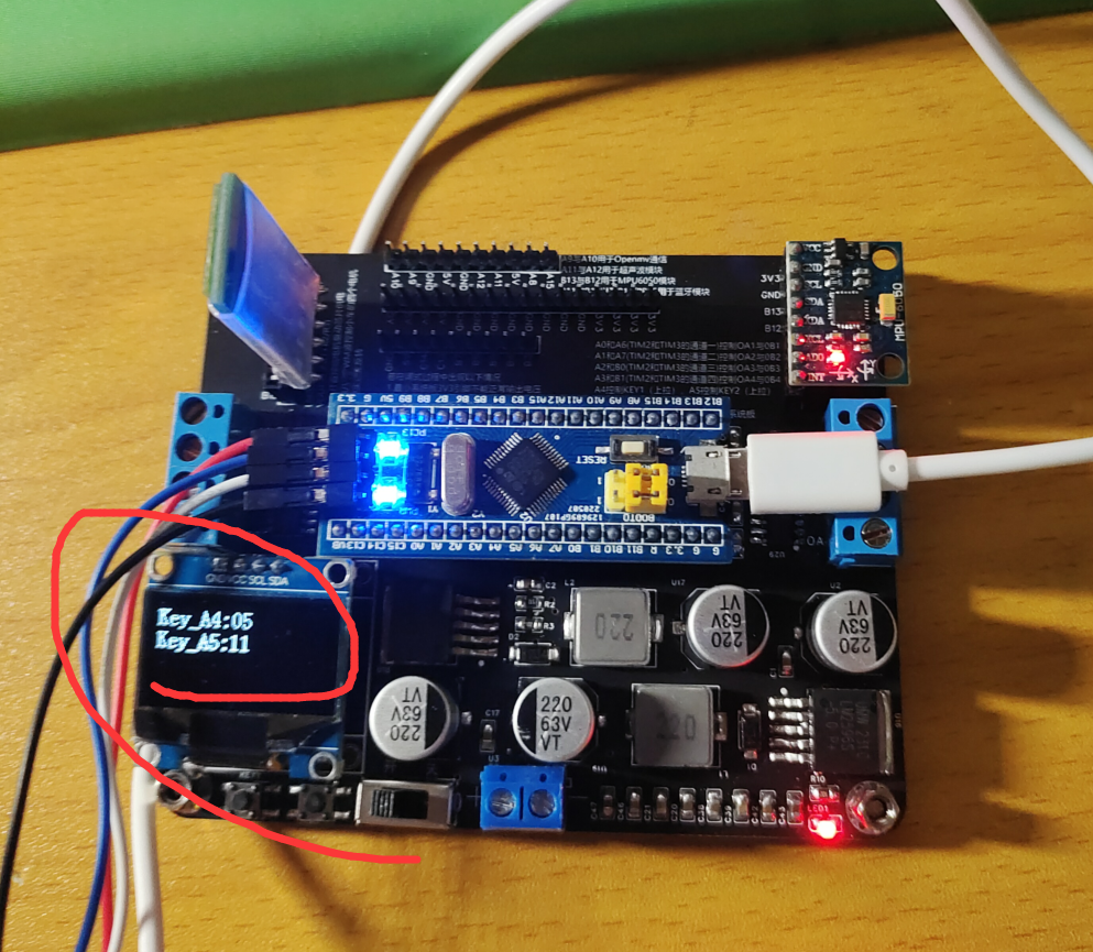
4. Test the onboard buttons
. After programming the code, the OLED screen displays the number of times each button is pressed.
Test result:
5. Test read the onboard MPU6050 data .
After programming the code, the OLED screen displays the MPU6050 data.
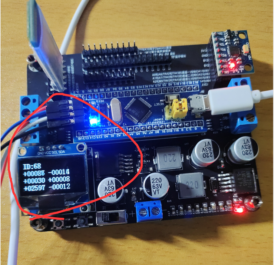
Note: Because the code does not perform any data filtering, the data is unstable.
6. Test read the onboard buzzer.
After programming the code, the buzzer sounds intermittently. (No demo images are provided here.)
II. Design of a Bluetooth-controlled car
III. Code design of a line-following car using a grayscale sensor
IV. Code design of a line-following car using OpenMV
V. Code design of Problem C from the 2022 National Electronic Design Contest
VI. Code design of Problem F from the 2021 National Electronic Design Contest
Declaration: Some code is taken from the code of Jiangsu University of Science and Technology on Bilibili, and the core code is taken from the Taobao store "Witch Development Board".
If there is any infringement, please contact me to delete it.
Test if the baseboard MPU6050 can read data normally.zip
Test whether the OLED screen display on the base plate is normal.zip
Test if the onboard buttons on the baseboard are functioning properly.zip
Test if the onboard buzzer of the baseboard is working properly.zip
Test baseboard Bluetooth communication with mobile APP.zip
PDF_【2023 Electronic Design Contest】Intelligent Car Design.zip
Altium_【2023 Electronic Design Contest】Intelligent Car Design for the Electronic Design Contest.zip
PADS_【2023 Electronic Design Contest】Intelligent Car Design for the Electronic Design Contest.zip
BOM_【2023 Electronic Design Contest】Intelligent Car Design for Electronic Design Contest.xlsx
95639
Expansion circuit (four-pin button)
Extended circuit schematics and PCBs
A simple intelligent information acquisition system circuit including a temperature sensor, a buzzer, and a display screen.
PDF_Extended Circuit (Four-Pin Button).zip
Altium_Extended Circuit (Four-Pin Button).zip
PADS_Extended Circuit (Four-Pin Button).zip
BOM_Extended Circuit (Four-Pin Button).xlsx
95641
STM32F103C8T6 perforated board
Used for debugging STM32 interfaces, electronic design, and DIY projects.
This expansion board integrates a wealth of interfaces, making it easy for developers to create their own functionalities!
PDF_STM32F103C8T6 perforated board.zip
Altium_STM32F103C8T6 perforated board.zip
PADS_STM32F103C8T6 perforated board.zip
BOM_STM32F103C8T6 perforated board.xlsx
95642
electronic


 京公网安备 11010802033920号

 CAT25C03GLETE13


