The shape of the circuit layer pattern was modified

, the board size was adjusted, and the edges were chamfered.

PDF_Van Gogh Starry Night PCB Optimized Version.zip
Altium_Van Gogh Starry Night PCB Optimized Version.zip
PADS_Van Gogh Starry Night PCB Optimized Version.zip
95654
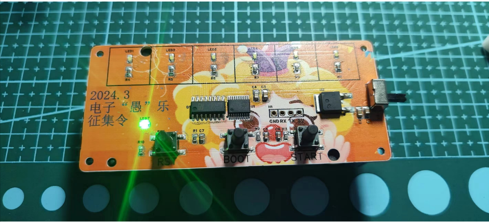
Electronic dice
An electronic die made using the air001 chip.
This is an electronic dice made using the air001 chip, intended as an alternative to physical dice for entertainment.
Project features:
1. Convenience: Compared to traditional dice, electronic dice are more portable, easier to carry and use, and less likely to be lost. 2. Randomness: It can simulate the randomness of real dice through an internal random number generator. 3. Programmability: Electronic dice can be programmed to implement specific rules or game modes. 4. Visualization: Simulates the display of results from real dice, providing a clear and intuitive experience. 5. Fairness and impartiality: Through programming, the probability of each result is equal, preventing cheating. 6. Noise-free: Physical dice are quite noisy and can easily disturb those around them; electronic dice are noise-free and can be used without disturbing others.
Due to an initial oversight, the reset and start buttons were reversed on the prototype; this has been corrected.
Using black 3D printing material would likely yield better results.


Shell.STL
Demo.mp4
Simple Code.zip
PDF_Electronic Dice.zip
Altium_electronic dice.zip
PADS_Electronic Dice.zip
BOM_Electronic Dice.xlsx
95655
MediaTek MT7628 router
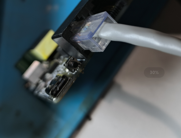
This is a 100Mbps router based on the MediaTek MT7628, supporting PoE power supply. It features isolated PoE power input, supports the IEEE 802.3af protocol, and can be converted into a 100Mbps access point panel.

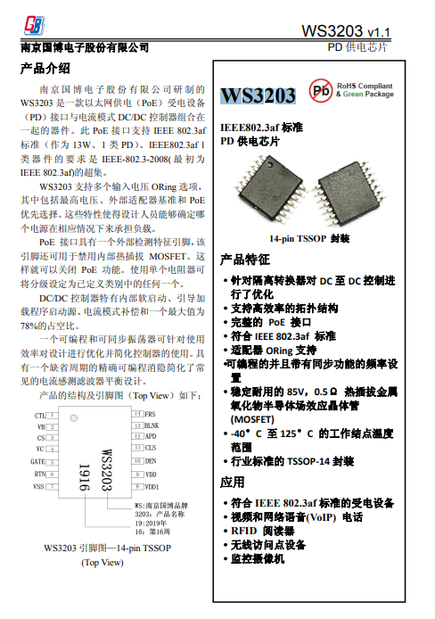
This solution uses the MediaTek MT7628 chip as the processor, and the PoE chip selected is the Nanjing Guobo WS3203
open source protocol: CC-BY-NC-SA3.0.
Configuration:
MT7628 main controller,
DDR2-128M memory
, 32MB FLASH storage,
WAN supports PoE power reception,
PoE protocol: IEEE 802.3af,
the main controller uses the E103-W20 module (MT7628 main controller)
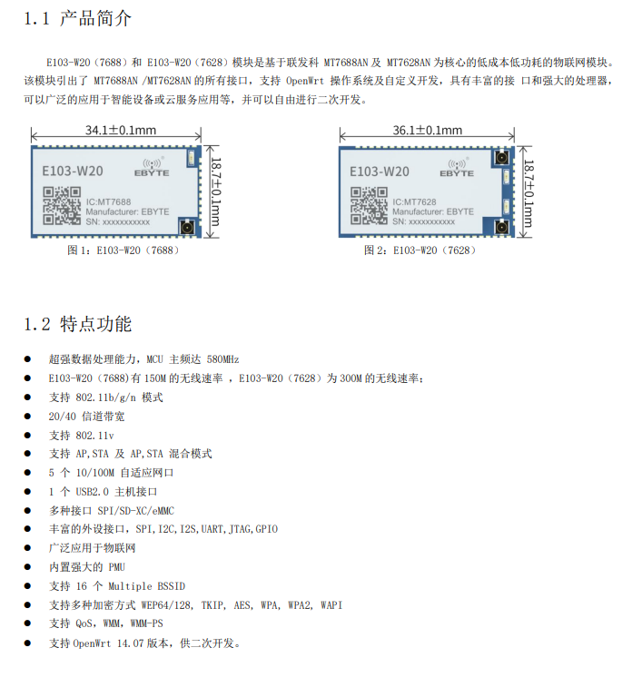
, and the PoE isolated power controller is the Nanjing Guobo WS3203.
Note: The initial design considered adding a USB-C port for power supply, using 48V for fast charging (PD3.1 protocol), but in actual testing, the regular USB-C port cannot use 48V, and hot-swapping will cause arcing and burn the interface. I've seen 48V solutions on the market, but they might be using custom USB-C
connectors that arced during cable disconnection
, causing issues with the PoE power supply handshake process (which is similar to the PD protocol).

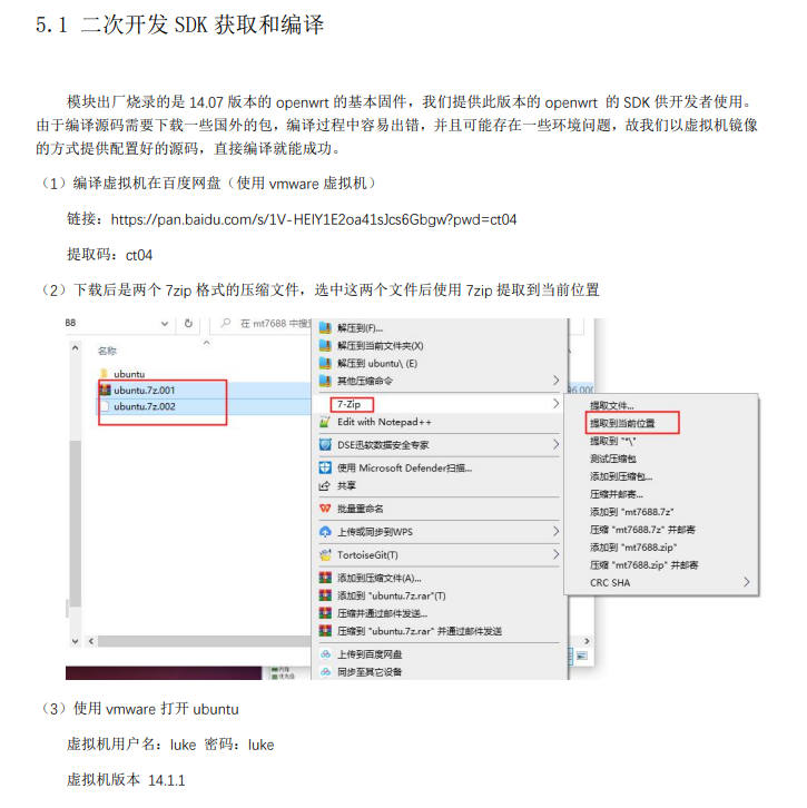
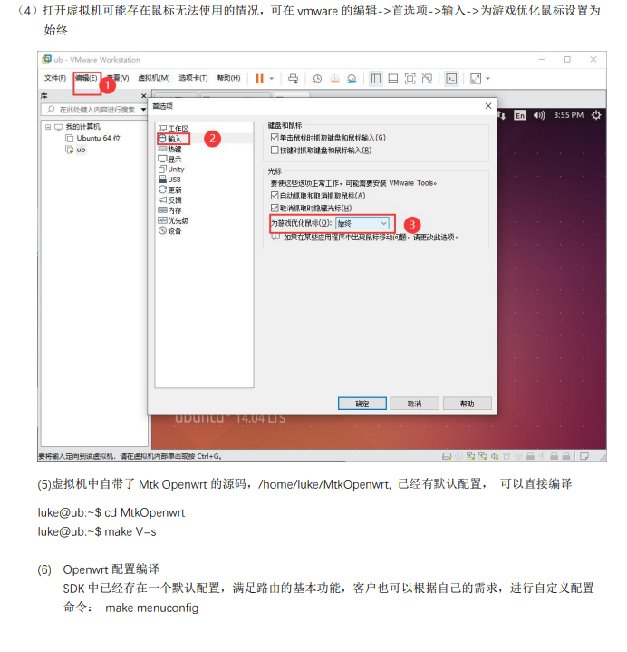
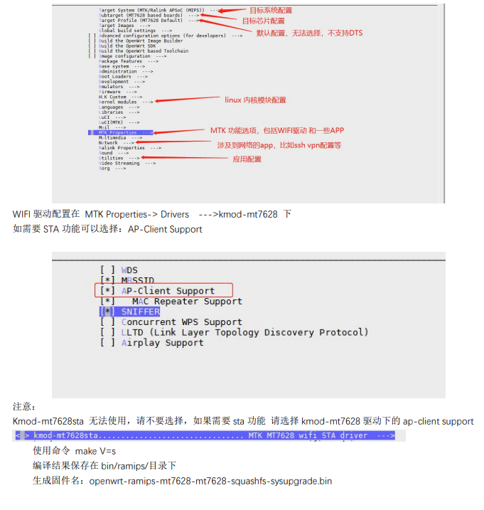
The E103-W20 module comes pre-installed with OpenWRT 14.07 firmware. For secondary development tutorials, please refer to the E103-W20 module datasheet. (
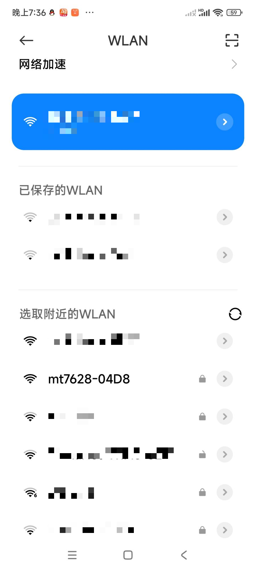
Mobile phone recognition of the E103-W20 module's Wi-Fi
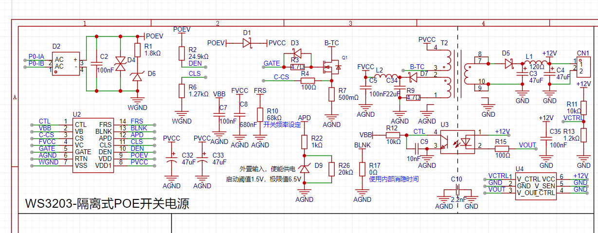
PoE switching power supply circuit.)
VID_20240304_195712_1.mp4
breed-mt7688-reset38.bin
PDF_MediaTek MT7628 Router.zip
Altium_MediaTek MT7628 router.zip
PADS_MediaTek MT7628 Router.zip
BOM_MediaTek MT7628 Router.xlsx
95656
A Simple Digital Oscilloscope Based on STM32
A simple STM32-based oscilloscope for detecting and displaying waveforms, and also capable of outputting PWM square waves with adjustable frequency and duty cycle.
A digital oscilloscope is an instrument used to display electrical signal waveforms. It mainly consists of analog front-end processing circuits, microcontroller circuits, power supply circuits, control circuits, trigger circuits, calibration circuits, and other circuits.
This training camp uses a GD32 as the main controller (fully compatible with STM32F103C8T6) for DAC sampling and output of signals.
1. The power module
uses a 3.7V lithium battery and a Type-C port for power supply. A power switching circuit switches between Type-C and lithium battery power. The voltage is then boosted by a PW5100 chip before powering other components.


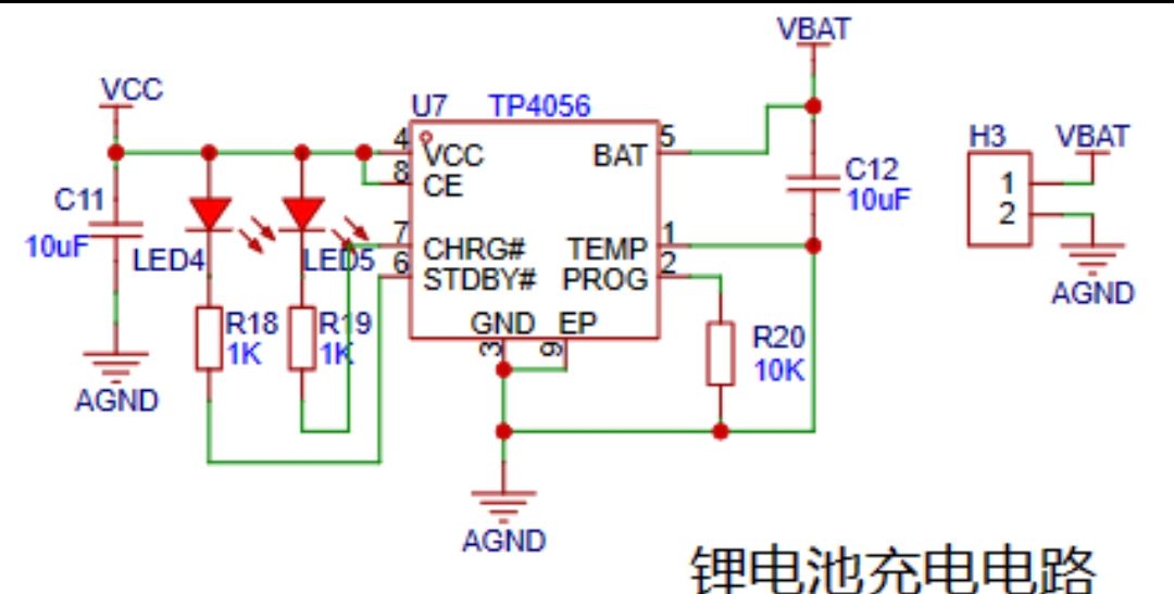
The lithium battery charging circuit uses a TP4056 to charge the battery. Two indicator lights monitor the battery level: a green light indicates charging is complete, and a red light indicates charging is in progress. In addition to the power input circuit,
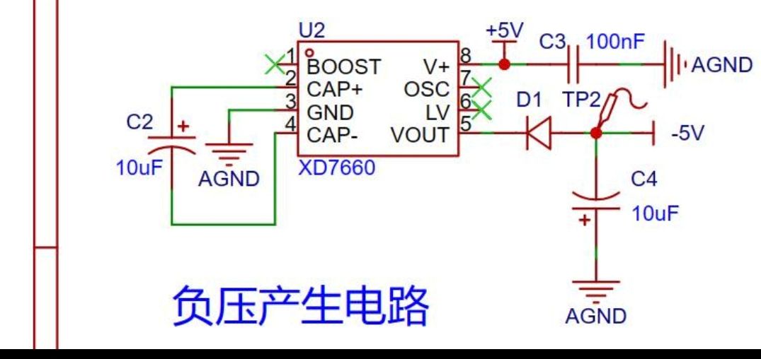
the negative voltage generation circuit
uses the XD7660 negative voltage generator to obtain a negative voltage to ensure the operational amplifier's performance in measuring negative voltages. This chip has a simple external circuit, requiring only two capacitors and a diode to operate. Theoretically, with an input voltage of +5V, it can also output a -5V voltage. Due to the chip's internal voltage drop and conversion efficiency, the actual measured negative voltage is approximately -4.3V, which still meets the operational amplifier's requirements.
2. The analog front-end processing circuit
includes an input AC/DC coupling switching circuit, an input signal attenuation circuit, and a signal conditioning circuit.
AC/DC coupling switching circuit: A 100nF capacitor is used to block the DC component. The higher the frequency, the smaller the capacitor should be; 100nF is sufficient here. For capacitor selection, please refer to relevant documentation.
Signal attenuation circuit: When measuring high voltage, the board cannot withstand it, so voltage attenuation is necessary. Here, the voltage is attenuated by 1/50. This allows us to calculate that the low-voltage range can measure -1.6~+5V, and the high-voltage range can measure -80V~+250V. Since there is no protection, it's best to avoid measuring high voltage for safety reasons. You can also change the attenuation factor by replacing the resistor.
Signal conditioning circuit: This involves analog electronics knowledge and can be analyzed using the concepts of "virtual short" and "virtual open". A voltage follower (impedance matching) and a proportional amplifier circuit are added after this, resulting in Vo = (5-Vin)/2.

3. Comparator frequency measurement circuit:
The ADC input signal is compared with the input signal through a hysteresis comparator to achieve frequency measurement.
To enhance the circuit's anti-interference capability, positive feedback is introduced on top of the single-limit comparator to ensure signal stability within a certain range. After passing through the hysteresis comparator circuit, a square wave signal is output. The period of the input waveform is calculated using the microcontroller's timer capture function.

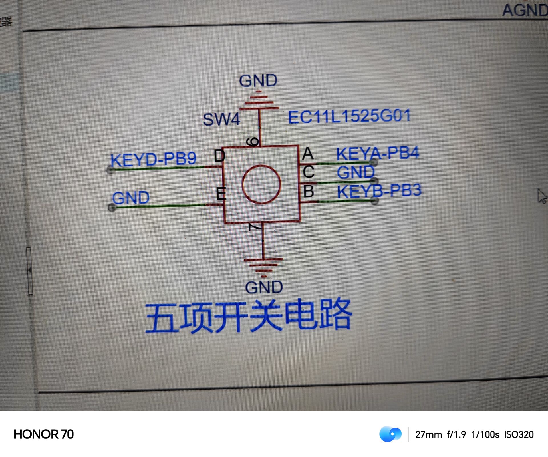
4. Rotary Encoder Circuit: A
rotary encoder is a special type of button. The EC11 rotary encoder used in this project has five pins. Pins D and E are similar to ordinary button pins; they conduct when pressed and disconnect when released. The remaining three pins, A, B, and C, are used to detect the rotation direction of the knob. Pin C is the common terminal and can be directly grounded.
During rotary encoder operation, there is a phase difference between the A and B signal pins. That is, a change in the signal on one pin occurs before the signal on the other pin changes, meaning the two pins do not change simultaneously. By detecting which pin changes first, the clockwise or counterclockwise rotation function can be determined.
The rest of the circuit is relatively simple and will not be described in detail here.
Next, let's look at the actual finished product .

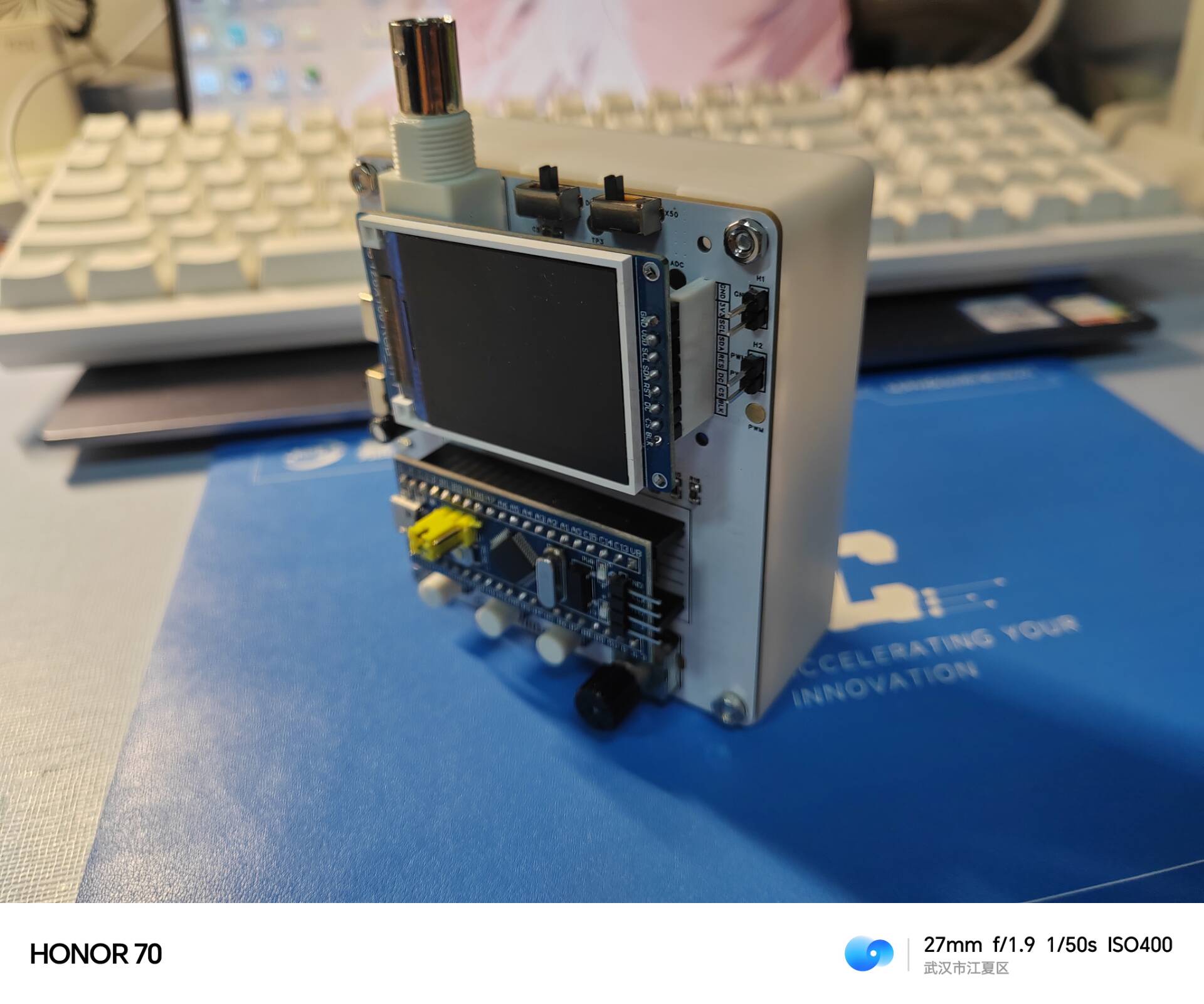

After measurement, the square wave bandwidth can reach 30~50KHz, making it a good measurement tool.
You can view the effect through a video.
The GD32 and STM32 source code and HEX files, as well as the BIN file, are all included below. If the GD32 software crashes when burning the HEX file, try using the BIN file instead. STM32 serial programming can be done using FLYMCU.
Simple Oscilloscope STM32 Version (1).rar
CH340 driver.zip
FlyMcu.exe
Oscilloscope factory firmware.bin
Simple digital oscilloscope factory firmware.hex
QQ Video 20240319233156.mp4
PDF_Simple Digital Oscilloscope Based on STM32.zip
Altium_Simple Digital Oscilloscope Based on STM32.zip
PADS_Simple Digital Oscilloscope Based on STM32.zip
BOM_Simple Digital Oscilloscope Based on STM32.xlsx
95657
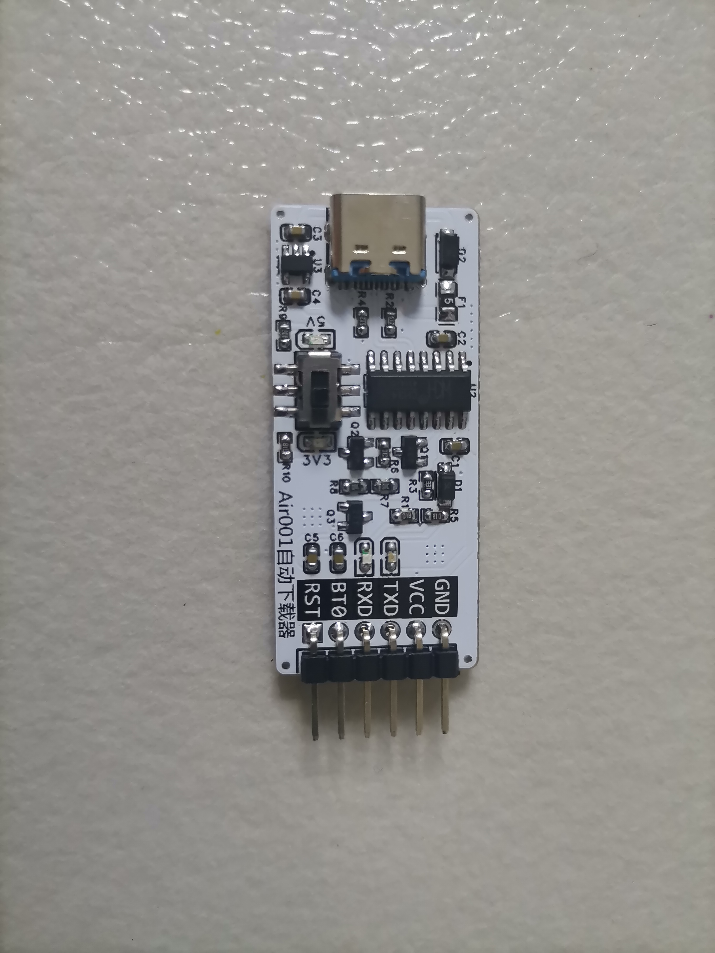
Air001 Auto Downloader - Switchable Power Version
A tool specifically designed for automatic serial port downloading of the air001 microcontroller, supporting 3.3V and 5V.
I referenced Walkline's solution on the open-source platform (https://oshwhub.com/walkline/air001-auto-download-tool)
and modified it to have a switchable power supply, making it convenient for different voltage scenarios.
PDF_Air001 Auto Downloader - Power Switchable Version.zip
Altium_Air001 Auto Downloader - Power Switchable Version.zip
PADS_Air001 Auto Downloader - Power Switchable Version.zip
BOM_Air001 Auto Downloader - Power Switchable Version.xlsx
95658
LCSC Taishanpai Voice Recognition Expansion Board
Voice recognition expansion board for LCSC Taishanpai
The LCSC Taishanpai voice recognition expansion board, based on the Haohaodada ASRPRO4M chip, can be graphically programmed using Tianwen Block software, allowing for quick and easy setup without prior learning.
Please use Tianwen Block for programming, which can be downloaded from https://haohaodada.com/new/resource.php.
Select ASRPRO for the motherboard/device, as shown in the image below.

Then select the example program and
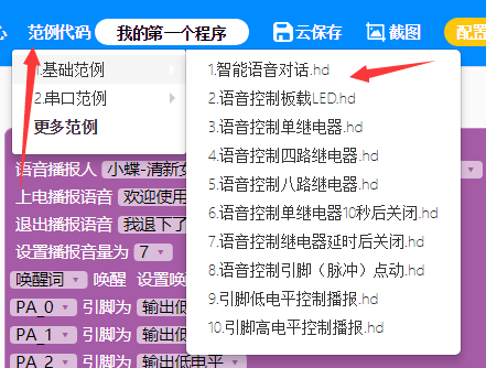
click "compile and download." Note that you should immediately unplug the USB cable after clicking "compile and download." Then select the ASRPRO-4M option, click "burn," and wait for the burning process to complete.

Note: This uses the example program. If you have modified it or are not using the example program, you need to generate a model before downloading.

This step takes 1-3 minutes, requires a stable internet connection, and registration/login.
Now you can enjoy playing with it!
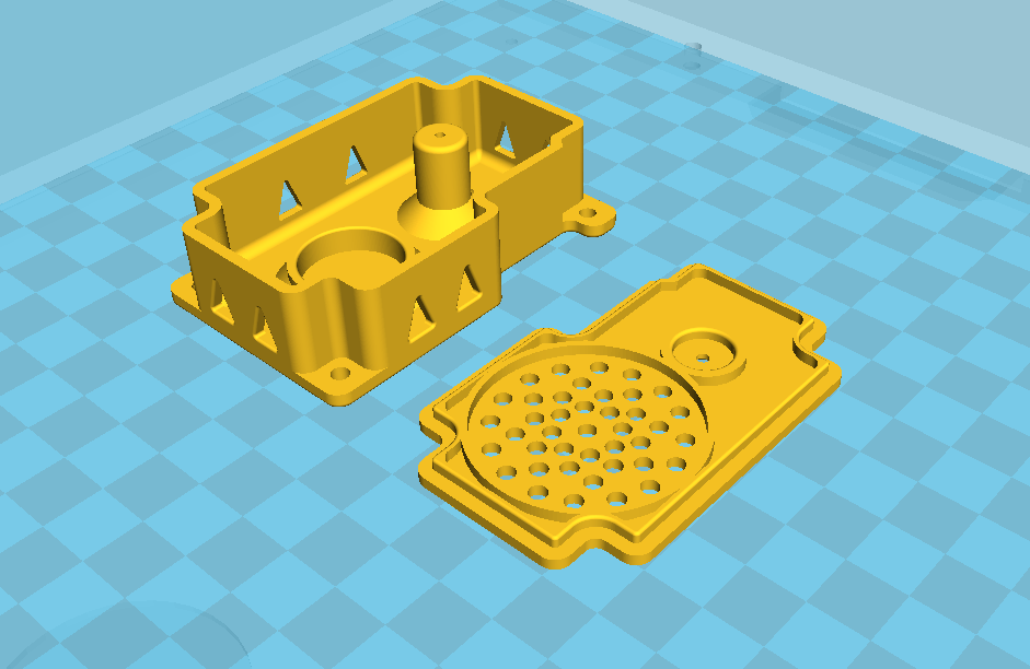
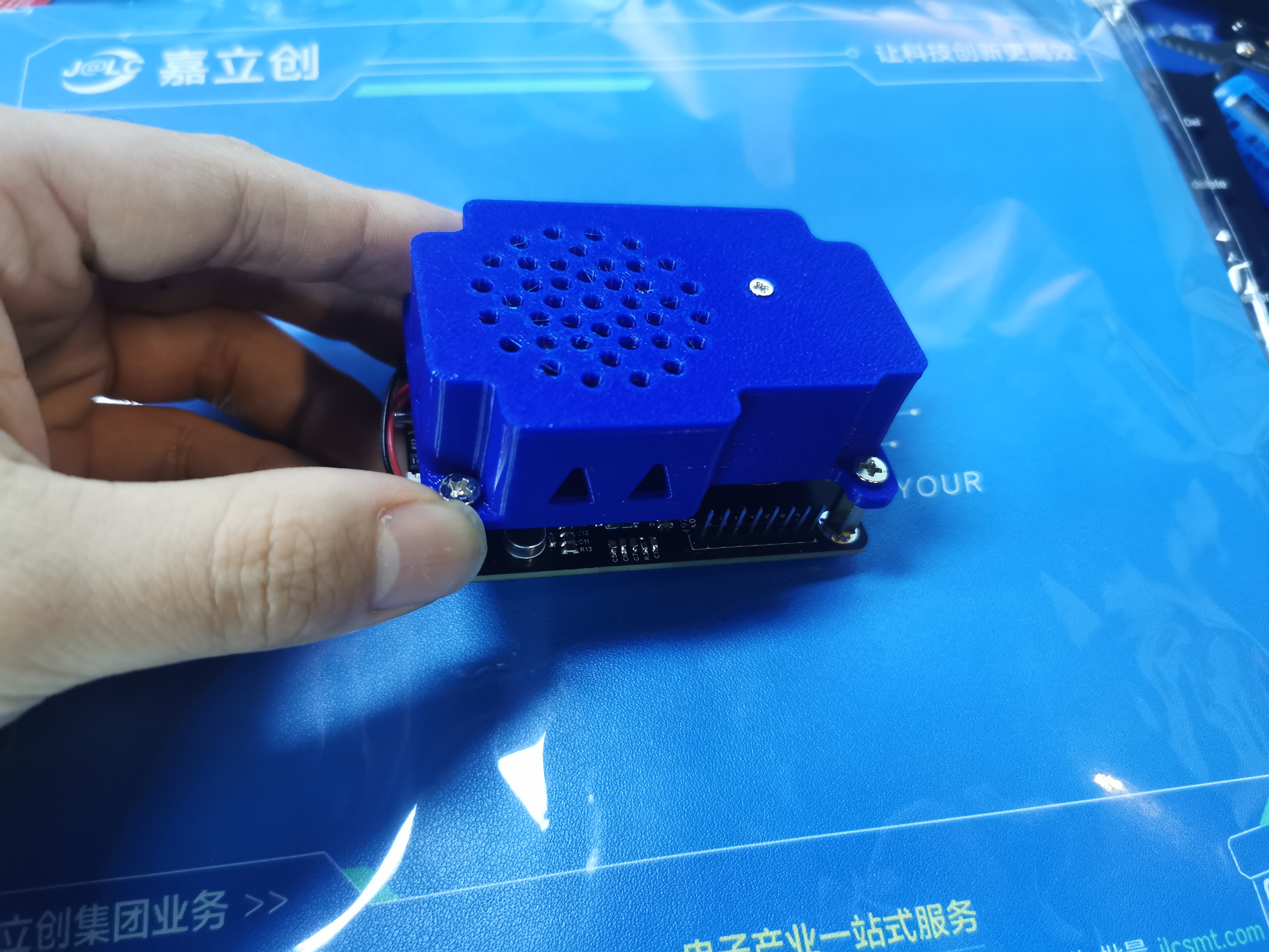
Of course, if you're interested, you can join the group 433214533 to discuss and play together. Mention "LCSC Taishanpai voice recognition" in your message. A 3D-printed speaker cavity shell was added
on March 19, 2024 ; see attachment.
The previous PCB speaker had a low power output, and it distorted at high volumes, so I replaced it with a larger one. The link to the speaker I'm using is here:
[Taobao] https://m.tb.cn/h.5C2s731exol1DvW?tk=W4FMWMScnSr ZH4920 "High-power speaker 36/40MM/3070/4070/3-inch 77MM speaker 4 ohms/8 ohms 2 watts/3 watts/5 watts" Click the link to open it directly, or search for it on Taobao and
select the first result

. The model looks roughly like this:
1b42c760eba6226868185922a5216020.mp4
Horn cavity model.rar
PDF_LCSC Taishanpai Speech Recognition Extension Board.zip
Altium_LCSC Taishanpai Speech Recognition Expansion Board.zip
PADS_LCSC Taishanpai Voice Recognition Expansion Board.zip
BOM_LCSC Taishanpai Voice Recognition Expansion Board.xlsx
95659
51 Minimum System Board
51 Minimum System Board
A compact and low-cost 51 minimum system board based on the STC89C52RC chip.
1d925673e252369767e3753ccdb75e88.jpg
WeChat image_20240318192705.jpg
PDF_51 Minimal System Board.zip
Altium_51 Minimal System Board.zip
PADS_51 Minimum System Board.zip
BOM_51 Minimum System Board.xlsx
95660
LCSC ESP32S3R8N8 Expansion Board V1.0
This expansion board is specifically designed for the LCSC ESP32S3 development board and includes features such as USB and lithium battery switching, battery charging, a 0.96-inch OLED screen, stepper motor driver, tri-color LED, digital display, temperature and humidity sensor, photosensitive sensor, rotary encoder, EEPROM, and infrared functionality.
This expansion board is specifically designed for the LCSC ESP32S3 development board and includes features such as USB and lithium battery switching, battery charging, a 0.96-inch OLED screen, stepper motor driver, tri-color LED, digital display, temperature and humidity sensor, photosensitive sensor, rotary encoder, EEPROM, and infrared functionality. The video demonstrates the software power-on/off function, OLED display, and photoresistor ADC voltage reading.

ESP32S3show.mp4
PDF_LCSC ESP32S3R8N8 Expansion Board V1.0.zip
Altium_LCSC ESP32S3R8N8 Expansion Board V1.0.zip
PADS_LCSC ESP32S3R8N8 Expansion Board V1.0.zip
BOM_LCSC ESP32S3R8N8 Expansion Board V1.0.xlsx
95662
FSBox
Speakers that can display the spectrum
The audio data transmitted via Bluetooth is played through an external audio IC, and the audio data is simultaneously subjected to FFT to cut the spectrum and display it on the screen.
f56eb57b8a8b5b51a5f59b912e1d68cb.mp4
614e1746b8a27ebe18e4061010130409.mp4
matrix_led.7z
CAD.7z
PDF_FSBox.zip
Altium_FSBox.zip
PADS_FSBox.zip
95663
Split keyboard almond_cake (no lights)
Based on the RP2040 Pico development board, this small-size, 30% layout split keyboard uses QMK+VIAL and is available with a free prototyping voucher.
The introduction
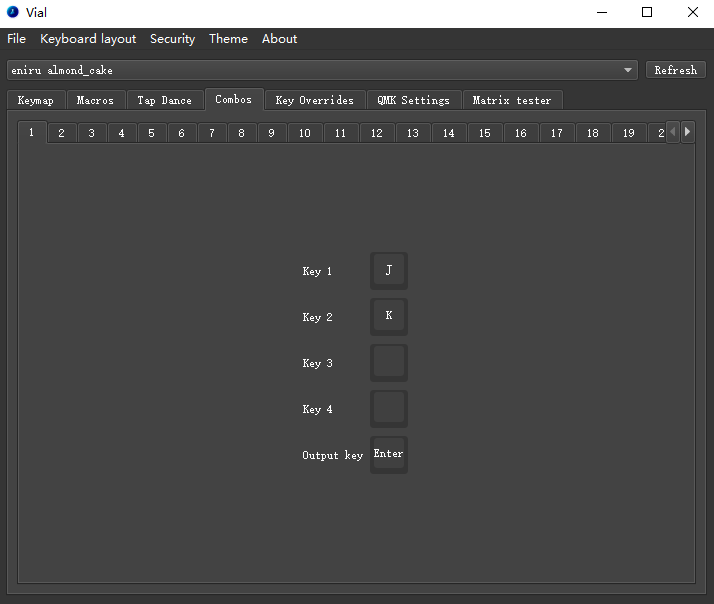
is a standard brief, but there's not much to say. I used the Vial because it's easy to modify the tap dance and combo keys .
Regarding the layout,
most 30% layouts look similar, basically the QAZ layout. With the addition of tap dance and combo keys, it's perfectly adequate for typing, and the feel isn't too bad.
However, you should think carefully before using it for gaming. I can at least use it for a full-star Abyss run. To save money, I still used the Pico
controller , but the Pico has effectively increased in price. Currently, I'm working on a version using the 52840 chip, a Bluetooth version , and a version with lighting later, but it's just an ambient light; I'm still evaluating whether to place it on the front or side . I didn't draw the outer shell, only the base plate; it's just screws and nuts tightened. Due to the development board... Place it on the back, and you need to tilt the keyboard. You need to put some height-increasing pads on it. I used the anti-collision pads that I posted before. I will put the link in the attachment. You can choose a cheaper one to buy depending on the situation. However, the minimum height is 8mm. Please note that I have prepared two positioning plates. Generally speaking, it is difficult to use the free coupon for the positioning plate. You can use either one depending on the situation. I used a smaller positioning plate for the homepage picture. Of course, DXF will also be provided in the attachment. Other parts (1) This time, you don't need to use color silk screen printing. You can't use color silk screen printing if you want to use the free coupon. (2) Each keyboard has a five-way switch, but I couldn't find a suitable switch cap for it. It's practically useless. So you don't have to solder it when you're using it yourself. I wanted to install the TrackPoint, but unfortunately, I can't use the TrackPoint when running QMK on my RP2040. It throws an error when I compile. (3) To fit the development board, all the switches are rotated 90° or 270°. This may cause some keycaps or switches to get stuck. If this happens, please replace it or just don't use this keyboard. (4) I didn't use low-profile switches this time. I plan to switch to the ZMK solution and then use low-profile switches. One reason is that low-profile switches are really expensive. (5) The keyboard firmware inexplicably misses burning a few keys. The specific reason is unknown. I will try to fix it. (6) As with previous projects, the headphone cable must be four-pole because full-duplex is used. (7) I didn't add RGB because the entire axis rotates 90°, which would make the position of the axis lights look strange and unsightly. Therefore, I didn't add axis light support. Instead, I added soldered axis holes, although it's only for MX axes.


Some material purchase links, for reference only.xlsx
almond_cake.rar
almond_cake universal positioning plate_universal base plate.dxf
almond_cake_vial.uf2
PDF_Almond Cake Split Keyboard (No Lights Version).zip
Altium split keyboard almond cake (no lights) .zip
PADS_Split Keyboard_almond_cake No Light Version.zip
BOM_Almond Cake Split Keyboard (No Lights) xlsx
95664
electronic


 京公网安备 11010802033920号

 MCR18EZHF4220


