The principle behind
OpenMV's official screens is that
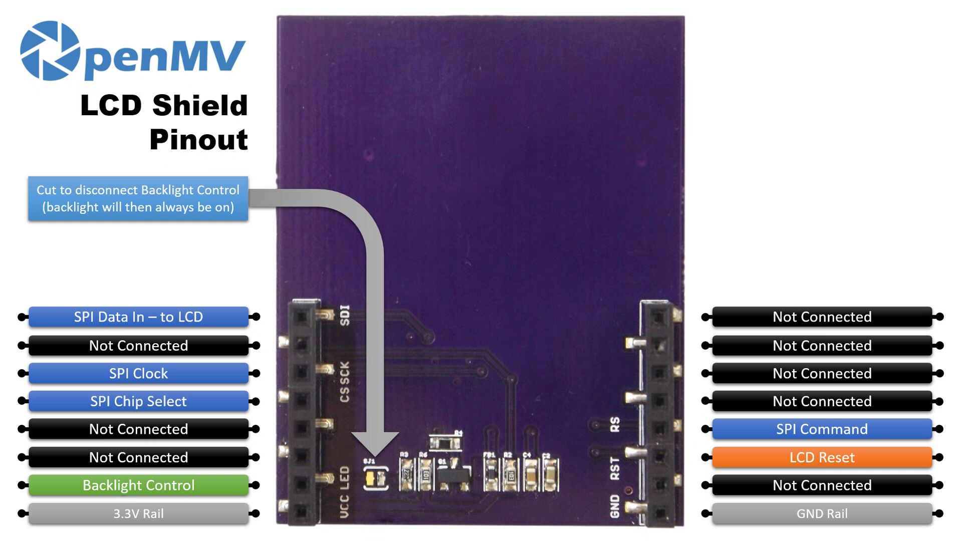
most 1.8-inch screens online

are SPI screens, which can light up the screen instantly.
However, this doesn't work for all screens. The author used a Hezhou 1.8-inch screen
and the effect was...

PDF_OpenMV LCD Adapter Board.zip
Altium_OpenMV LCD Adapter Board.zip
PADS_OpenMV LCD Adapter Board.zip
BOM_OpenMV LCD Adapter Board.xlsx
95703
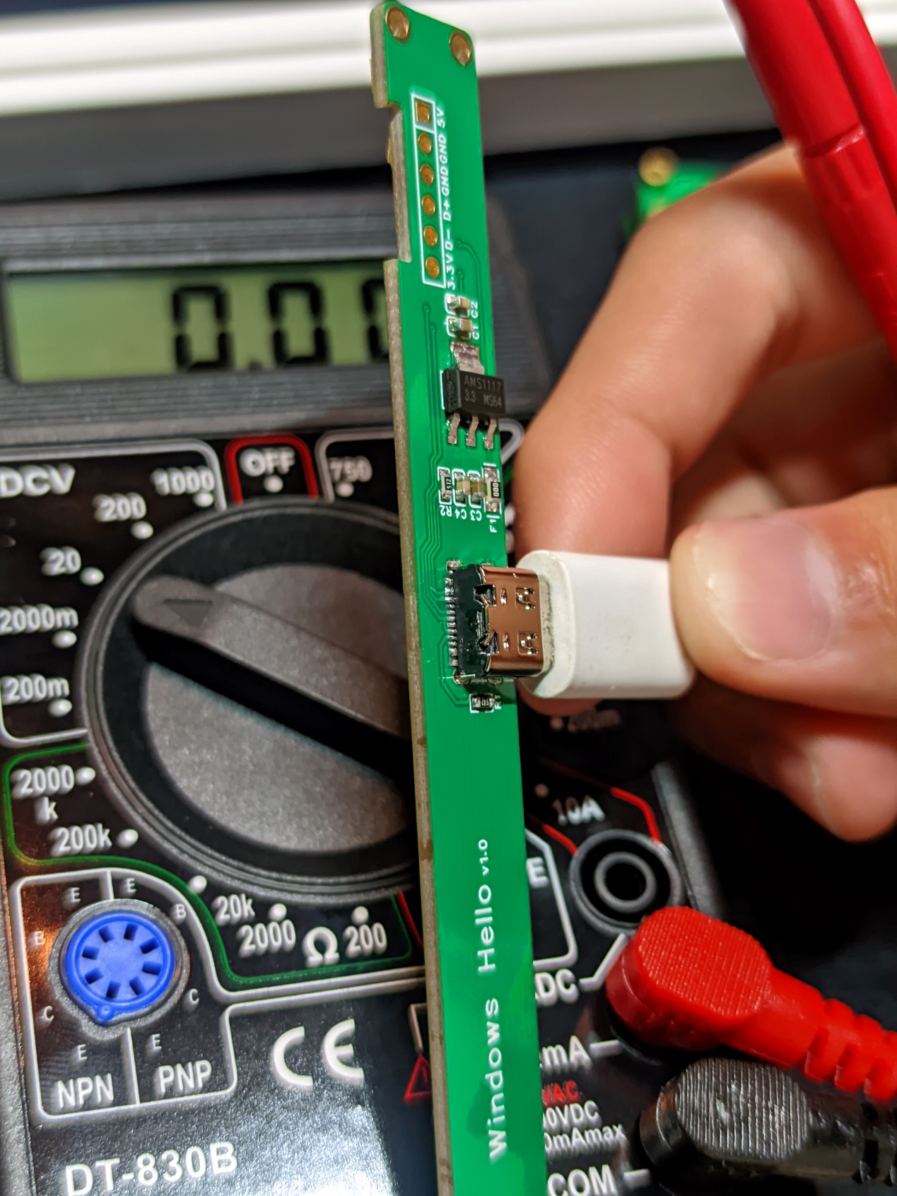
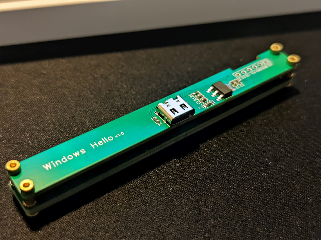
Windows hello module
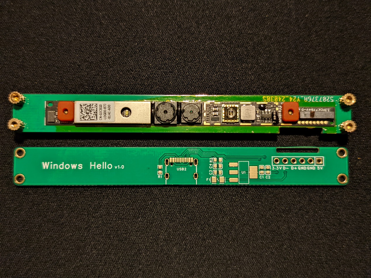
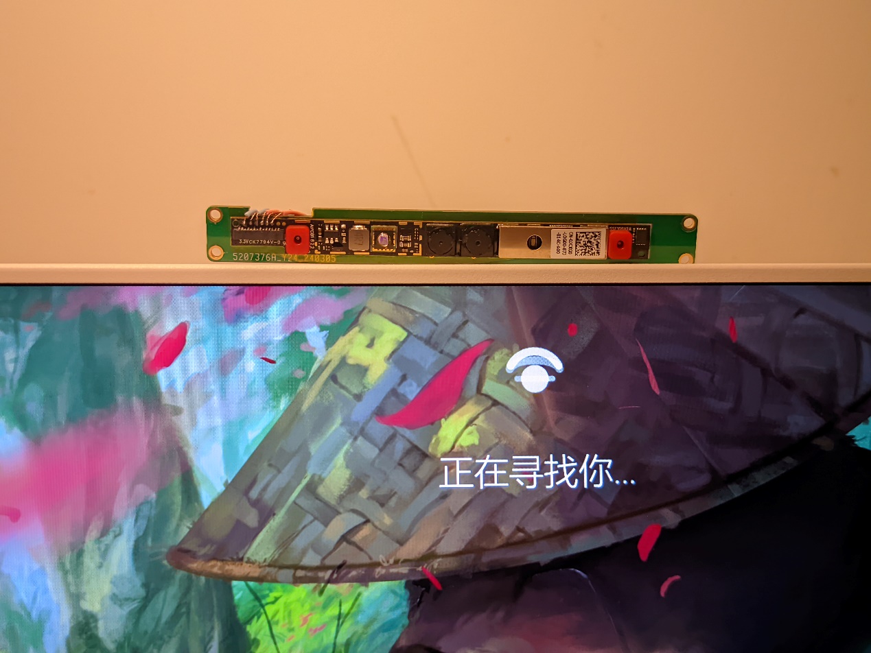
The project uses the 0JCXG0 module to enable Windows Hello unlocking on desktop computers.
I saw online that the 0JCXG0 module can enable Windows Hello face recognition on desktop computers, just like on laptops. So I looked it up a bit from some experts and designed my own board to make face recognition work on my ITX system (lol). Without further ado, let's get straight to the point:
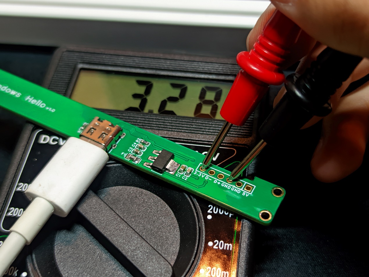
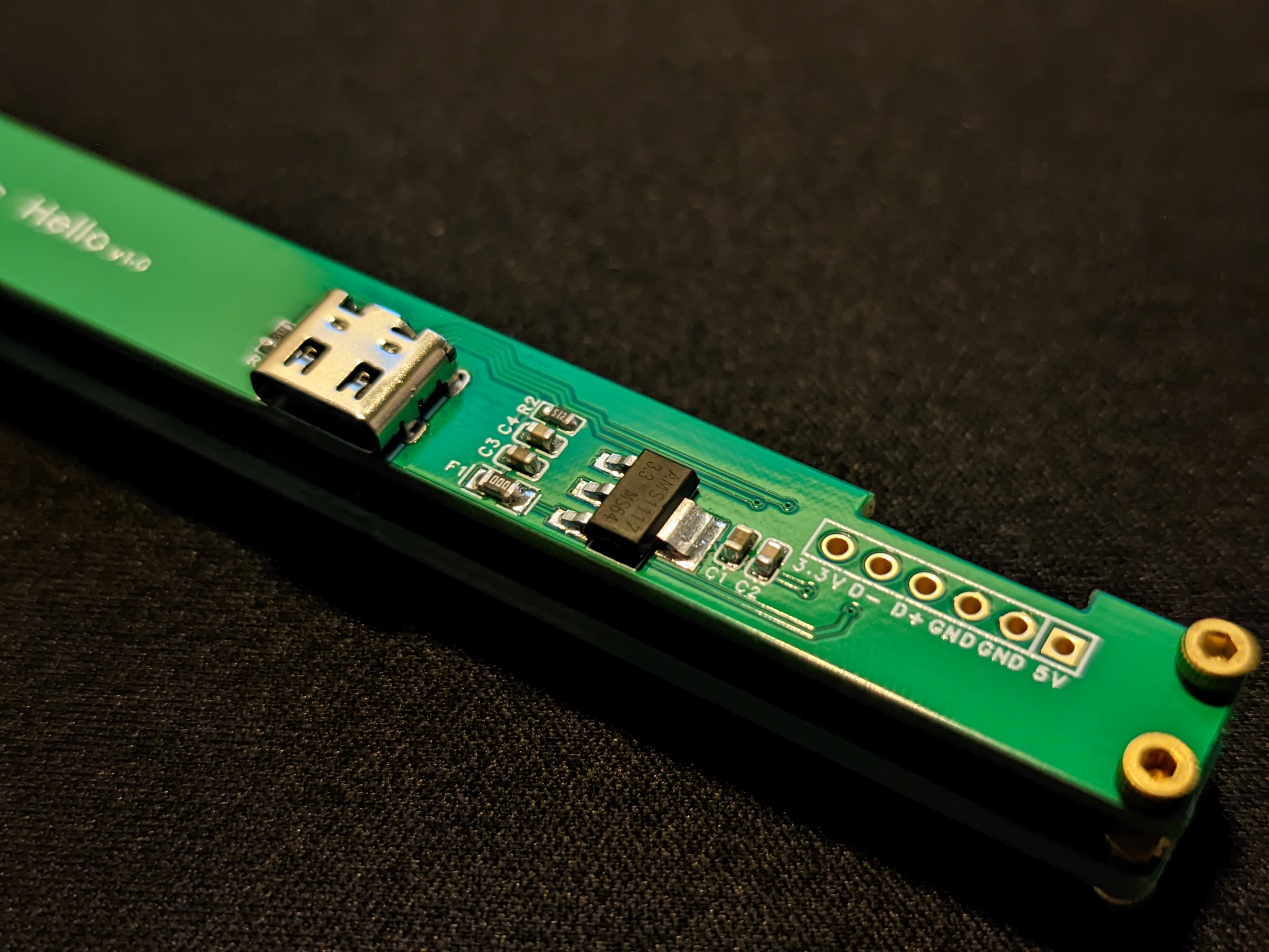
The circuit is quite simple. I used an AMS1117 to step down the voltage to 3.3V.
After soldering all the components on the PCB and measuring them, I started soldering the 0JCXG0 pads. The soldering order for the module's pads is as follows:

Then I used a flying lead method to solder it to the pads on the back (soldering is a bit difficult).
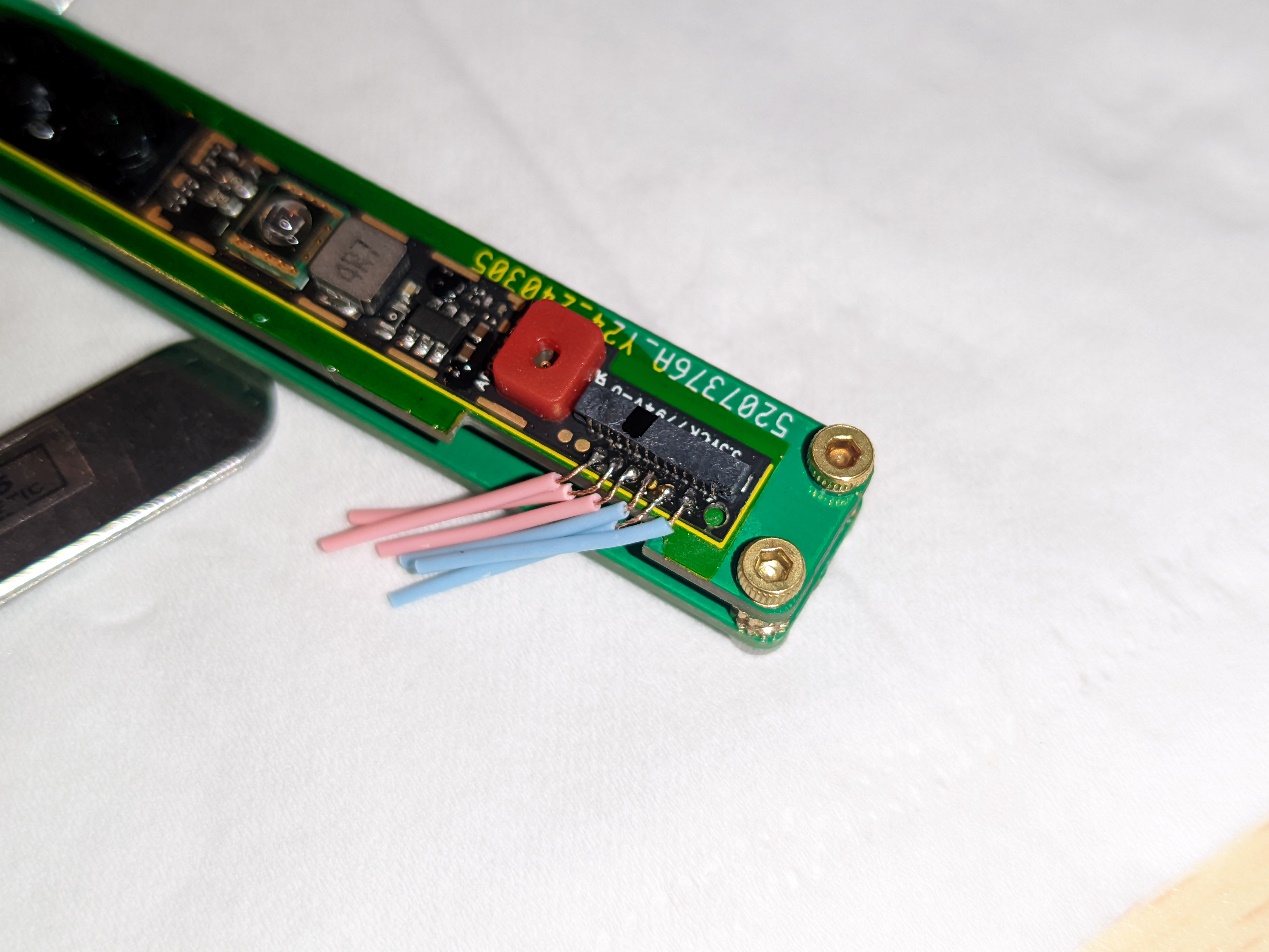
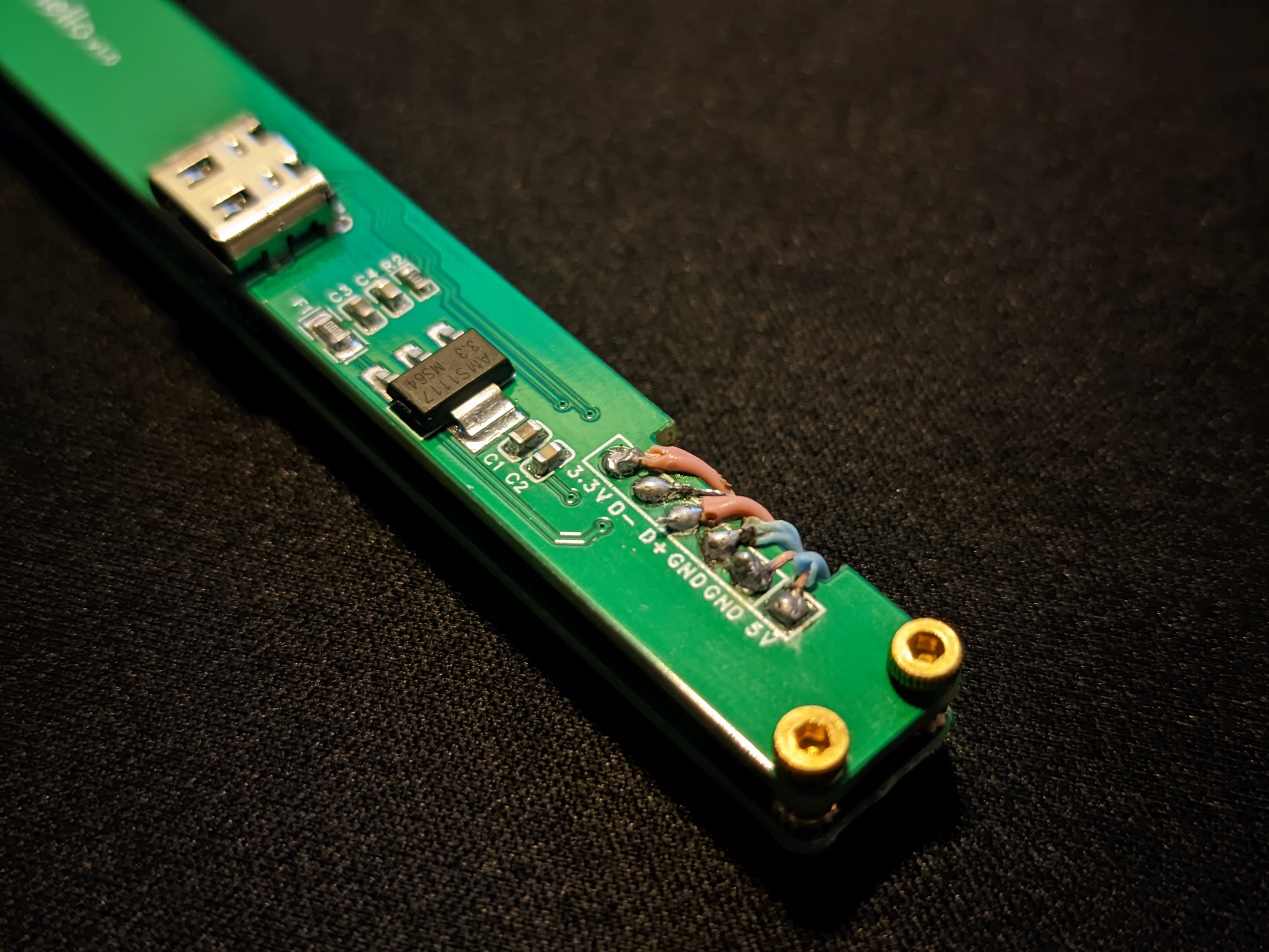
(Please ignore the soldering technique)
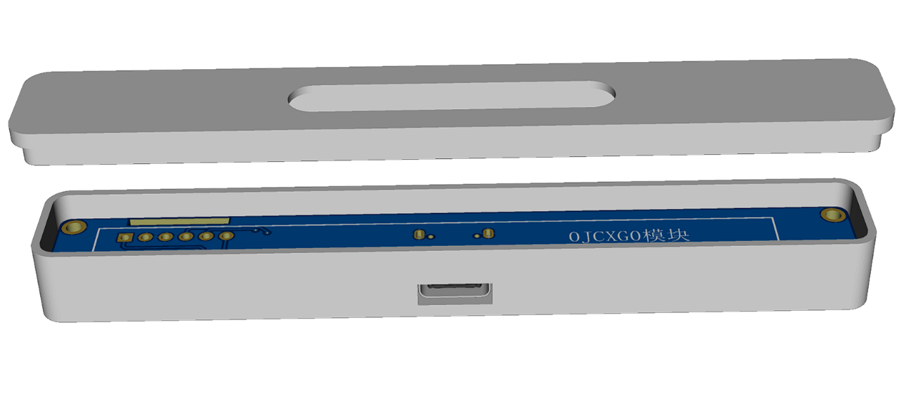
After the module is soldered, begin assembly. Two PCBs are shown here; the PCBs will be used as the outer casing, saving the need for one (not really). The copper pillars are M2*3mm, which is the perfect height. M2*2mm hex nuts are used to attach the PCBs, and M2*3mm hex nuts are used for the driver board.
Overall assembly details
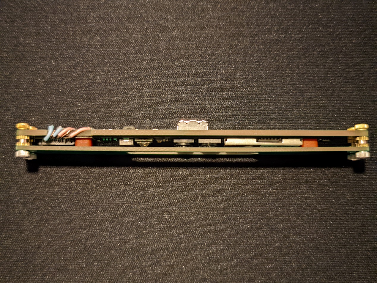
: After assembly, plug in the module and install the driver on the computer.
First, download the driver provided in the attachment, then install

it directly. Click INSTALL
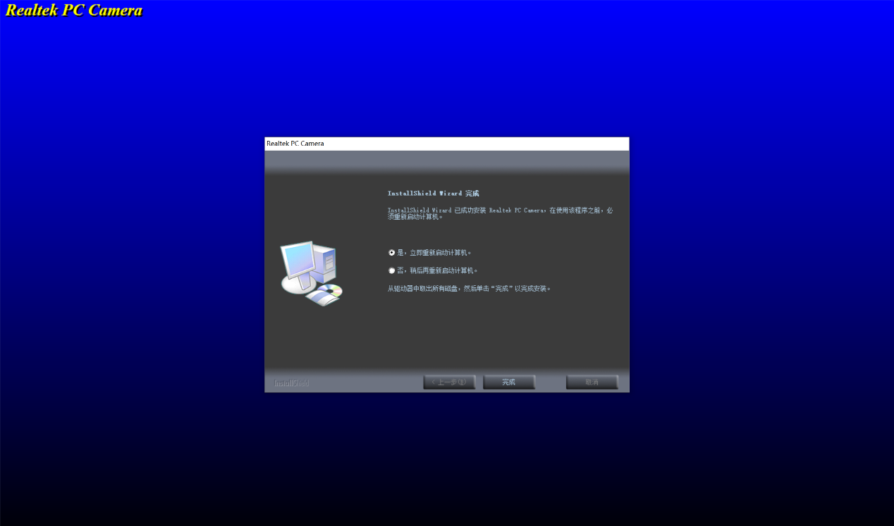
and then Finish. Plug in the module and wait for the system to restart. Then enter your password and open Device Manager. You will find an additional imaging device.

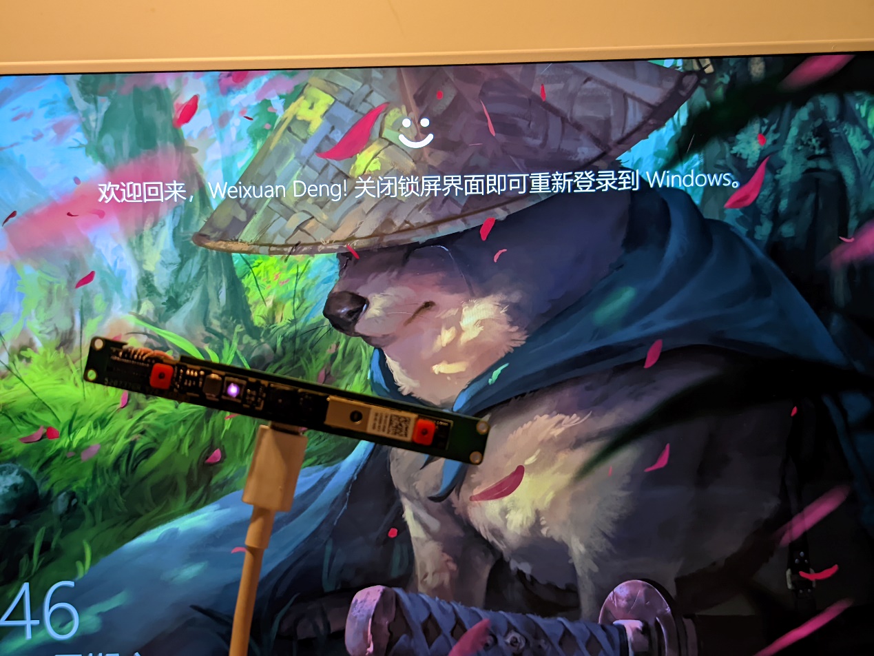
Next, open Settings—Accounts—Sign-in options. Windows Hello is now available.

Finally, after some tinkering, this computer can now happily use Windows Hello.
I also drew a simple outer casing in the attachment...
Friendly reminder: This is supported on Windows 10, but not verified on Windows 11. Also, this device likely does not support hot-swapping; it is recommended to restart the computer after hot-swapping.
3DShell_Driverboard.zip
Realtek-IR-Camera-Driver_TWVGH_WIN_10.0.14393.112.EXE
March 16.mp4
PDF_Windows hello module.zip
Altium_Windows hello module.zip
PADS_Windows hello module.zip
BOM_Windows hello module.xlsx
95704
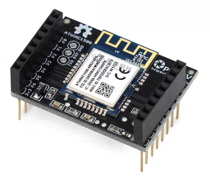
OpenMV WiFi Shield
OPENMV's WiFi extension module is a 1:1 replica, exactly the same as the original.
Preface:
OpenMV WiFi Shield is a great expansion module, but its price of 350 RMB is prohibitive. This replica requires a single unit cost of 30 RMB. The PCB design and appearance are meticulously replicated to closely resemble the official design.
Solution
: The official OpenMV schematic is used to replicate the official
OpenMV schematic
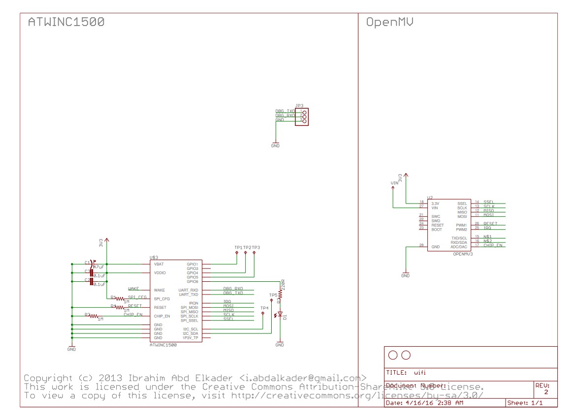
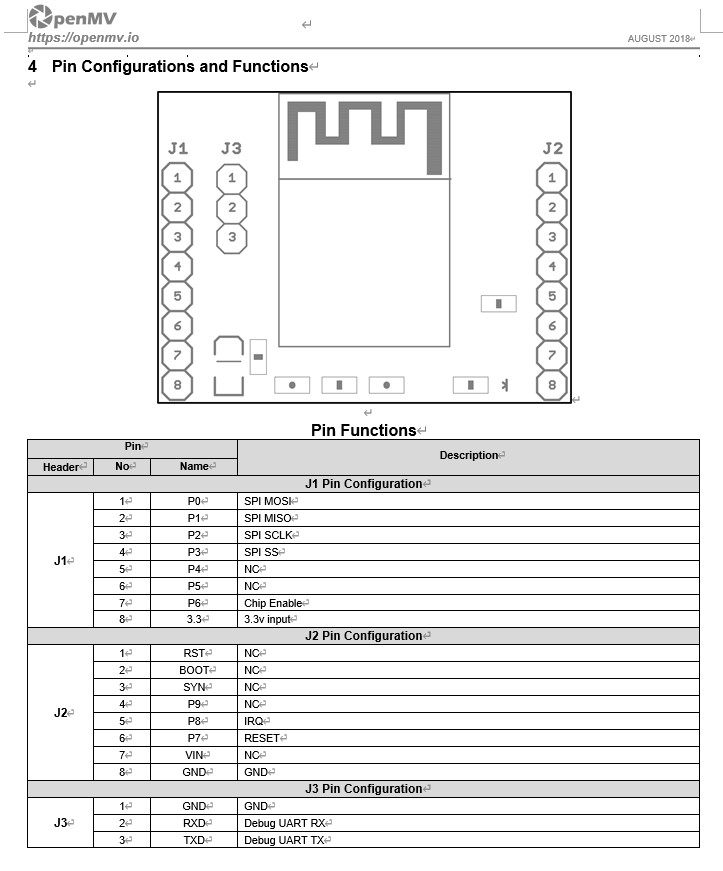
. However, the official schematic is somewhat abstract. The
ATWINC1500
module is expensive if you can't find a cheap alternative. I opted for a Wi-Fi communication board I bought for 25 RMB on Xianyu (a second-hand marketplace). Because of the disassembly, the outer label was washed away with board cleaning fluid.
Effect Diagram:
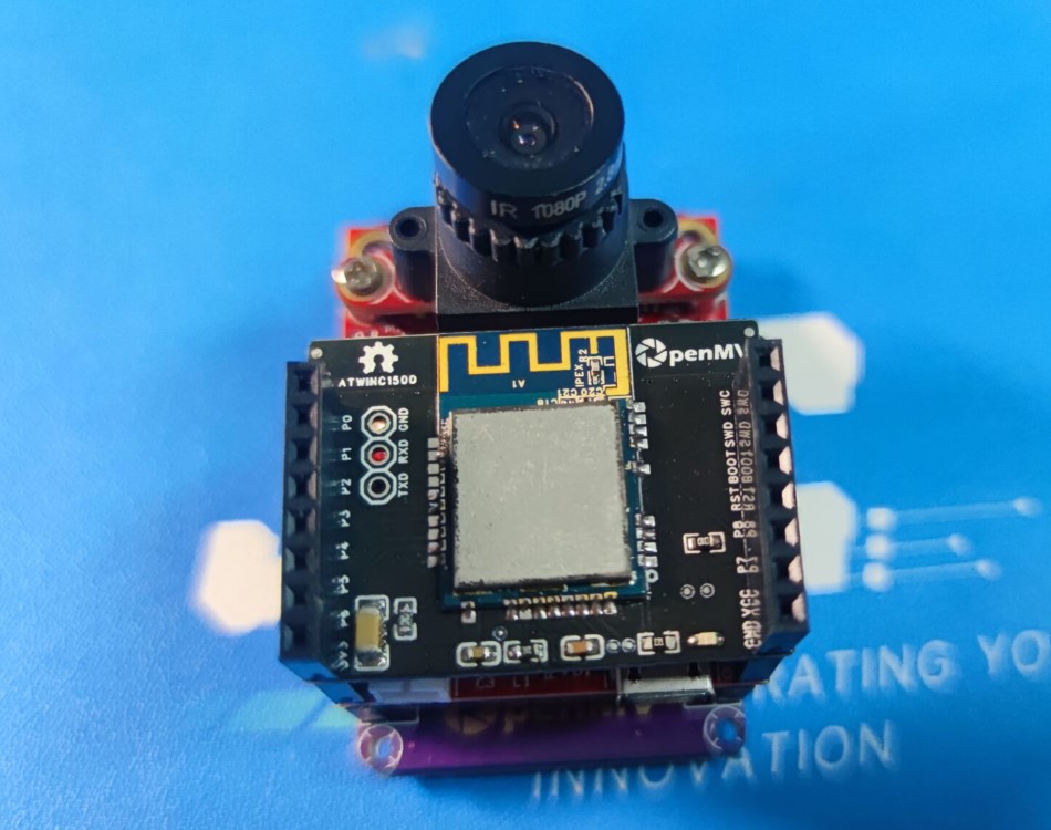
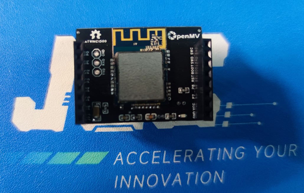
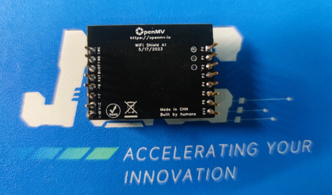
Official Style Diagram
. Firmware
: OpenMV provides firmware.
Copy the firmware to the TF card
: import network
wlan = network.WINC(mode=network.WINC.MODE_FIRMWARE)
wlan.fw_dump("/winc_19_7_6.bin")
PDF_OpenMV WiFi Shield.zip
Altium_OpenMV WiFi Shield.zip
PADS_OpenMV WiFi Shield.zip
BOM_OpenMV WiFi Shield.xlsx
95705
ESP32-S3 Test Verification Board
ESP32-S3 Test Verification Board
The ESP32-S3 test board has been successfully tested and verified without any issues. No I/O pins have been exposed. If needed, it can be directly modified based on some open-source projects.
PDF_ESP32-S3 Test Verification Board.zip
Altium_ESP32-S3 Test Verification Board.zip
PADS_ESP32-S3 Test Verification Board.zip
BOM_ESP32-S3 Test Verification Board.xlsx
95706
TPA3116 Bluetooth Digital Amplifier Board
TDA3116 Bluetooth Digital Amplifier Board
stdin:

Bluetooth uses a KCX-BT010 module.
amp:
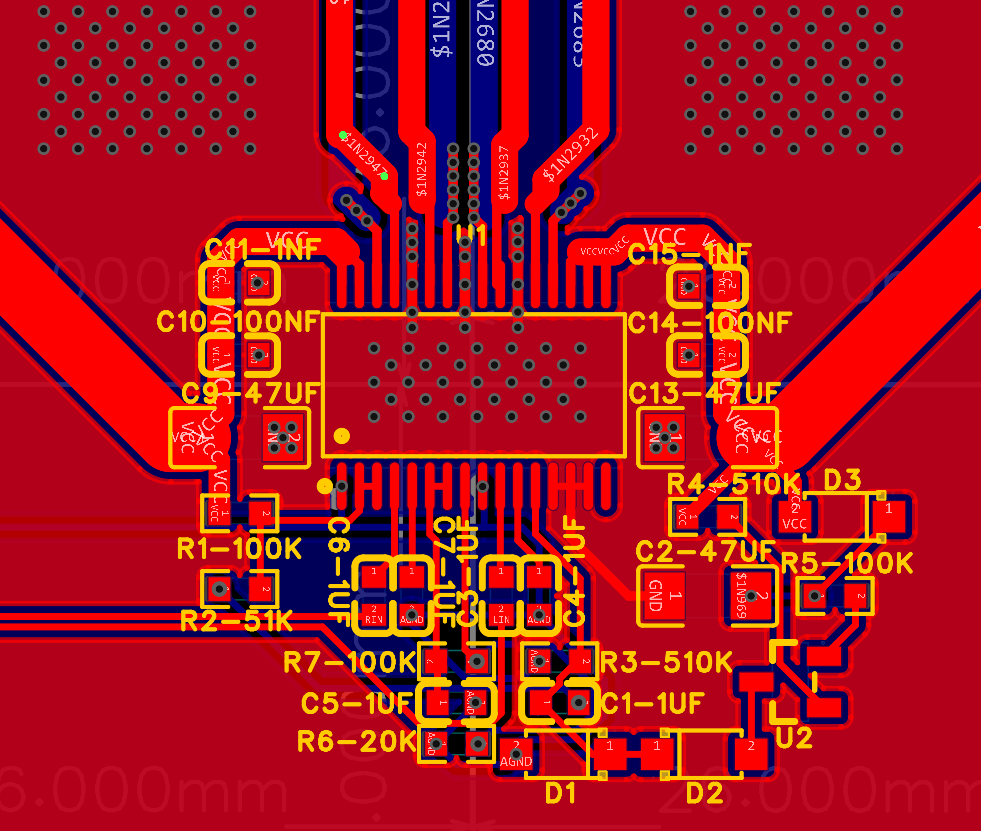
Power amplifier TPA3116D2. Look at my terrible wiring (it shouldn't be a big problem).
audio:

Op-amp uses a 5532P op-amp, 9V power supply (using a surface-mount buck module after the previous failed integrated buck circuit).
Two 220uf solid capacitors are used as output capacitors .
IO:
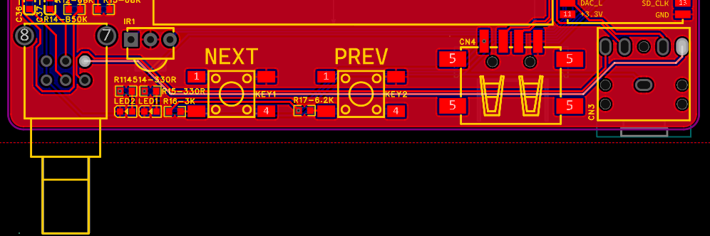
A potentiometer for volume adjustment, then Bluetooth and power indicator lights (using a 5V power supply in series with a 330R resistor), infrared receiver (added on the Bluetooth module out of a momentary lapse of judgment), then previous track and next track (if a USB flash drive is plugged in), aux input.
stdout:

LC filter, around 25kHz, 3116 is available, nothing much to say.
power:

XT60 connector, those who know, know why, maximum current 30A, definitely enough for this little power amplifier.

Also, call me the layout master (not really).
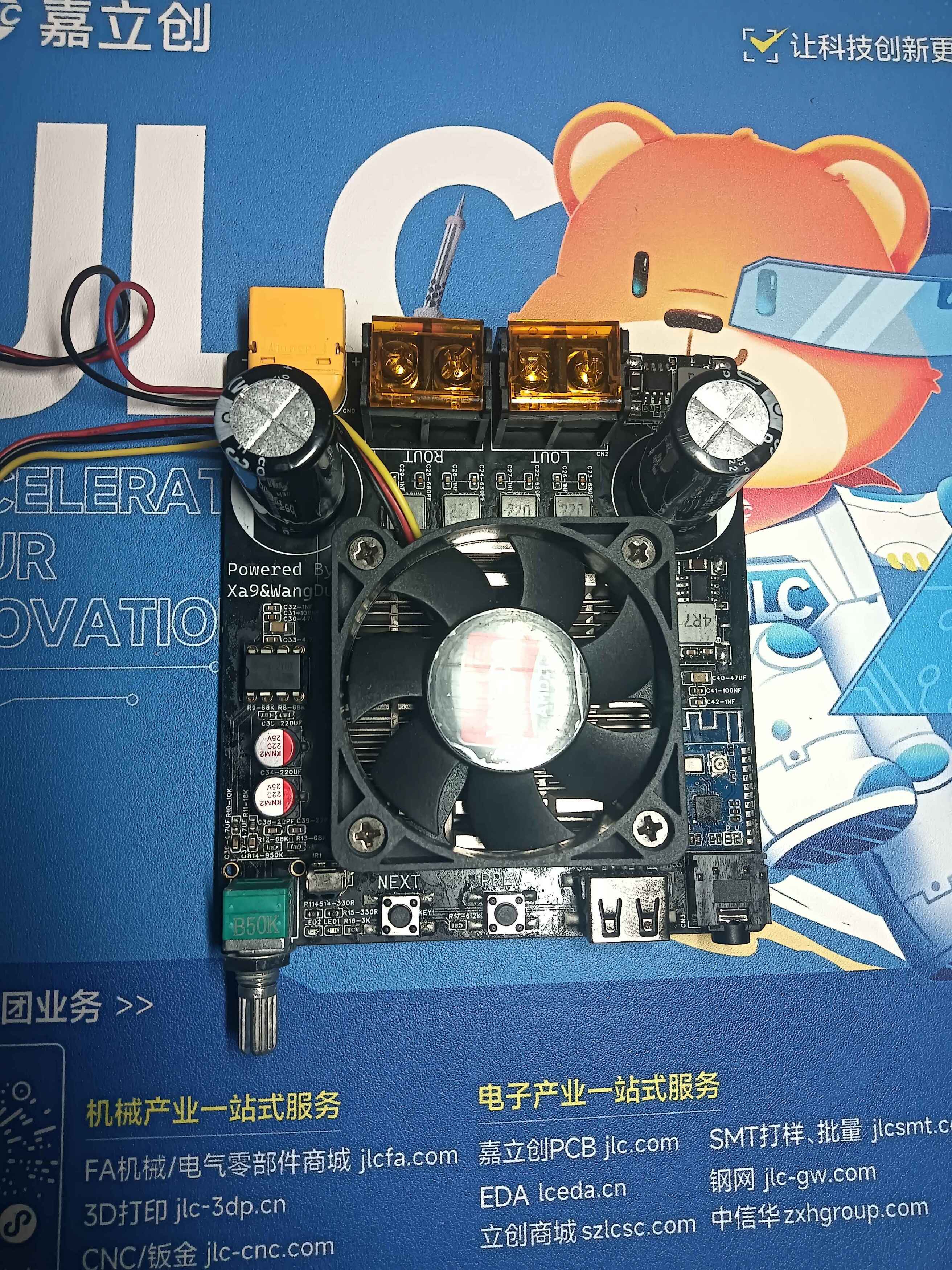
After testing, the amplifier board works normally!
PDF_TPA3116 Bluetooth Digital Amplifier Board.zip
Altium_TPA3116 Bluetooth Digital Amplifier Board.zip
PADS_TPA3116 Bluetooth Digital Amplifier Board.zip
BOM_TPA3116 Bluetooth Digital Amplifier Board.xlsx
95707
True mini lithium battery charge and discharge protection module
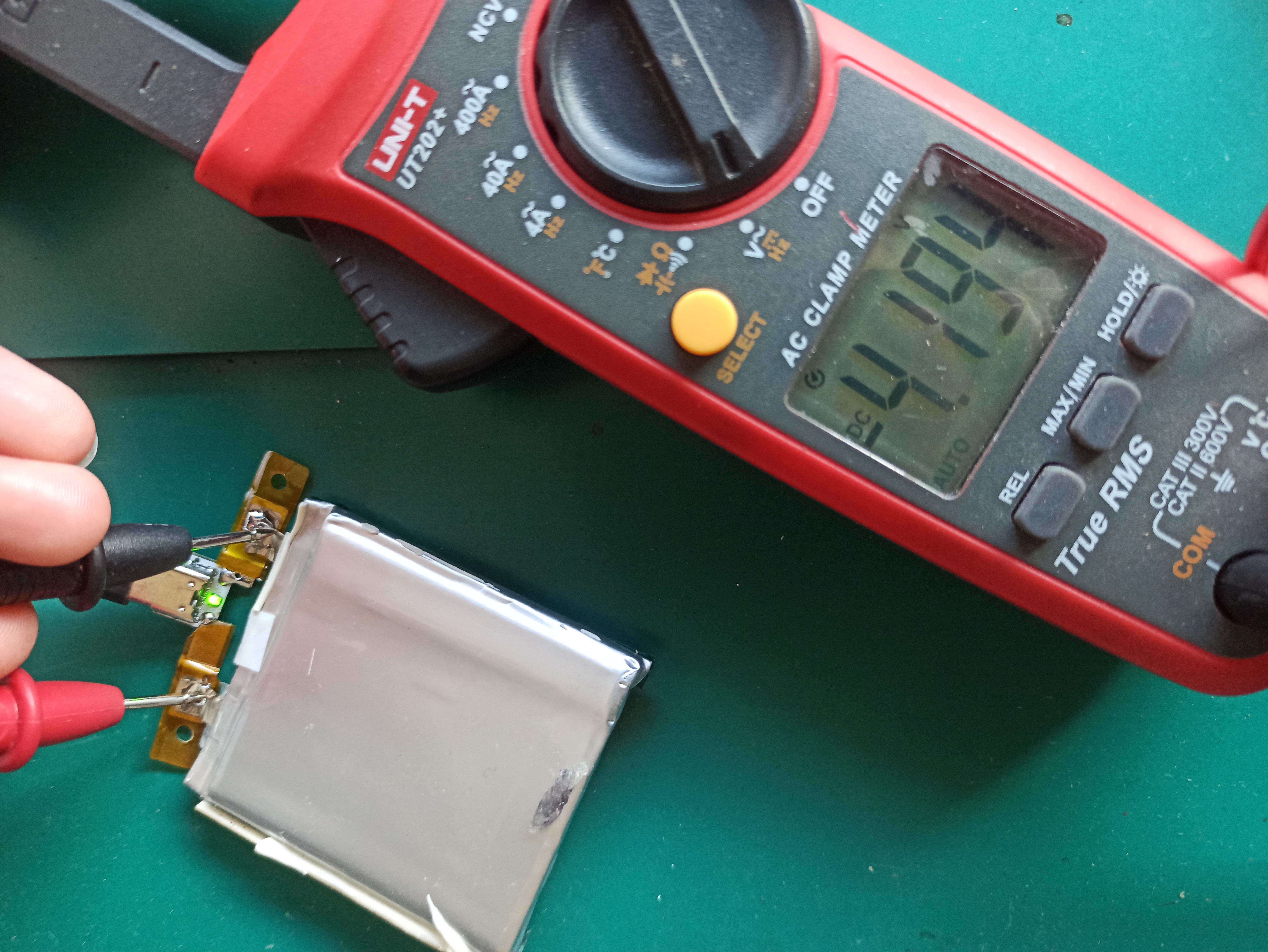
The module uses GX4057 and IP3012A chips. GX4057 is a linear charging protection chip, and IP3012A is a chip integrating charge and discharge protection, providing over-charge protection at 4.2V and over-discharge protection at 2.9V. It is suitable for 18650 batteries and polymer lithium batteries. Verified.
It has been verified that
the two pads on the back of the current Type-C female connector are for discharging, but they can also be used for charging. The two small pads on the bottom connect to the battery.
A red light indicates charging;
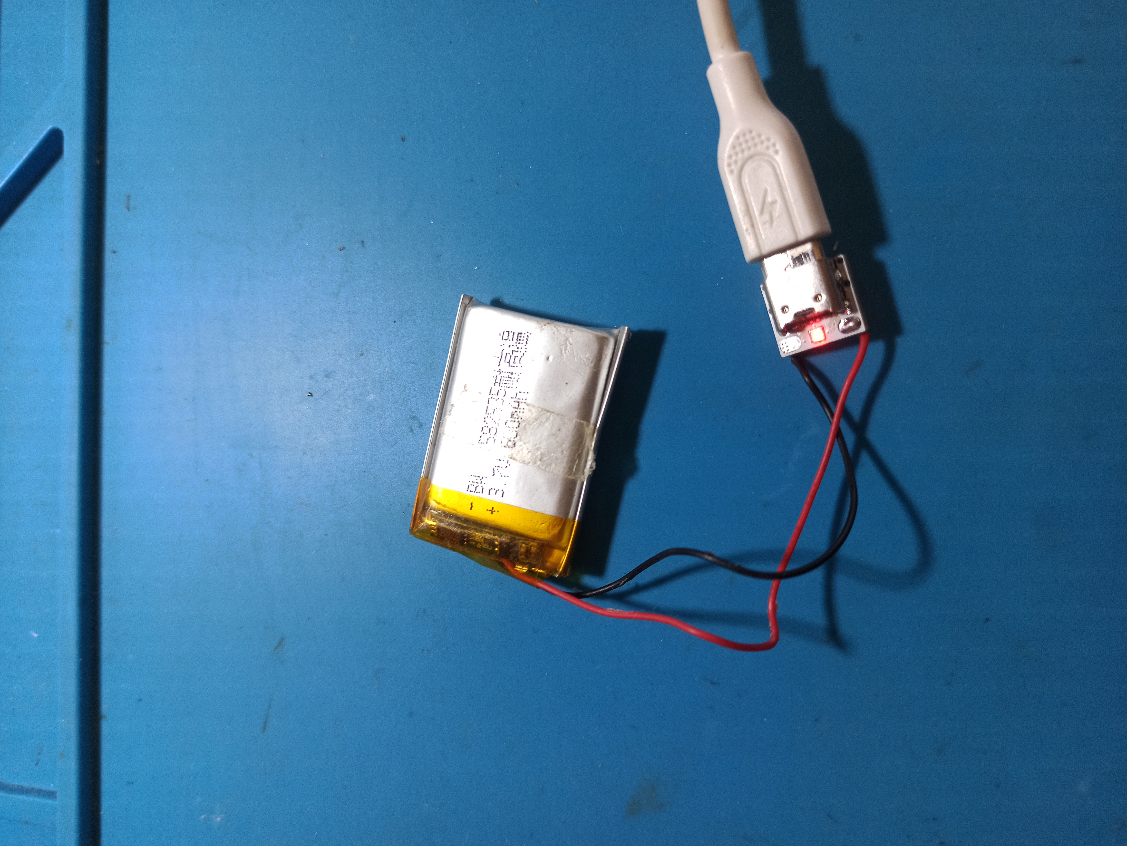
the following image is a test image of the first version.

A green light indicates a full charge;
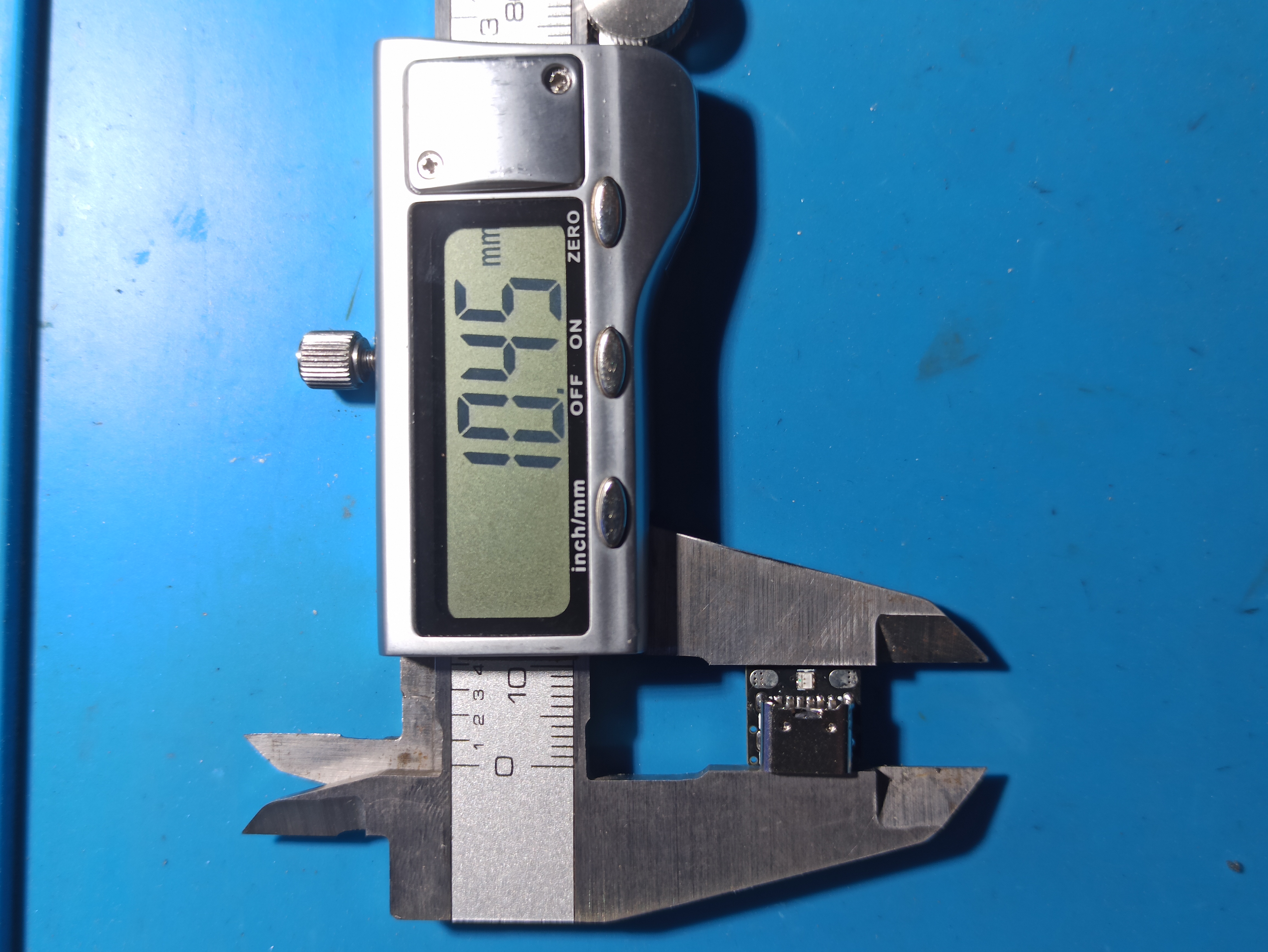
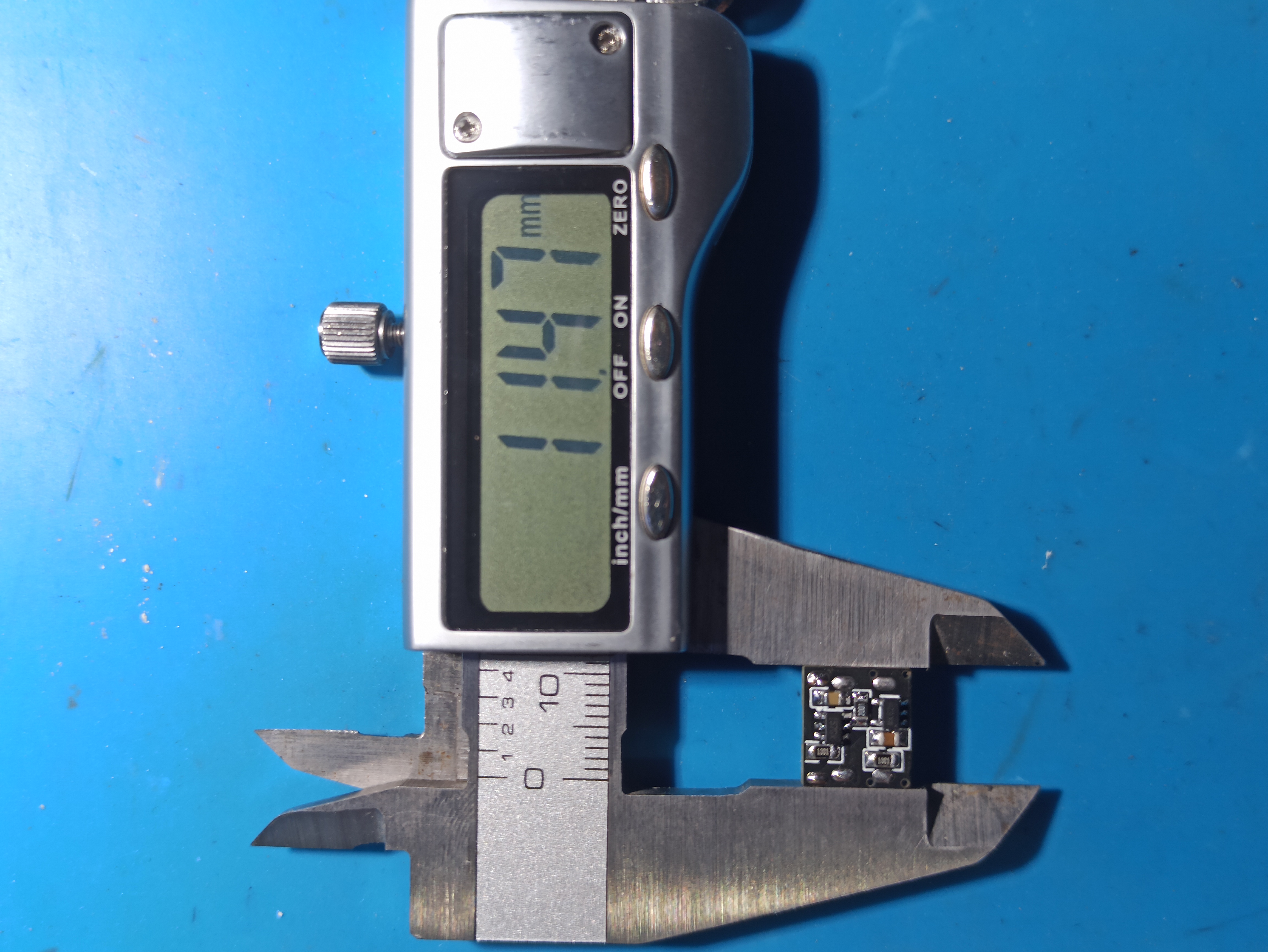
the following image shows the actual dimensions.
Feedback
and improvements are welcome.
PDF_True Mini Lithium Battery Charge and Discharge Protection Module.zip
Altium_TrueMini Lithium Battery Charge/Discharge Protection Module.zip
PADS_True Mini Lithium Battery Charge/Discharge Protection Module.zip
BOM_True Mini Lithium Battery Charge and Discharge Protection Module.xlsx
95708
Gowin FPGA GW1NR-9 Development Board
This learning board uses the Gowin GW1NR-LV9QN88P FPGA chip development board. The circuit diagram and PCB layout are shown in the attachment.
- **Note: The circuit diagram and PCB were drawn using Altium, and there was an error when importing them into LCSC EDA. Therefore, the project files here are for reference only! The original Altium files are provided in the attachment!**
- FPGA Chip Introduction
- Gowin Semiconductor's GW1NR series FPGA products are the first generation of Gowin Semiconductor's LittleBee® family of products. It is a system-in-package (SoC) chip that integrates a large capacity of memory chips based on the GW1N, while also featuring low power consumption, instant startup, low cost, non-volatility, high security, a variety of package types, and ease of use. [Chip Datasheet](https://cdn.gowinsemi.com.cn/DS117-3.0_GW1NR series FPGA product datasheet.pdf)
- The chip model used in this project is **GW1NR-LV9QN88P**, with 608Kbits of flash memory and 64Mbits of PSRAM. It features an onboard 50MHz crystal oscillator, QSPI flash, RGB LEDs, 2 buttons, an Arduino interface, and 2 PMOD interfaces. **Examples are provided in the attachment.**
- Power Supply Section
- The power supply chip used is **EA3036C**, a 3-channel DC-DC output providing 1.2V core voltage, 3.3V auxiliary voltage, and IO Bank voltage for the FPGA, and 1.8V PSRAM voltage. IO Bank3 and PSRAM are powered together. If PSRAM is not used, 3.3V can be provided to IO Bank3. [Chip Datasheet](https://item.szlcsc.com/596623.html)
- The power supply voltage is 5V, which can be input from the DC interface or JTAG interface.
- Download and Debug
- JTAG+UART debugger using [Sipeed RV debugger plus](https://item.taobao.com/item.htm?_u=hrhang672db&id=648095486021&spm=a1z09.2.0.0.235c2e8dzzLPRL&skuId=4669873852198), provides JTAG and UART, but the firmware needs to be flashed by yourself. **Firmware is provided in the attachment**. Alternatively, you can use other debuggers if you don't want the hassle. The downloaders I've used include [Xiaoyanjing Semiconductor](https://item.taobao.com/item.htm?_u=t2dmg8j26111&id=619026488991&spm=a1z0k.7386009.0.0.6cfe37deVMHIjQ&skuId=4634169105530) and [Xiaomeige FPGA](https://item.taobao.com/item.htm?_u=hrhang6c531&id=738178487048&spm=a1z09.2.0.0.7d282e8dRDVG4A).
The JTAG is located in IO Bank 3 and is equipped with a 74LVC1T45 level converter chip.
Schematic PCB.zip
Debugger Firmware.zip
FPGA Examples.zip
PDF_Gaoyun FPGA GW1NR-9 Development Board.zip
Altium_Gaoyun FPGA GW1NR-9 Development Board.zip
PADS_Gaoyun FPGA GW1NR-9 Development Board.zip
95714
Weird little lamp
A desktop ornament resembling a hand grenade
A desktop ornament designed to resemble a hand grenade:
Shell Shape: Mimicking the classic shape of a hand grenade, it features a round base and a raised handle at the top, resulting in a compact and three-dimensional design.
Material and Color: The shell is printed with white environmentally friendly PLA material, offering a smooth surface, excellent texture, and a simple yet elegant look.
Size: The shell is of moderate size, making it easy to place on a desktop or bookshelf as a decorative piece.
Features:
RGB LEDs: Built-in multi-color RGB LEDs provide rich and varied lighting effects, supporting multiple colors and flashing modes to enhance visual appeal.
Lighting Control: Users can adjust the light color and brightness as needed.
USB Power Supply: USB powered, allowing for easy connection to a computer, power bank, or USB adapter.
Application Scenarios:
Home Decor: Can be used as a desktop ornament or bookshelf decoration to create a warm and inviting atmosphere.
Office: Placed on an office desk or in a meeting room, it adds fun and vibrancy to the work environment.
Business Gift: A creative gift for friends, colleagues, or business partners, showcasing personality and taste.
Precautions:
Safe Use: Do not confuse this with an actual hand grenade. Use it as a decoration only. Do not throw or disassemble.
Avoid Prolonged Continuous Use: To extend the life of the LEDs, avoid prolonged continuous use and allow for appropriate breaks to prevent overheating.
This desktop ornament not only boasts a unique design but also incorporates lighting effects, adding fun and vibrancy to your living space. It is a creative product worthy of collection and display.
WeChat image_20240229153313.jpg
WeChat image_20240229153201.jpg
Electronic Entertainment.mp4
PDF_Weird Little Lamp.zip
Altium_Weird Little Lamp.zip
PADS_Weird Little Lamp.zip
BOM_Weird Little Lamp.xlsx
95716
electronic


 京公网安备 11010802033920号

 SM5420-060-A-H-T


