Signal Input:
Two analog signal input channels.
Input signal range: -15V to +15V.
A 1MΩ input impedance is achieved through a series resistor voltage divider. The relay switch circuit selects direct connection/reduction by 20 times.
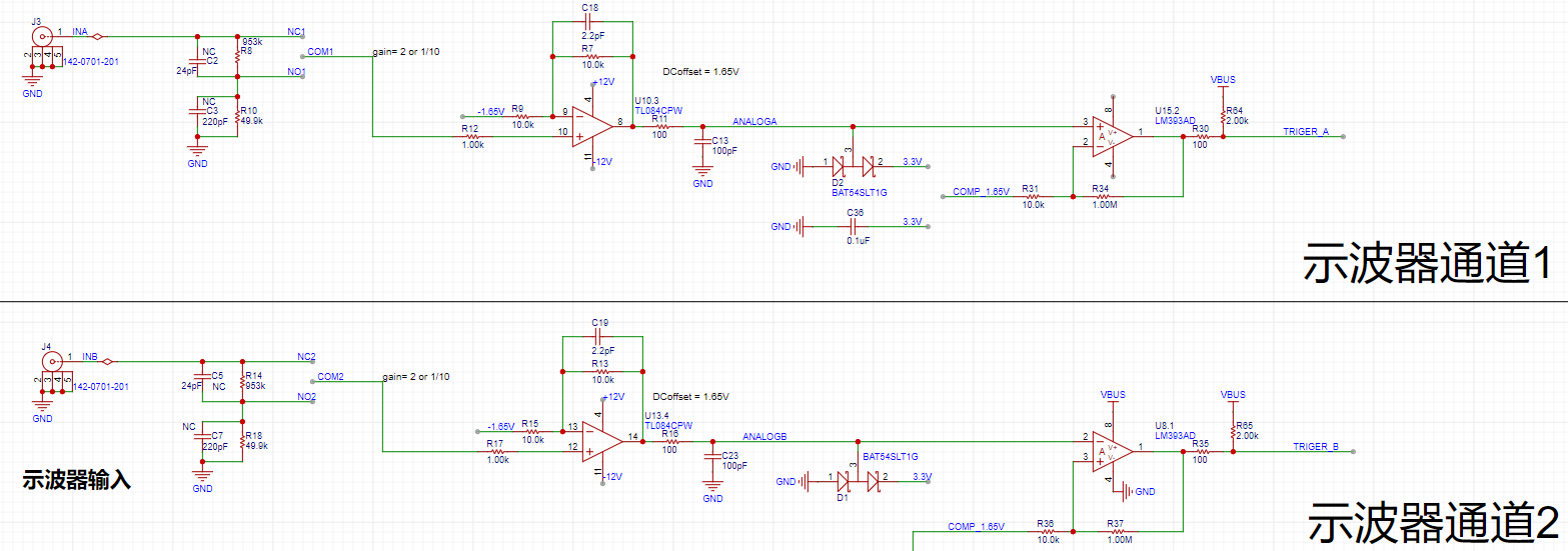
Because the STM32H750's internal VREF uses a 3.3V power supply, the ADC acquisition range is 0~3.3V, and the analog input voltage range is -15V~15V. Therefore, the signal needs to be reduced by at least 30/3.3 (approximately 9 times). Adding a positive offset of 3.3/2 = 1.65V, complete signal acquisition is achieved. Here, the signal is reduced by ten times (resistor parameters are easy to choose).
When the input signal is small, a relay is used to select the direct connection circuit to ensure that the signal entering the ADC is as large as possible. Combined with a 16-bit ADC, the sampling results are accurate and reliable.
The pre-amplifier is a non-inverting amplifier, which can amplify the signal by 2 times and offset it positively by 1.65V
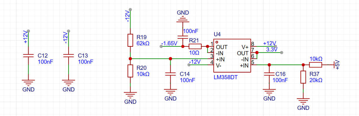
(the -1.65V above is obtained by voltage division of -12V through resistors and voltage follower).
The post-amplifier is a hysteresis comparator. The non-inverting input is a DC trigger signal generated by DAC1_OUT1 to achieve a square wave output, which is convenient for subsequent triggering of ADC signal acquisition, frequency measurement, etc. A suitable trigger signal can also make the waveform display stable.
The series Schottky diode potential clamping prevents damage to the
power supply section of the core board:
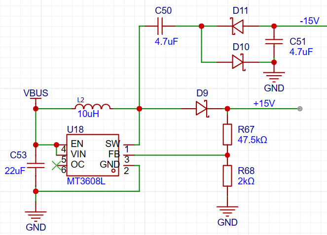
DC-DC boost and negative voltage generation circuit. I forgot the principle, but it is roughly that the chip can maintain the voltage between FB and GND at 0.6V, and the resistor ratio can output 15V. The voltage at SW oscillates between 0 and 15V. When SW outputs 15V, D10 conducts and C50 charges, resulting in a 15V voltage difference at C50 when fully charged. When SW outputs 0V, D11 conducts and C50 discharges, transferring the 15V voltage difference to C51, thus enabling the output of -15V.
(For the wiring of this part of the circuit, it is recommended to refer to the manual for precautions. Improper wiring can easily lead to boost failure.)
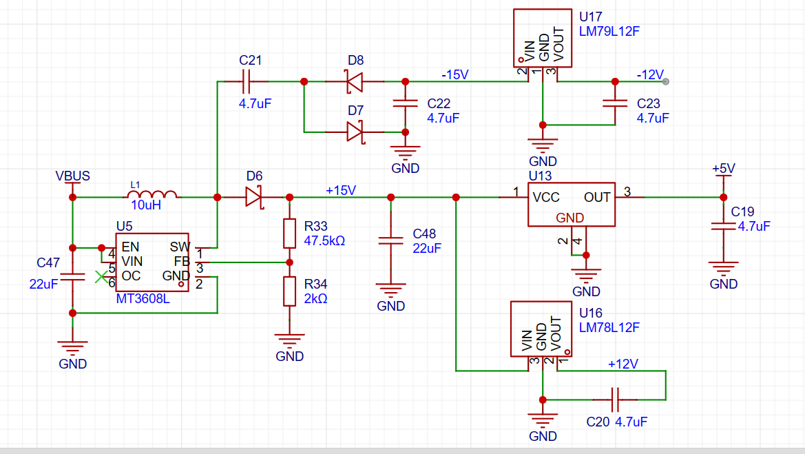
After obtaining ±15V, ±12V and +5V can be directly obtained through LDO (the 5V from the external power supply is not used directly here because a negative offset is needed to provide the analog output channel later. The external power supply fluctuates greatly, while the 5V obtained through LDO is very stable).
Analog output section:
a second-order RC filter to implement the low-pass filter function.
The STM32 ADC output range is 0~3.3V. In order to achieve the output requirement of -10V~+10V, the signal needs to be amplified by 20/3.3 (about 6 times) and then offset downward by 10V.

The 2V in the diagram is obtained from 5V through resistor voltage division and then through voltage follower.
Since Vn=Vp, Vout=(Vp-2)*5 + Vp = 6Vp -10V. The -10V offset is obtained in this way.

The ADC has a 12-bit output precision. When the DAC code value is reduced to output a small signal, to achieve a voltage resolution of 7 bits (i.e., a vertical resolution of 128 points), the waveform must be attenuated by 128/4096 = 1/32. This translates to an output voltage range of ±10V/32 = ±0.3215V. For signals smaller than ±0.3125V, further reducing the code value would result in insufficient DAC resolution, leading to noticeable waveform steps. Therefore, when outputting signals smaller than ±0.3125V, the output is switched from direct output to a resistor divider to attenuate the waveform by 1/20, ensuring sufficient voltage resolution for small signals.
The impedance to ground for both output speeds is 50Ω.
Button descriptions: KEY1: Backward selection KEY2: Forward selection KEY3: Channel 1/2 trigger selection KEY4: ADC on/off
Software section:
1. Timers used:
LPTIM1: 1. Triggers DMA every 20ms to refresh the screen 2. Detects button status every 100ms
LPTIM2: Timeout function. If a trigger signal is generated within 100ms, the frequency will be calculated in the TIM2 interrupt + ADC acquisition will be enabled + the timeout function will be disabled. If a timeout occurs, ADC acquisition will be enabled and the timeout function will be disabled.
TIM2: CH1, CH2 capture the trigger signal generated by the comparator
TIM3: Encoder mode count
TIM6: Triggers DAC1_OUT2 to adjust the frequency and peak-to-peak value
2. ADC:
16-bit ADC1 + ADC2 dual-channel acquisition to improve the sampling rate
3. DMA:
DMA of 3 peripherals is enabled: ADC acquisition (highest priority), DAC sends analog signals, SPI sends data to the screen (lowest priority)
4. X/Y axis switching:
X-axis switching: Adjusts the sampling range by changing the ADC sampling rate. A higher sampling rate results in a longer sampling time and a wider displayed signal. Six sampling times are available: 8µs, 16µs, 32µs, 64µs, 160µs, 320µs, and 640µs.
Vertical axis switching: Obtained by processing the ADC data. Six levels are available: 100, 200, 500, 1000, 2000, and 5000 mV/division.
5. Fast Fourier Transform (FFT ):
I don't understand
why the blue signal at the bottom of the screen is the FFT signal.
Here is the official tutorial: Chapter 1 Function Division and Preparation (yuque.com).
The official sample code will be attached at the end of the article
. Finally: I made some modifications to the code based on my own situation and preferences, including: 1. Because I used EC11, switching would jump two levels, which I changed back in the program. 2. Pressing EC11 resets the system. 3. Modifications to the waveform and the selected highlight color.
Video Demonstration: Hardwood Classroom STM32H750 Oscilloscope & Signal Source Expansion Board_Bilibili_bilibili


 京公网安备 11010802033920号

 2SC1945


