The mini FOC driver contains the basic modules for FOC operation, including current collection, bus voltage detection, inverter bridge and drive, and power supply parts. The mini FOC driver can be easily used in a variety of situations due to its small size. The driver board and control board adopt a stacked board design and can be replaced with any platform driver, such as ARM, DSP, ESP, etc. Supporting STM32F405RGT6 control board open source link:
miniFOC control board STMF405RGT6 - Lichuang EDA open source hardware platform (oshwhub.com)
For the STM32 control board, you can use ST MCworkbench for software development . The graphical configuration interface can quickly help you establish the FOC driver. You can also use STM32CubeMX to build the FOC system yourself. For details, please refer to:
1. [STM32-HAL library] Build FOC vector control step by step (with C code)
2. C language code implementation of FOC and SVPWM
3. PMSM vector control algorithm debugging process
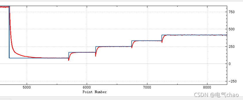
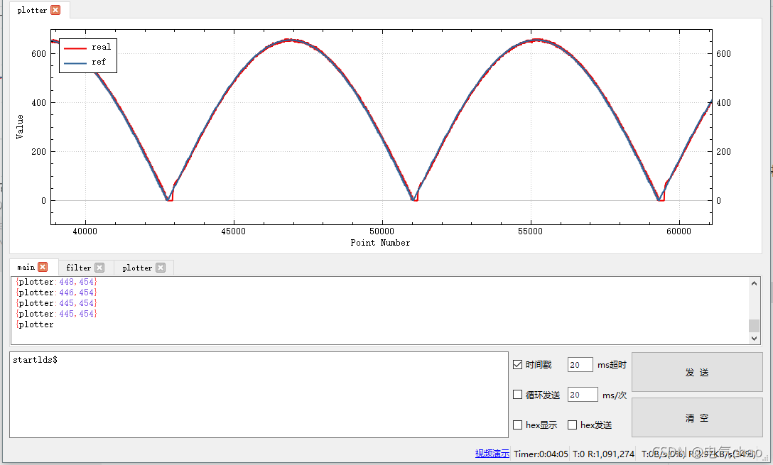
The input voltage of the miniFOC driver is 24V, the current operational amplifier gain is 15, and it is designed for a maximum current of 11A. It has a common interface for photoelectric encoders and Hall sensors. The power supply filter capacitor is a 1210 type package with 100UF capacitor and a 0.1uf 1206 type package with voltage resistance . The value is 50V . The simple miniFOC driver does not yet include many improved functions such as power supply transient suppression, RC absorption network, isolation and protection, and only provides the smallest module system for driving PMSM or BLDC. The figure shows the curve diagram of the speed loop step signal tracking and the sinusoidal signal tracking. The attachment shows a schematic video of the drive wheel hub motor. The UI uses the ugui open source library. For specific usage, please refer to:
Note: The input terminal of IR2136SPWM is active low
The level is limited, corrections are welcome!

All reference designs on this site are sourced from major semiconductor manufacturers or collected online for learning and research. The copyright belongs to the semiconductor manufacturer or the original author. If you believe that the reference design of this site infringes upon your relevant rights and interests, please send us a rights notice. As a neutral platform service provider, we will take measures to delete the relevant content in accordance with relevant laws after receiving the relevant notice from the rights holder. Please send relevant notifications to email: bbs_service@eeworld.com.cn.
It is your responsibility to test the circuit yourself and determine its suitability for you. EEWorld will not be liable for direct, indirect, special, incidental, consequential or punitive damages arising from any cause or anything connected to any reference design used.
Supported by EEWorld Datasheet
EEWorld
subscription
account

EEWorld
service
account

Automotive
development
community

Robot
development
community

About Us Customer Service Contact Information Datasheet Sitemap LatestNews


Room 1530, 15th Floor, Building B,
No.18 Zhongguancun Street,
Haidian District,
Beijing, Postal Code: 100190
China
Telephone: 008610 8235 0740
 京公网安备 11010802033920号

 NRSG151M10V5X11TRF


