Twin Colorful Light Ornament
Project Description:
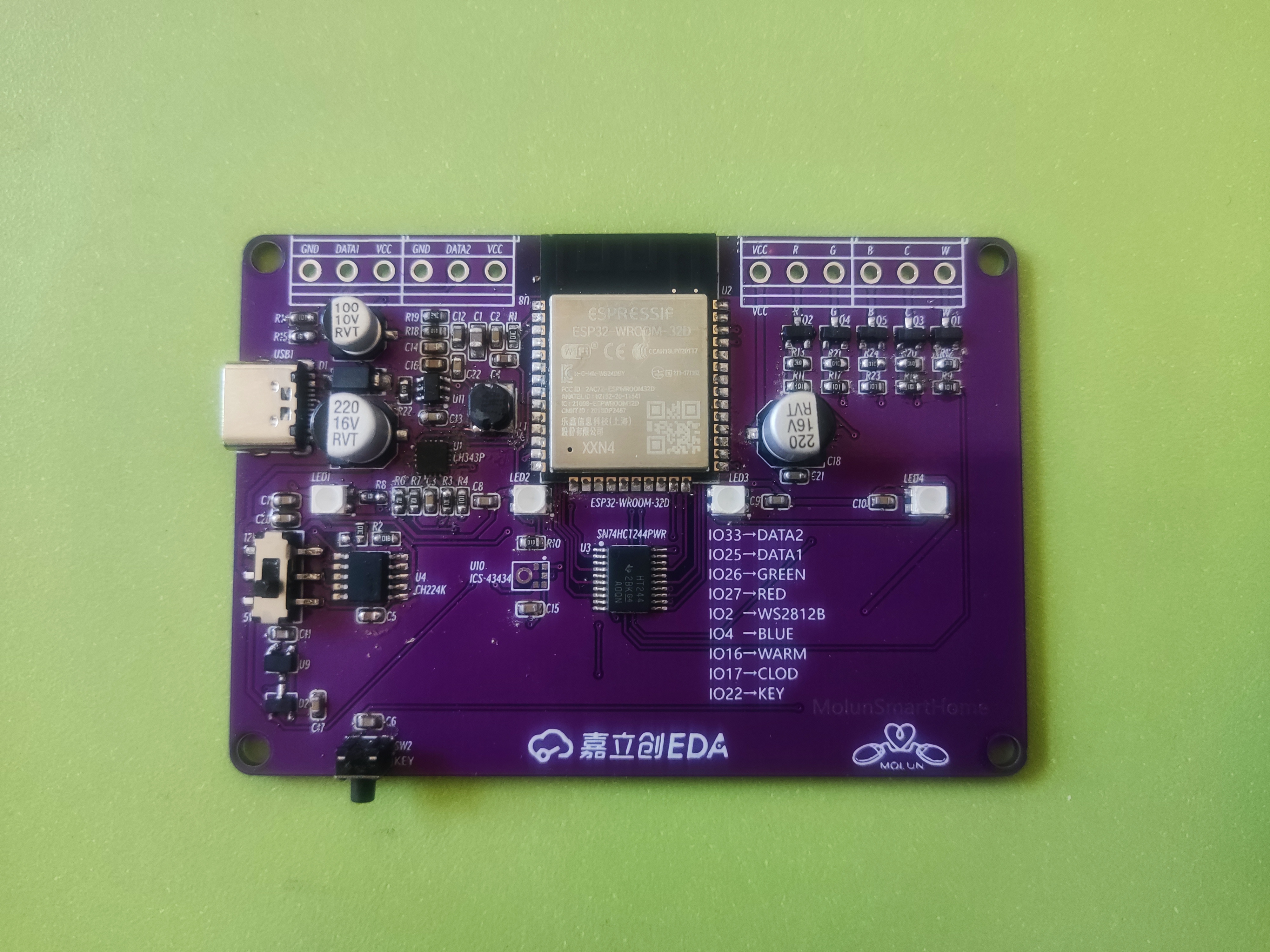
Inspired by the LED driver board design from HACK Labs, this multi-channel colorful light driver board uses the ESP32-WROOM-32D as the main controller. It features four WS2812B LEDs in a 3528 package, a 3D-printed shell, and a 1.5mm acrylic panel in a recessed area on top. The panel is printed with a photo of my twin babies at their one-month celebration, making it a commemorative ornament!
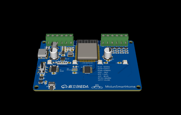
It can connect to two external WS2812B LED strips and drive one RGBCW LED strip!
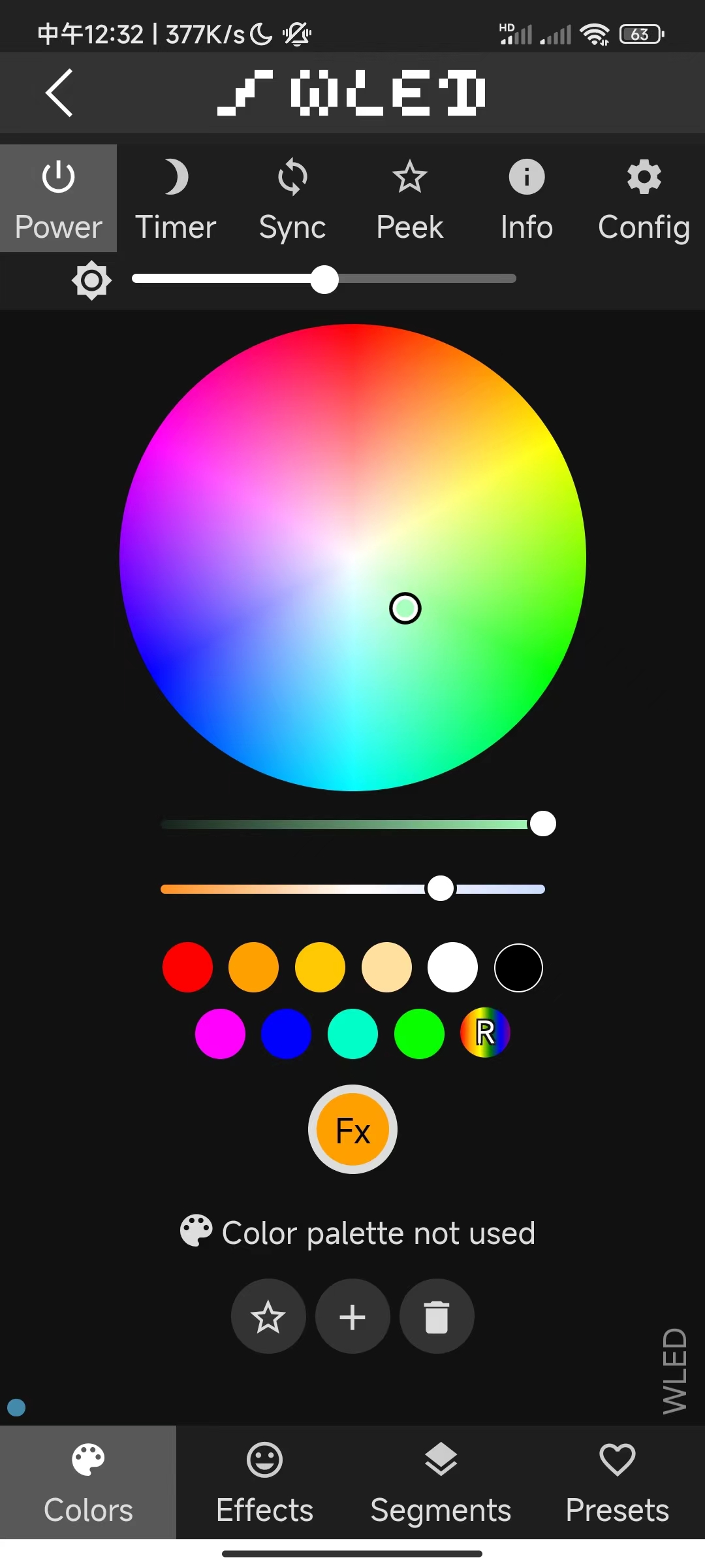
The program uses WLED or a custom-written program connected to Hassio or a lighting platform to achieve remote control functions.
Physical Display:
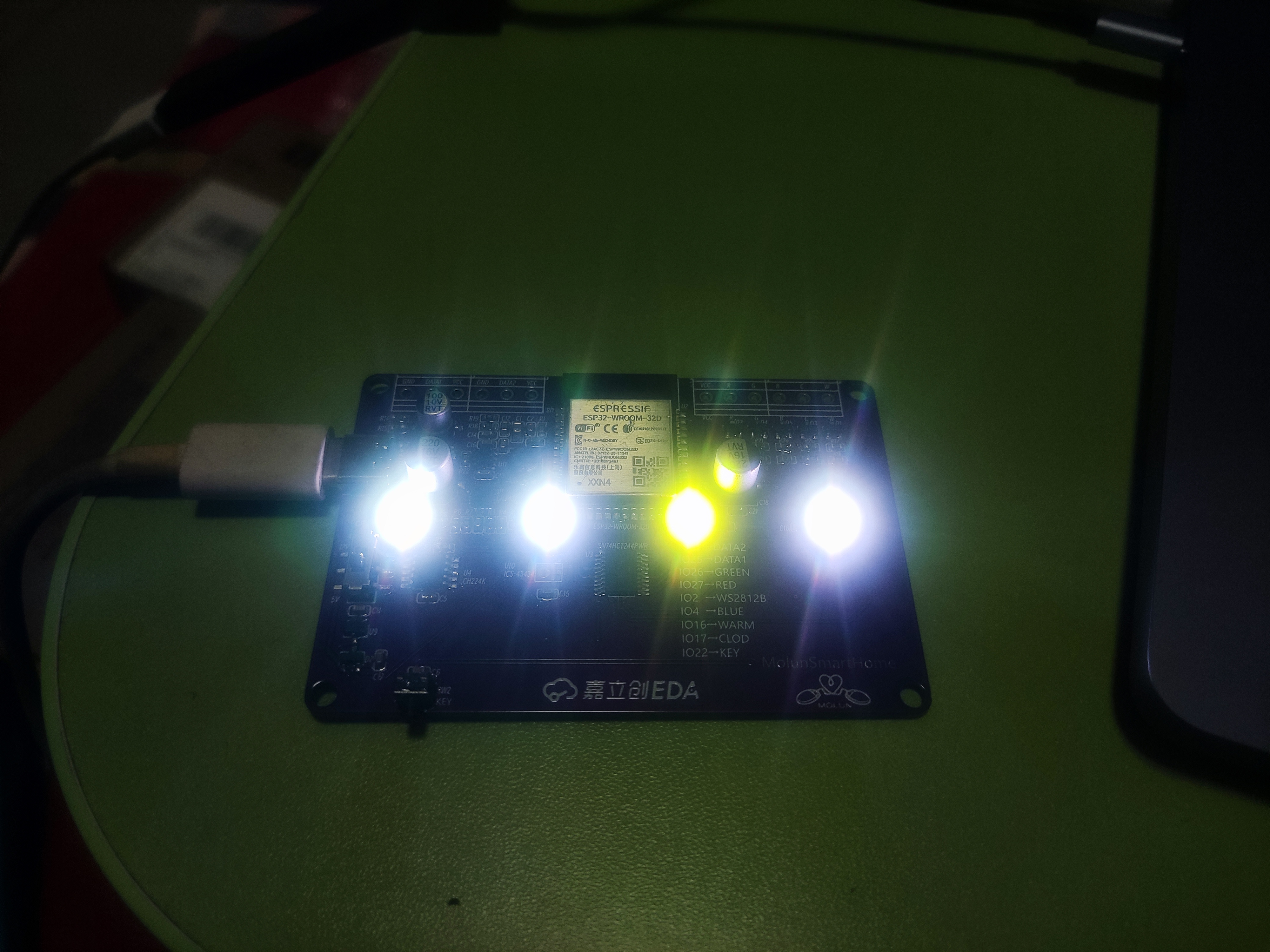
Showing off my twins:

Programming:
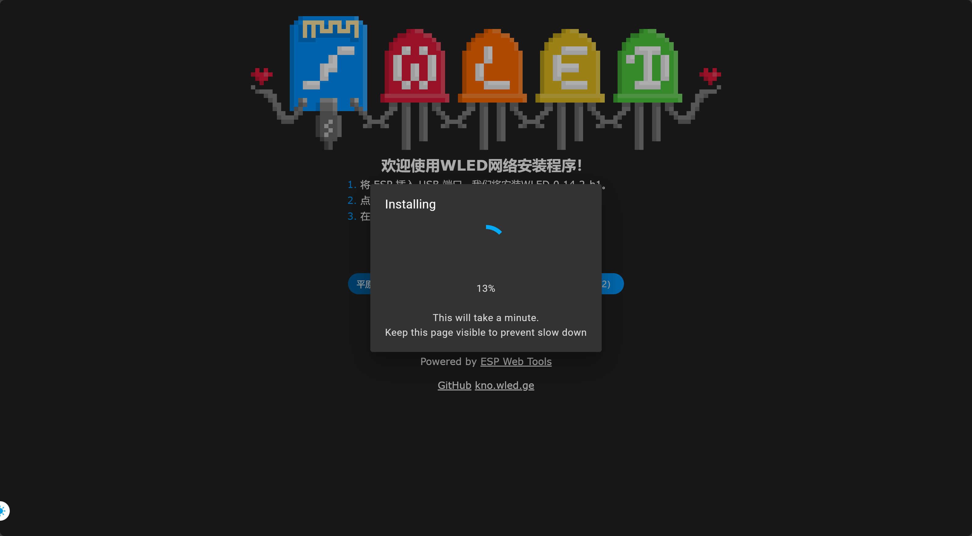
WLED online programming address: https://install.wled.me/
PDF_Call for Entries_Twin Colorful Light Ornaments.zip
Altium_Call for Submissions_Twin Colorful Light Ornaments.zip
PADS_Call for Submissions_Twin Colorful Light Ornaments.zip
BOM_Call for Submissions_Twin Colorful Light Ornaments.xlsx
95822
PCB Colorful Lanterns
PCB colorful lantern, ESP-12F main controller, driving WS2812B LED beads.

The PCB lantern uses WS2812B LEDs and is driven by a NodeMCU or a self-soldered ESP-12F. The firmware can be WLED.
VID_20240303_221700.mp4
PDF_PCB Colorful Lanterns.zip
Altium_PCB Colorful Lanterns.zip
PADS_PCB Colorful Lanterns.zip
95823
Lichuang Liangshan School - Intelligent Car
LCSC Liangshan School - Intelligent Car, 10*10 board available for free board making.
The smart car
was based on LCSC's teaching materials, from circuit design to PCB layout. Due to insufficient funds, the board was modified to be 10*10, and the battery was placed directly inside without a battery holder.
Everything else was basically the same.
WeChat_20240307130812.mp4
PDF_LCSC Liangshan School - Smart Car.zip
Altium_Lichuang Liangshanpai-Smart Car.zip
PADS_LCSC Liangshanpai - Smart Car.zip
BOM_LCSC Liangshanpai-Intelligent Car.xlsx
95824
Signal test PCB
Signal testing PCB
10-in/10-out signal
with protective case file
*2024.2.6*
Ver: 1.0 Updated compared to the original version
+ 10-in-10-out signal cable
+ toggle switch
+ micro switch (undetermined)
- 8-in-8-out signal cable
- DIP switch
- micro switch
※Supports 10*10 free PCB layout
---
*2024.3.5*
Ver: 2.0 Updated compared to Ver: 1.0
, changed the upper layer wiring through the center hole to the lower layer
adjusting the silkscreen position
※No longer supports 10*10 free PCB layout
---
111
---
Top cover 3D printing file: ~~SG1.2~~ >**SG2.0**
Bottom plate 3D printing file: ~~DB2.2~~ >**DB2.0**
For copper nut embedding in the file, please refer to the following company
[Qisi Printing](https://www.qsy3d.com/printedInstructions/printedInstructions.html)
[3D Monkey](https://www.sanweihou.com/technicalColumnsDetails/71747bbc75ee4feda09d1704cfa93a17)
SG1.2.stp
DB2.2.stp
PDF_Signal Test PCB.zip
Altium_SignalTestPCB.zip
PADS_Signal Test PCB.zip
BOM_Signal Test PCB.xlsx
95825
WiFi electric sunshade
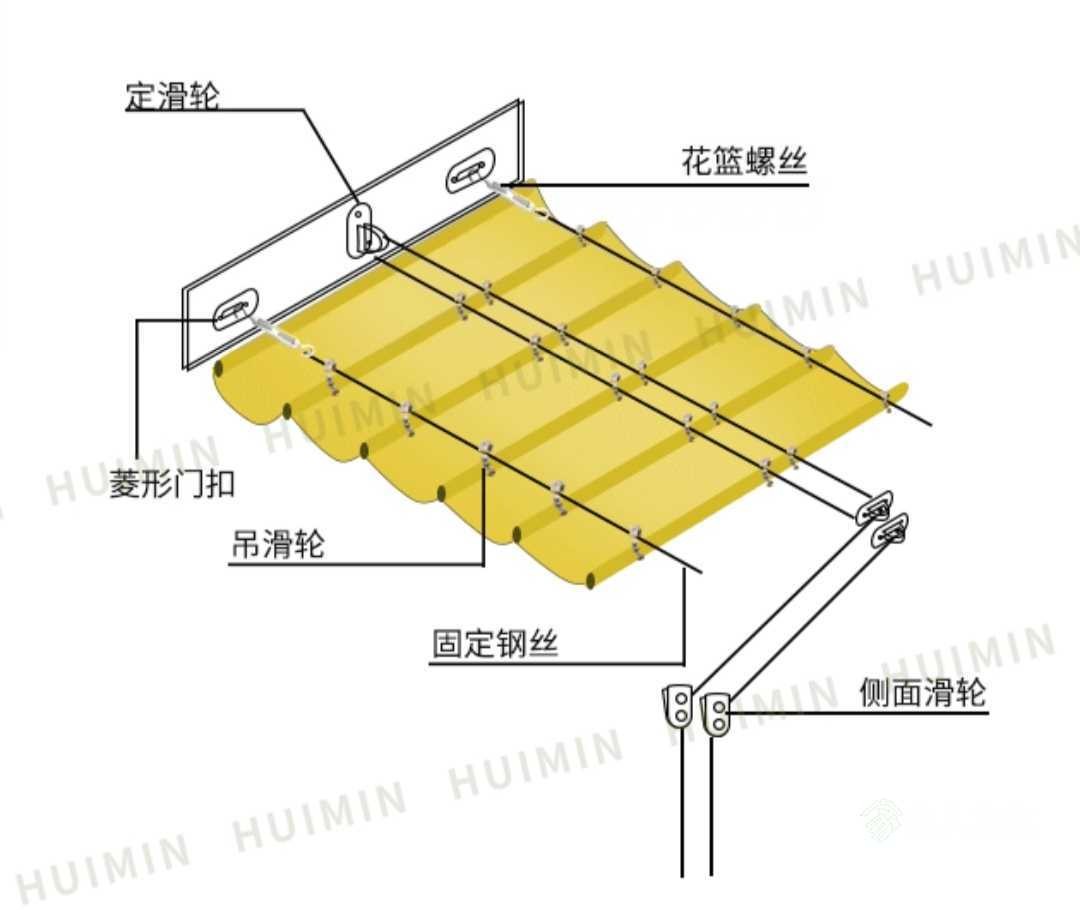
The system uses an ESP8266 as the main controller, along with an RZ7899 motor driver chip and a geared motor to pull the steel cable, thereby causing the shade net to extend and retract.
Installation diagram. I didn't take a picture of the actual installation process with my phone, but if you're interested, leave a comment and I'll take one if someone asks.
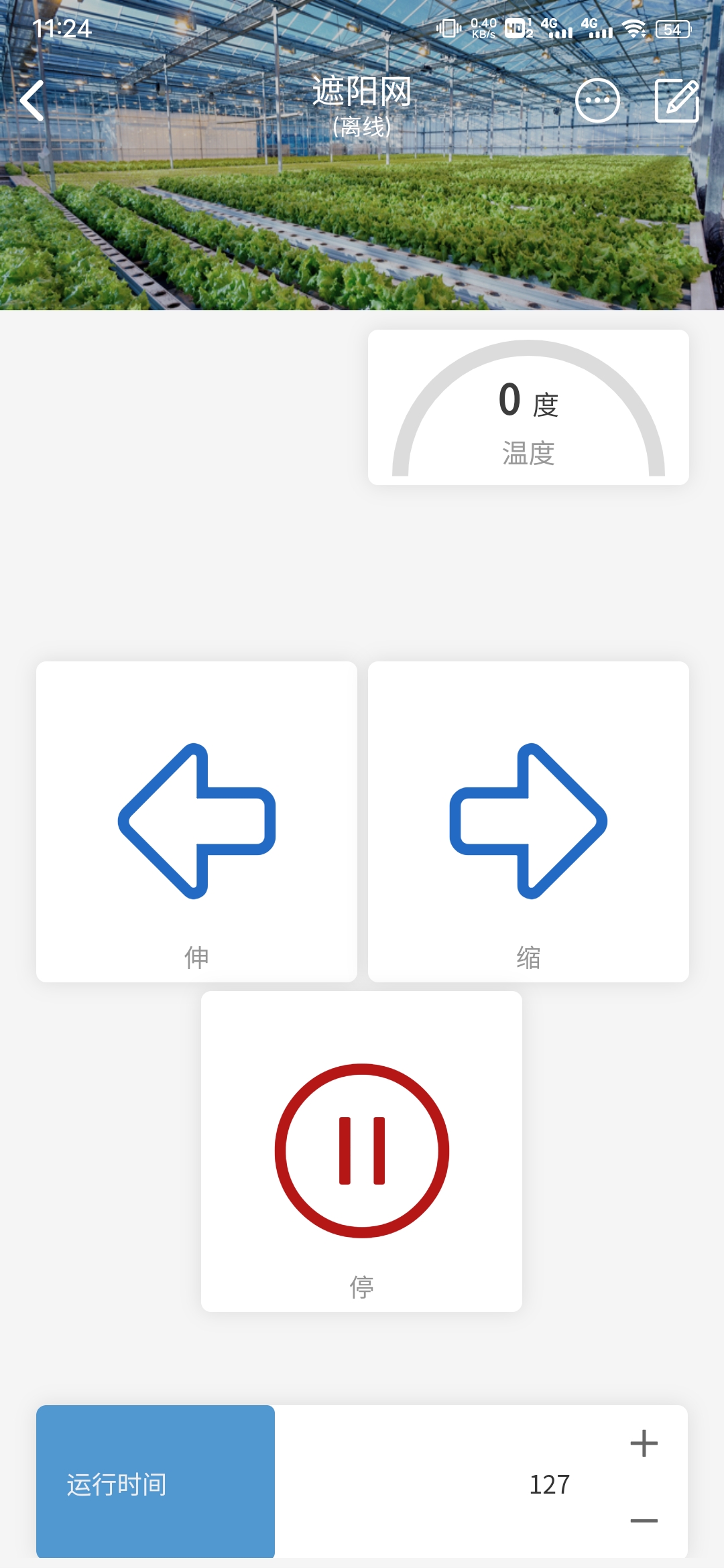
Code section:
Webpage network configuration was added. The platform used is Diandeng Technology. There's a problem with the slider code; it doesn't provide real-time refresh values. I'm too lazy to fix it.
// Key code snippets:
BlinkerButton Button1("btn-l"); // Button for turning left clockwise
BlinkerButton Button2("btn-r"); // Button for reversing the motor
BlinkerButton Button3("btn-s"); // Button for stopping the motor
BlinkerNumber TEMP("temp"); // Temperature
BlinkerSlider Slider1("sld-1"); // Slider
void motorTimerCallback() {
digitalWrite(4, LOW);
digitalWrite(5, LOW);
motorTimer.detach();
BLINKER_LOG("motorStop");
}
// Motor forward rotation
void motorForward(const String &state) {
BLINKER_LOG("get button state: ", state);
digitalWrite(4, HIGH);
digitalWrite(5, LOW);
motorTimer.detach();
motorTimer.attach_ms(motorStopInterval, motorTimerCallback);
}
//Motor reverses
void motorBackward(const String &state) {
BLINKER_LOG("get button state: ", state);
digitalWrite(4, LOW);
digitalWrite(5, HIGH);
motorTimer.detach();
motorTimer.attach_ms(motorStopInterval, motorTimerCallback);
}
//Motor stops
void motorStop(const String &state) {
BLINKER_LOG("get button state: ", state);
digitalWrite(4, LOW);
digitalWrite(5, LOW);
motorTimer.detach();
}
void heartbeat(){
TEMP.print(temp_read);
}
motor.bin
PDF_wifi Electric Sunshade.zip
Altium_wifi motorized sunshade.zip
PADS_wifi motorized sunshade.zip
BOM_wifi motorized sunshade.xlsx
95826
USB Hub Expansion Dock
Use SL2.1A to create a simple USB 2.0 extension.
When using SL2.1A and adding the USB-A port,
please note: You must add a 10uF capacitor to the 1.8V and 3.3V inputs of the SL2.1A port. I didn't add one before, which caused the chip to not be recognized.
PDF_USB_Hub Expansion Dock.zip
Altium_USB_Hub expansion dock.zip
PADS_USB_Hub Expansion Dock.zip
BOM_USB_Hub Expansion Dock.xlsx
95827
F1Clittle Mini Terminal
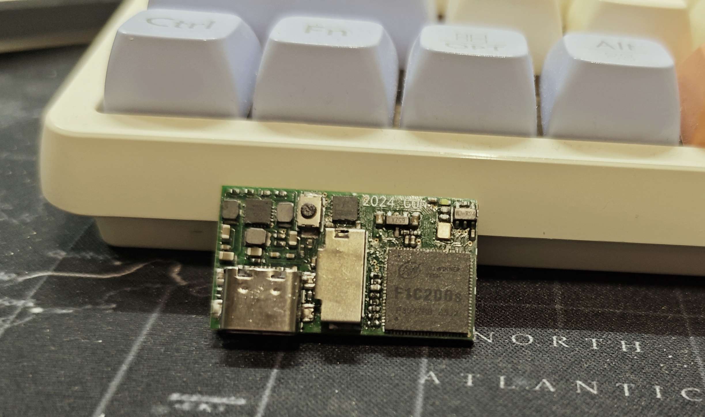
A mini terminal based on the Allwinner F1C200S, with... two peripherals! It's a very small but useless device.
This finger-sized terminal, based on the F1C200S, can be controlled via serial port and features a 1.14-inch screen and a programmable 0402 LED.
Soldering precautions:
Due to the small size of the power chip and serial port chip, it is recommended to solder the pads first before soldering the chips;
use large capacitors near the power supply interface (I personally use 22uf);
the CH343P is very close to a capacitor, so solder carefully to prevent short circuits;
the RC package is small (0402), so soldering requires care.
[Images] >>>

Regarding software, you can refer to the Lizhipai Nano (click!).
F1Clittle.eprj
PDF_F1Clittle Mini Terminal.zip
Altium_F1Clittle Mini Terminal.zip
PADS_F1Clittle Mini Terminal.zip
BOM_F1Clittle Mini Terminal.xlsx
95828
electronic


 京公网安备 11010802033920号

 2S1-MDP2-T4-B2-M7KE


