1. Equipment Description
1.1 Appearance
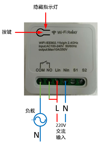
1.2 Power Supply:
100~240V AC input, Lin connects to the live wire, Nin connects to the neutral wire.
1.3 Load Connection:
The output signal is a passive relay signal, used for signal on/off control. It can handle a maximum load current of 10A. COM is the relay common terminal, NO is the relay normally open terminal, and the default state upon power-on is off.
1.4 Indicator Light Status Description:
There are three LED indicators: red, green, and blue. The corresponding device states are as follows:
Red light flashing rapidly: Waiting for network configuration Red light flashing slowly: Connected to the router, connecting to the MQTT server; Red light on: Connected to the MQTT server;
Blue light flashing once: Button pressed for more than 5 seconds;
Green light on: Relay on;
Green light off: Relay off.
1.5 Button Operation
: Short press for 1 second and release: Switch relay state;
Long press for 5 seconds: Device enters network configuration mode.
2. Function Operation
2.1 Connecting to the Wi-Fi router
requires using a mobile phone to run network configuration software. First, install the esptouch software on your phone. It only supports Android systems. Software download link: https://github.com/EspressifApp/EsptouchForAndroid/releases/tag/v2.0.0/esptouch-v2.0.0.apk
The network configuration steps are as follows:
Power on the device;
Press and hold the button for 5 seconds (release after the blue light flashes rapidly). At this time, the device enters network configuration mode;
Connect the phone to the router;
Launch the esptouch software on the phone and select EspTouch;

Enter the router password in the password box and then click confirm;
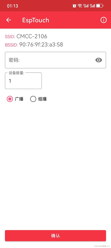
After successful network configuration, the EspTouch software will display the device's BSSID (MAC) and the LAN IP address assigned to the device by the router. You need to record the IP address for logging into the device's web management backend.

2.2 Web Management Backend
2.2.1 Login
Launch a mobile phone or computer browser on the same local area network. Enter the current device's IP address in the address bar, such as 192.168.10.103, and click to enter:
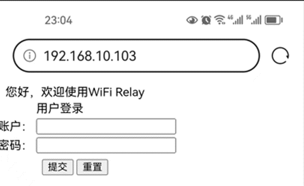
Username: admin
Default password: 123456
2.2.2 Change login password
Select the "USER" option in the directory bar:
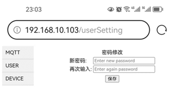
2.2.3 Configure MQTT server
Select the "MQTT" option in the directory bar:

The default server HOST: broker.emqx.io, port: 1883, is a free MQTT server that can be used for testing.
2.2.4 View device information
Select the "DEVICE" option in the directory bar:

WIFI Relay Communication Protocol - Official Version V1.5.pdf
Demo video.jpg
source code.txt
PDF_WIFI relay.zip
Altium_WIFI relay.zip
PADS_WIFI relay.zip
95922
Van Gogh Starry Night PCB
This is not color silkscreen printing, but rather an artistic artwork created using LCSC EDA's image insertion function, combining silkscreen, solder mask, and copper foil.
Color extraction code with comments is also included; you can choose your own image to create the artwork.
Bilibili video: https://www.bilibili.com/video/BV18H4y1L7UY
I saw a PCB board from The Great Wave off Kanagawa and thought it was pretty cool, so I made one myself.
Reference video for the PCB design from The Great Wave off Kanagawa: https://www.bilibili.com/video/BV1Lu411Y75b
Project link for The Great Wave off Kanagawa: https://oshwhub.com/c7h10n2/ukiyoe
I've also included the color extraction code, with comments. You can choose your own images to create your own.
The code is in the compressed file .
Requires a Python OpenCV runtime environment; the appropriate CPU version is fine.
Starry Sky.zip
PDF_Van Gogh Starry Night PCB.zip
Altium_Van Gogh Starry Night PCB.zip
PADS_Van Gogh Starry Night PCB.zip
BOM_Van Gogh's Starry Night PCB.xlsx
95923
Bluetooth console - ch9140 version
Bluetooth console cable
This project was modified based on the work of the expert Yiruhua and the schematic provided by swtbh in the comments section. Since the switch's console port lacks serial flow control, the CTS and RTS interfaces were deleted and left empty. After soldering the initial solution, the CRT tool was found to be unresponsive. Reversing the 3rd and 6th pin wiring of the network cable resolved the issue. Therefore, in this version, the SP3232 RX and TX labels were swapped, and testing confirmed it worked correctly.
PDF_Bluetooth console-ch9140 version.zip
Altium Bluetooth console - ch9140 version.zip
PADS Bluetooth console-ch9140 version.zip
BOM_Bluetoothconsole-ch9140 version.xlsx
95924
Project 3: 51 Microcontroller Development Board
This project is Project 3 of the textbook "Case Study Tutorial for Electronic Product Design (Micro-course Edition) - Based on JLCPCB EDA (Professional Edition)": 51 Microcontroller Development Board.
I. Project Introduction
Through the study and creation of the "51 Microcontroller Development Board" project case, you will become familiar with the functions and design methods of multiplexed blocks, complete the corresponding PCB design, and master the top-down and bottom-up multiplexed block design methods and bus drawing methods. Note that this circuit is not particularly complex and can be designed without using multiplexed blocks.
II. Overall Scheme
Functionally, the 51 microcontroller development board can be divided into six parts: microcontroller module, USB-to-serial port module, interface circuit module, hybrid circuit module, digital tube display module, and timer module. The connection relationships of each circuit module are shown in the system block diagram. The following uses multiplexed blocks to design and implement the circuit schematic of the 51 microcontroller development board.
Schematic

System Block Diagram

Microcontroller Module

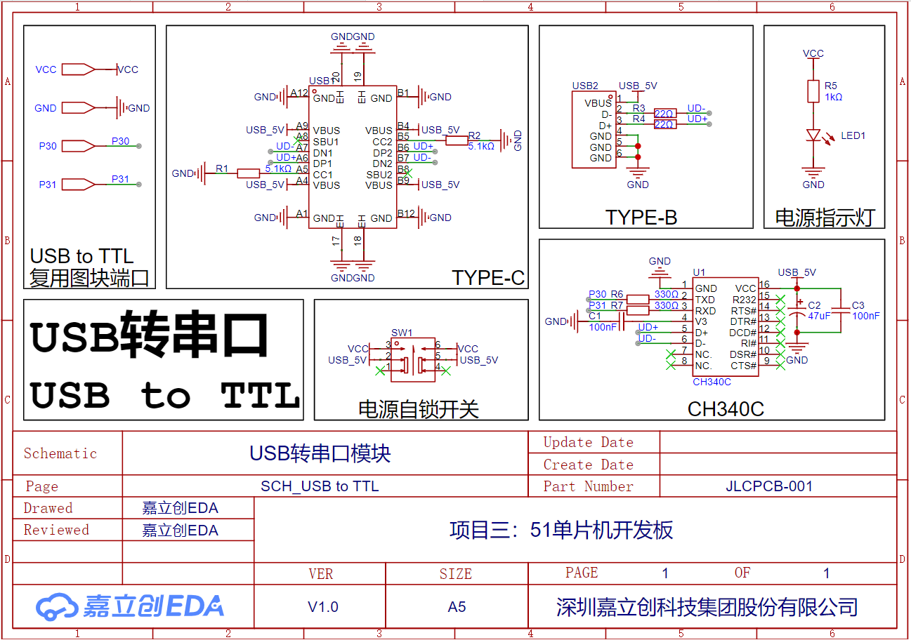
USB-to-Serial Port Module
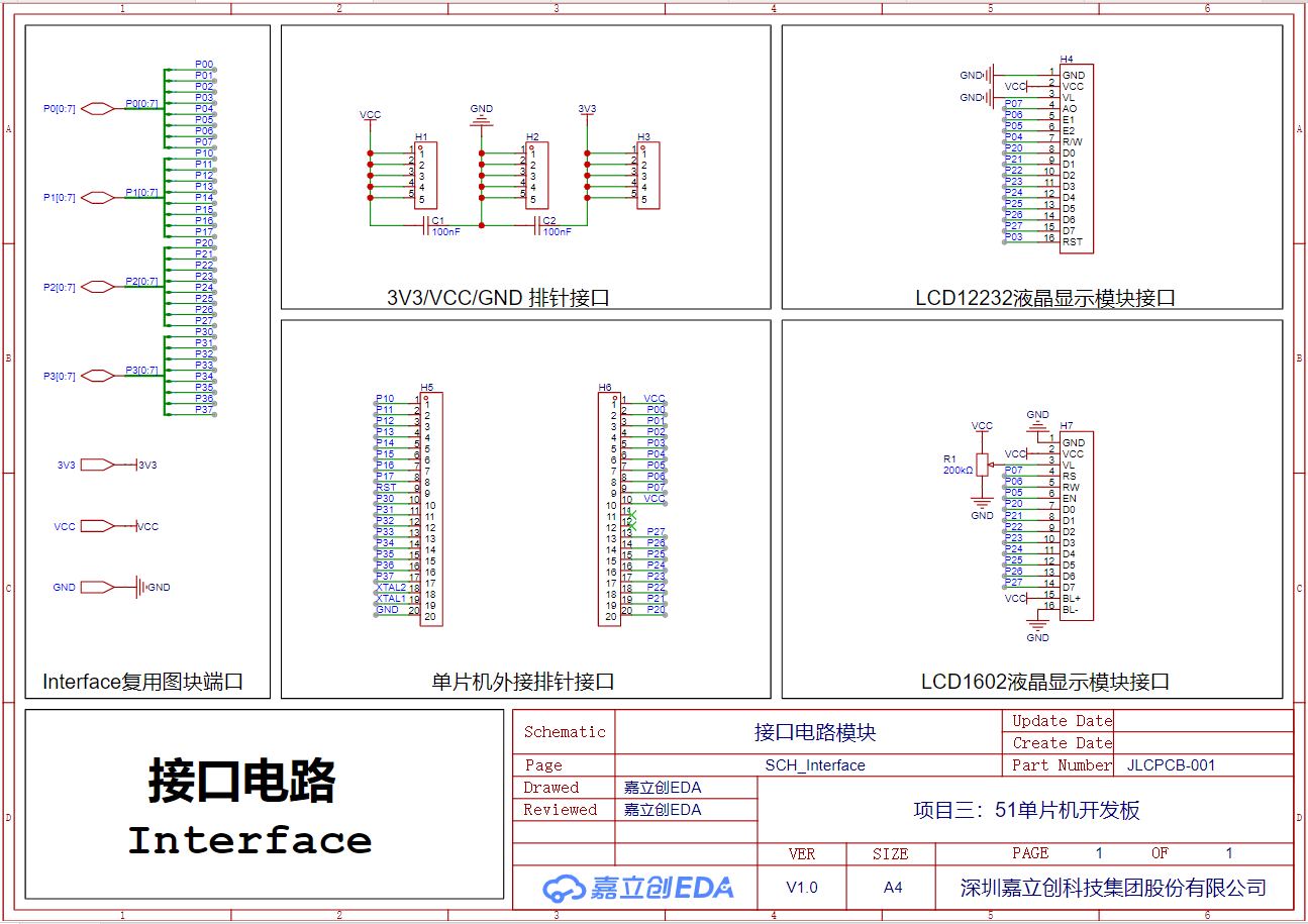
Interface Circuit Module
Hybrid Circuit Module

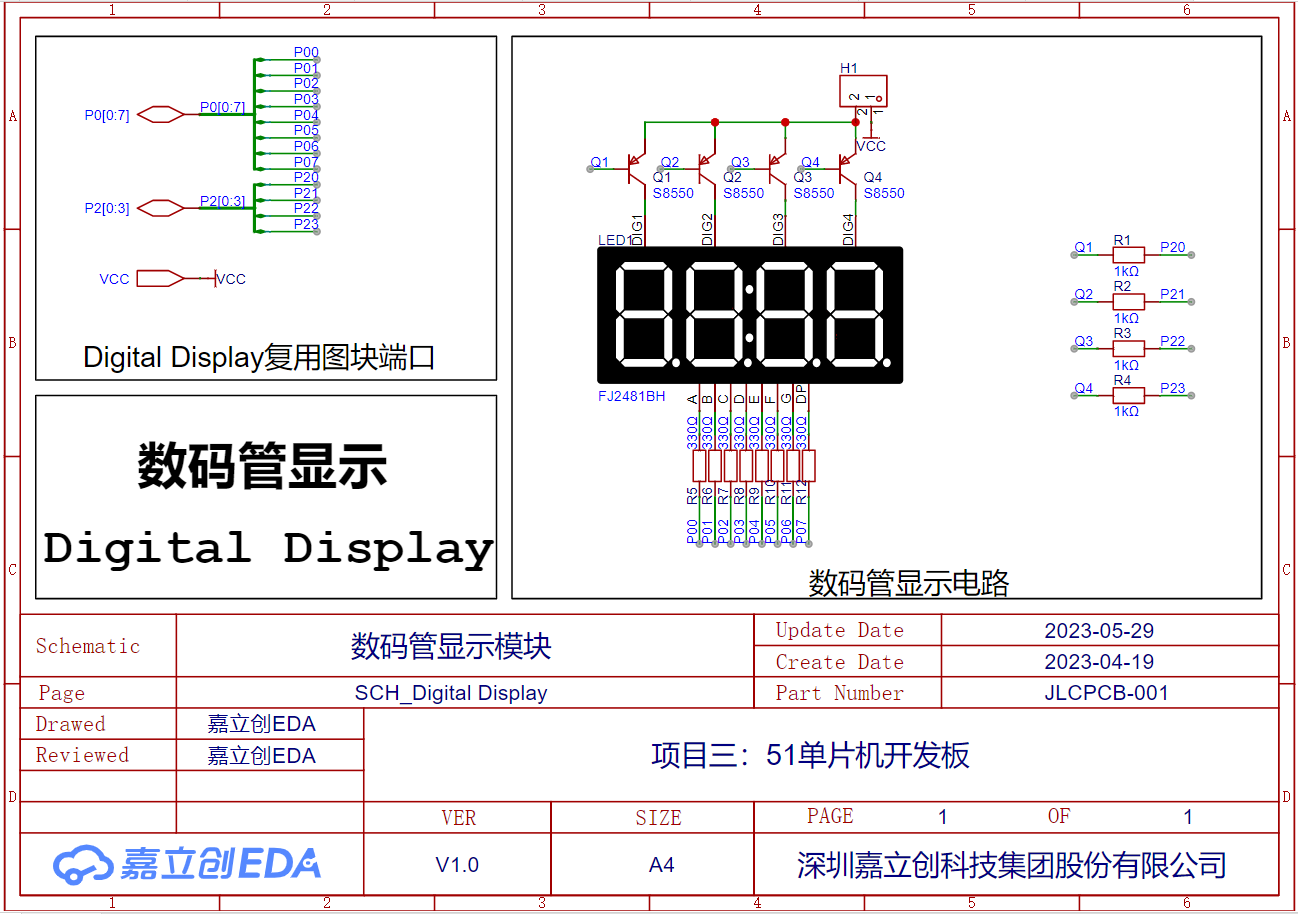
Digital Tube Display Module
Timer Module

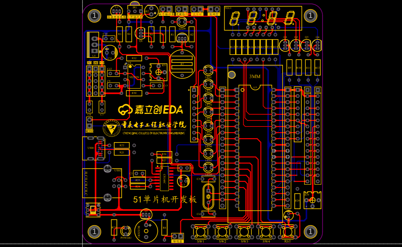
PCB
3D Rendering

Actual Image

Bill of Materials.xlsx
PDF_Project 3: 51 Microcontroller Development Board.zip
Altium_Project 3: 51 Microcontroller Development Board.zip
PADS_Project 3: 51 Microcontroller Development Board.zip
BOM_Project 3: 51 Microcontroller Development Board.xlsx
95925
electronic


 京公网安备 11010802033920号

 FX-104-CFC-D4M8


