You can test the data cable, but please note: do not unplug the power cord while it's plugged into the test terminal, otherwise it will cause a short circuit.
The image below shows the initial test setup with corrections; the PCB circuit has been corrected.

PDF_Data Cable Tester.zip
Altium_DataCableTester.zip
PADS_Data Cable Tester.zip
BOM_Data Cable Tester.xlsx
96111
mini-cassette-smt
The panel for this project
is available at https://oshwhub.com/jd3096/mini-cassette-player_copy_copy
Original project address:
https://oshwhub.com/jd3096/mini-cassette-player_copy_copy
Suggested order configuration:
Opaque bottom printing, 0.8mm thickness.
PDF_mini-cassette-smt.zip
Altium_mini-cassette-smt.zip
PADS_mini-cassette-smt.zip
96112
SEPIC boost/buck converter of LM3478 and BOOST boost converter of HT7179
Verification boards for the SEPIC buck-boost circuit based on LM3478 and the BOOST boost circuit based on HT7179.
This project presents a verification board based on the LM3478-based SEPIC boost/buck circuit and the HT7179-based BOOST boost circuit
, along with a 3.3V buck circuit to power the microcontroller
(the following is excerpted from the LM3478 and HT7179 datasheets)
. The LM3478 is a multi-functional low-side n-channel MOSFET switching regulator controller. It is suitable for topologies requiring low-side MOSFETs, such as boost, flyback, and SEPIC.
VIN: 2.97V-40V.

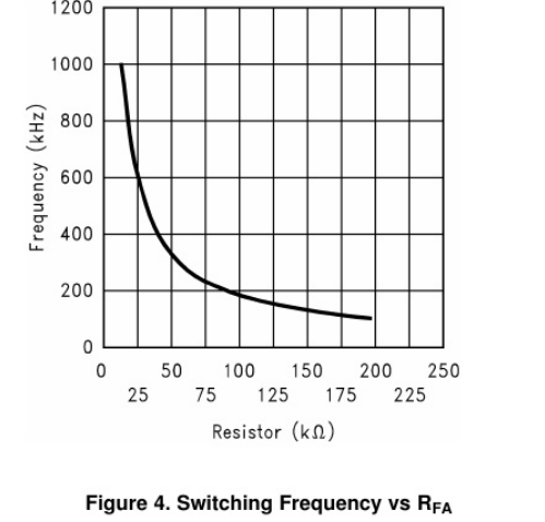
The switching frequency of the LM3478 can be adjusted between 100 kHz and 1 MHz using a single external resistor. This resistor must be connected between the FA/SD pin and ground.
RFA = 4.503 × 10^-11 × fS^-1.26.
The HT7179 is a high-power asynchronous boost converter with an integrated 20mΩ power transistor.
VIN: 2.7V-25V
VOUT: 26.8V (max)
Fixed switching frequency: 350kHz
Programmable peak current: 15A (max).
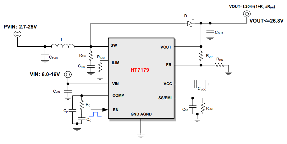
The peak current limit of the HT7179 can be set by connecting a resistor to ground via the ILIM pin. As shown in the diagram , this

is my first attempt at this project, and there are many errors and non-standard aspects. Please feel free to point out any mistakes.
HT7179.pdf
lm3478.pdf
tps5430.pdf
PDF_LM3478 SEPIC Boost/Buck and HT7179 BOOST Boost.zip
Altium_LM3478 SEPIC Boost/Buck and HT7179 BOOST Boost.zip
PADS_LM3478 SEPIC Boost/Buck and HT7179 BOOST Boost.zip
BOM_LM3478 SEPIC Boost/Buck and HT7179 BOOST Boost.xlsx
96117
Speed-adjustable smoke exhaust fan bracket
A discarded hair dryer fan was modified into a simple solderable exhaust fan, compatible with other brushed DC motors.
This is the V2.0 version of a modified old hair dryer speed-adjustable exhaust fan.
The previous version used wired power, which was inconvenient as it occupied multiple power outlets and power banks didn't always provide 12V.
Therefore, version 2.0 adds an 18650 lithium battery power supply with protection and automatic switching . It uses
an SX1308 boost converter for 12V
and features colorful silkscreen printing, making it very attractive and even eliminating the need for a separate casing.
Version 1.0 used
a low-cost
CH224K decoy power supply + DC power for 12V
speed control, directly utilizing an on-board
PWM DC motor speed controller 2A speed switch module
1.8-12V adjustable switch speed control board.
PDF_Adjustable Speed Exhaust Fan Mount.zip
Altium_Adjustable Speed Exhaust Fan Mount.zip
PADS_Adjustable Speed Exhaust Fan Mount.zip
BOM_Adjustable Speed Exhaust Fan Mount.xlsx
96118
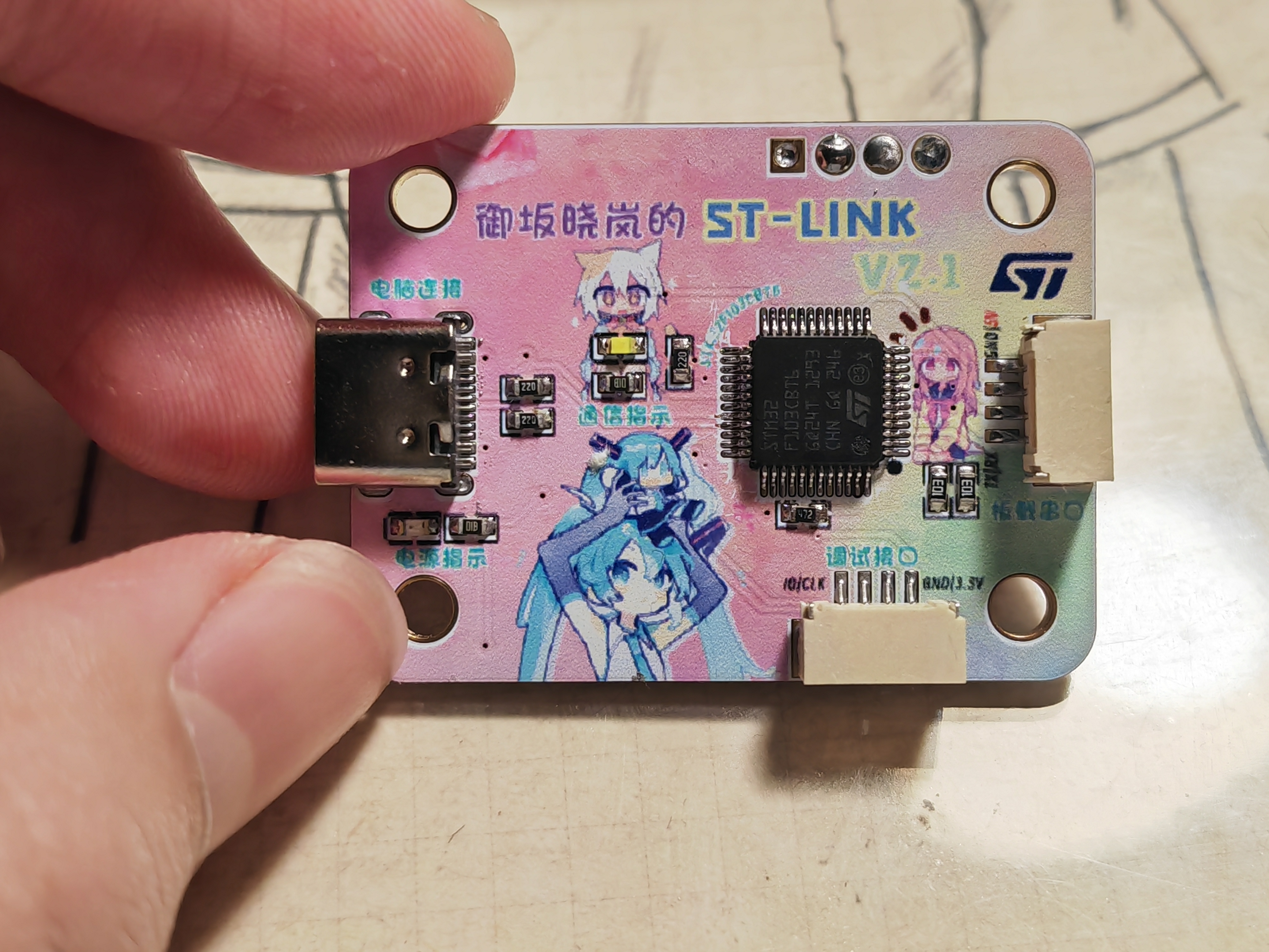
[Color Screen Printing] Homemade STLink V2.1
The STlink phones on Taobao were too difficult to use; they could only be plugged directly into the computer, required manual wiring, and had inconsistent interfaces. So, in a fit of frustration, I designed a new STlink. Using color silkscreen printing technology, I designed a background image that conforms to PCB layout—it's both attractive and easy to use!
This is my first open-source project. If you like it, don't forget to like and bookmark it!
Click "Open with Editor" in the upper right corner to browse the project!
Have you encountered the following problems when using ST-Link:
the four-pin SWD debugging interface is inconsistent with the ST-Link interface, requiring repeated wiring comparisons;
ST-Link can only be plugged directly into USB, resulting in poor mobility;
DuPont wires are prone to falling off after prolonged plugging and unplugging, requiring frequent replugging;
there is no integrated serial port, requiring an additional,
unsightly module for serial debugging!
This ST-Link design aims to solve these pain points!
Here are some pictures of the finished product:

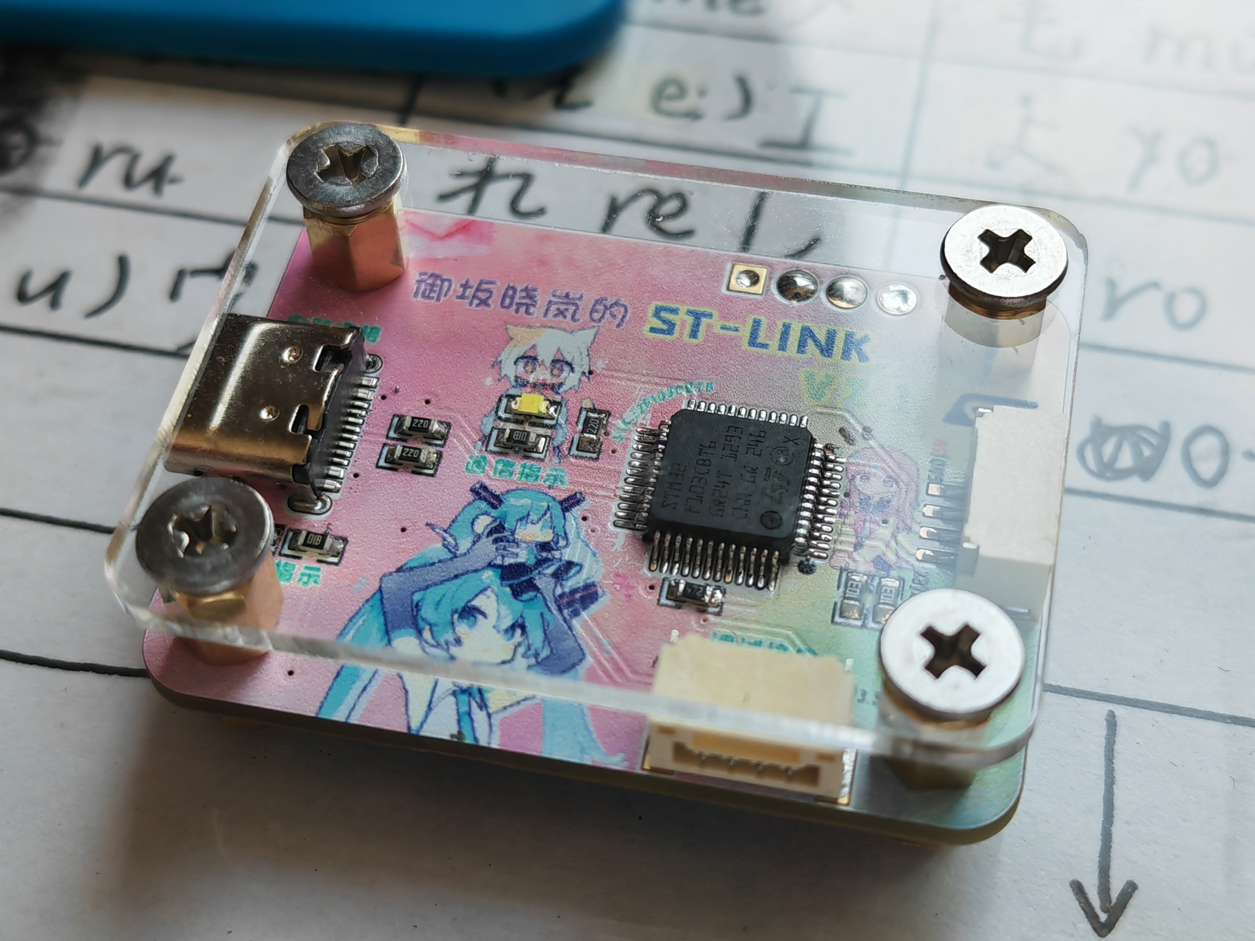
It can be used with an acrylic shell for easier handling and a more premium feel.
Design features:
It uses JLCPCB color silkscreen printing technology, making it exquisite and cute!
It uses a Type-C interface, allowing for connection with a data cable of any length!
All interfaces use the GH-1.25mm standard connector with built-in anti-drop clips, ensuring it stays in place even after prolonged use and can be dragged freely!
It can be paired with copper pillars and an acrylic plate for stable placement, preventing hand sweat, and can also be used for display!
This system uses ST-Link V2.1, with an onboard serial port. A single USB interface allows for both debugging and downloading, as well as simultaneous serial port simulation!
A background PSD source file is provided, allowing you to freely modify text and elements!
Important Notes:
For the connectors, you can directly purchase a GH1.25mm to DuPont wire adapter cable on Taobao; it's very inexpensive. For
the copper pillars, you'll need to purchase M3*4 hexagonal copper screws, M3*5+4 hexagonal copper pillars, and M3*4 flathead screws (we strongly recommend installing the copper pillars so the board can rest flat on a table without damaging components). For
the acrylic board (optional), search for "acrylic customization" on Taobao; you can buy more than 10 pieces for about 6 RMB.
You must have a working ST-Link device; the version doesn't matter. After soldering, you need to program the board using an existing ST-Link.
You must select STM32F103CBT6; otherwise, there won't be enough FLASH space to program it.
Programming Tutorial:
A standard 4-pin SWD debugging point is provided at the top of the board. No soldering is required. You can insert DuPont wires into the pads and press all four wires against the inner wall with your fingers (because the pads are gold-plated and the inner wall is conductive). This will allow you to program the device. If you're unsure how to do this, solder them temporarily and remove them after programming.
The zip package includes an ST-LINK Utility installer; install it.
Connect the four contacts, then insert your existing ST-Link. Follow the image instructions to connect the target device, import the file (the bin file in the zip package), and program (default options are fine).
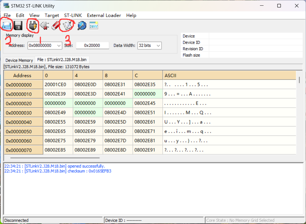
After successful programming, disconnect all cables and connect the new ST-Link to your computer using a Type-C cable. Your computer should automatically recognize the ST-Link. If it doesn't, try installing the driver included in the zip package.
Feel free to leave a comment or add QQ 1806065098 if you have any questions!
ST-Link.zip
Cover source file.zip
Acrylic sheet drawing.DWG
PDF_【Color Silkscreen】DIY STLinkV2.1.zip
Altium_【Color Silkscreen Printing】DIY STLinkV2.1.zip
PADS_【Color Silk Screen Printing】DIY STLinkV2.1.zip
96120
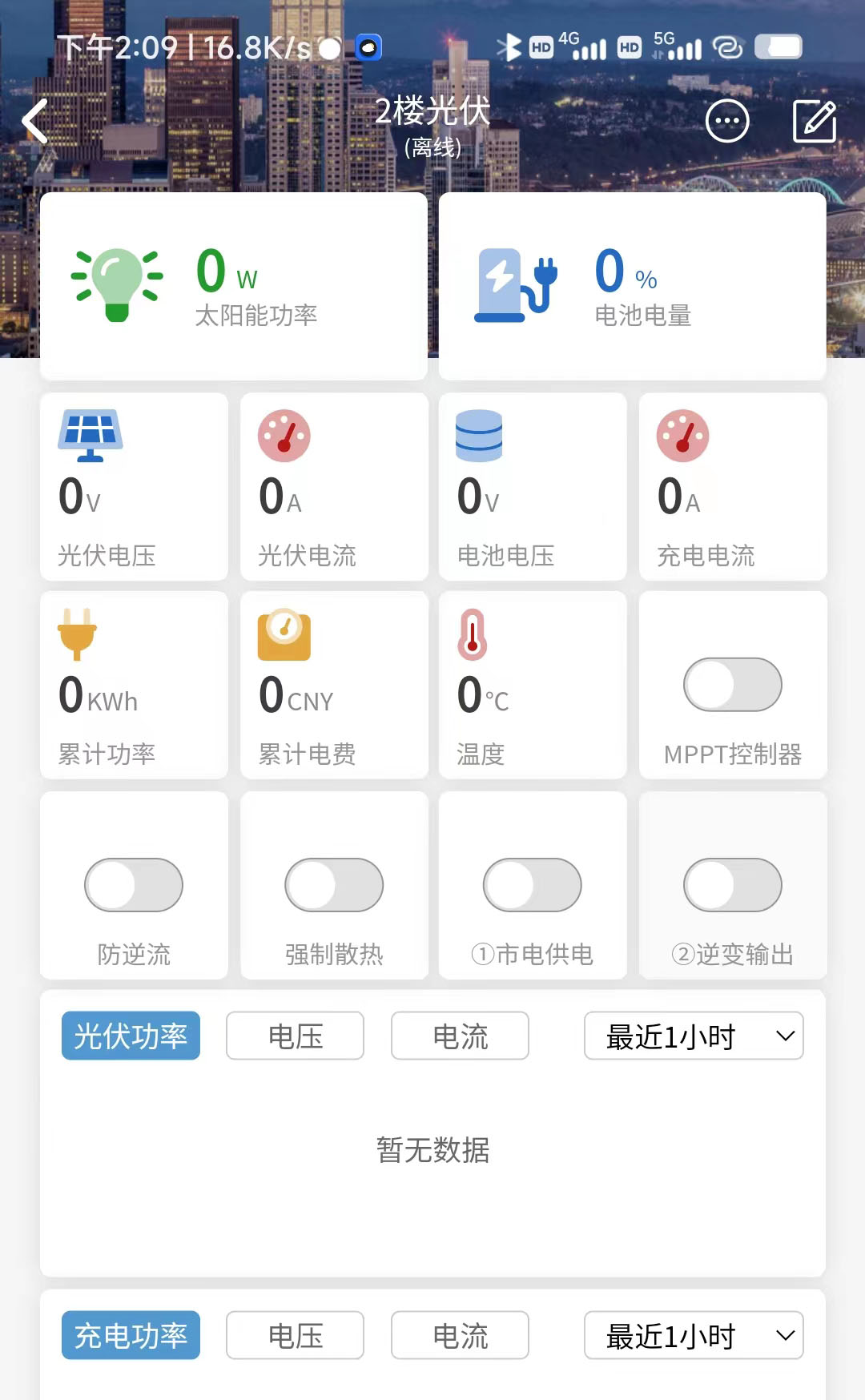
[Tested] MPPT96V35A Automatic Lifting Controller
It supports MPPT or digital power controllers, uses H-bridge automatic buck-boost, can limit the minimum input voltage, and comes with 2 output controls that can automatically turn on or off based on time or battery voltage.
【Basic Parameters】 Input Voltage: 9 - 96V Output Voltage: 1.2 - 96V Output Current: 0 - 35A
Display: 1.8-inch TFT
Mobile Terminal: Lighting APP
supports WIFI network configuration, solar MPPT disturbance algorithm mode, overcurrent and reverse current protection. This product was made in my spare time. If you have any questions, please provide feedback in the group.
This open-source product is for personal DIY use only and may not be sold or used for commercial purposes without permission.
QQ Discussion Group: 483012638
【Update Log】
20240203 Added C2 version for higher work efficiency
20231015 Updated to EG3112 for more stable operation
20230902 Based on feedback, optimized power supply, added LDO, widened some wiring, tested normally:
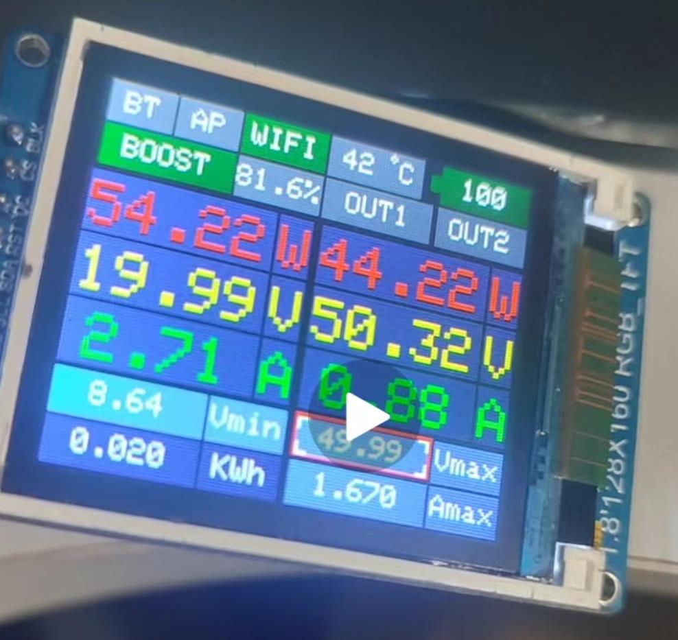
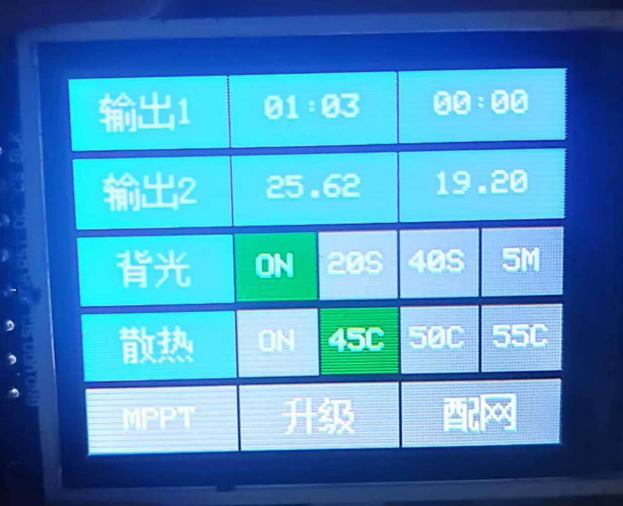
Operation screen:

Lighting APP: Front of
experimental board:
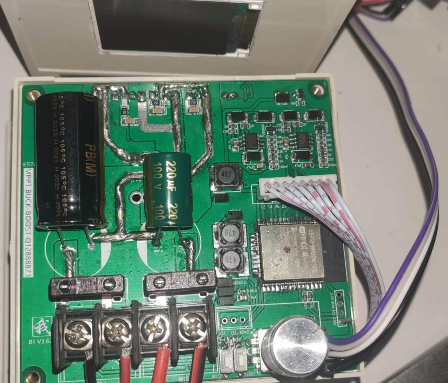
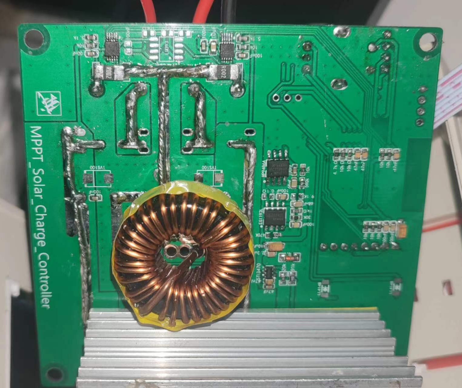
Back of experimental board:
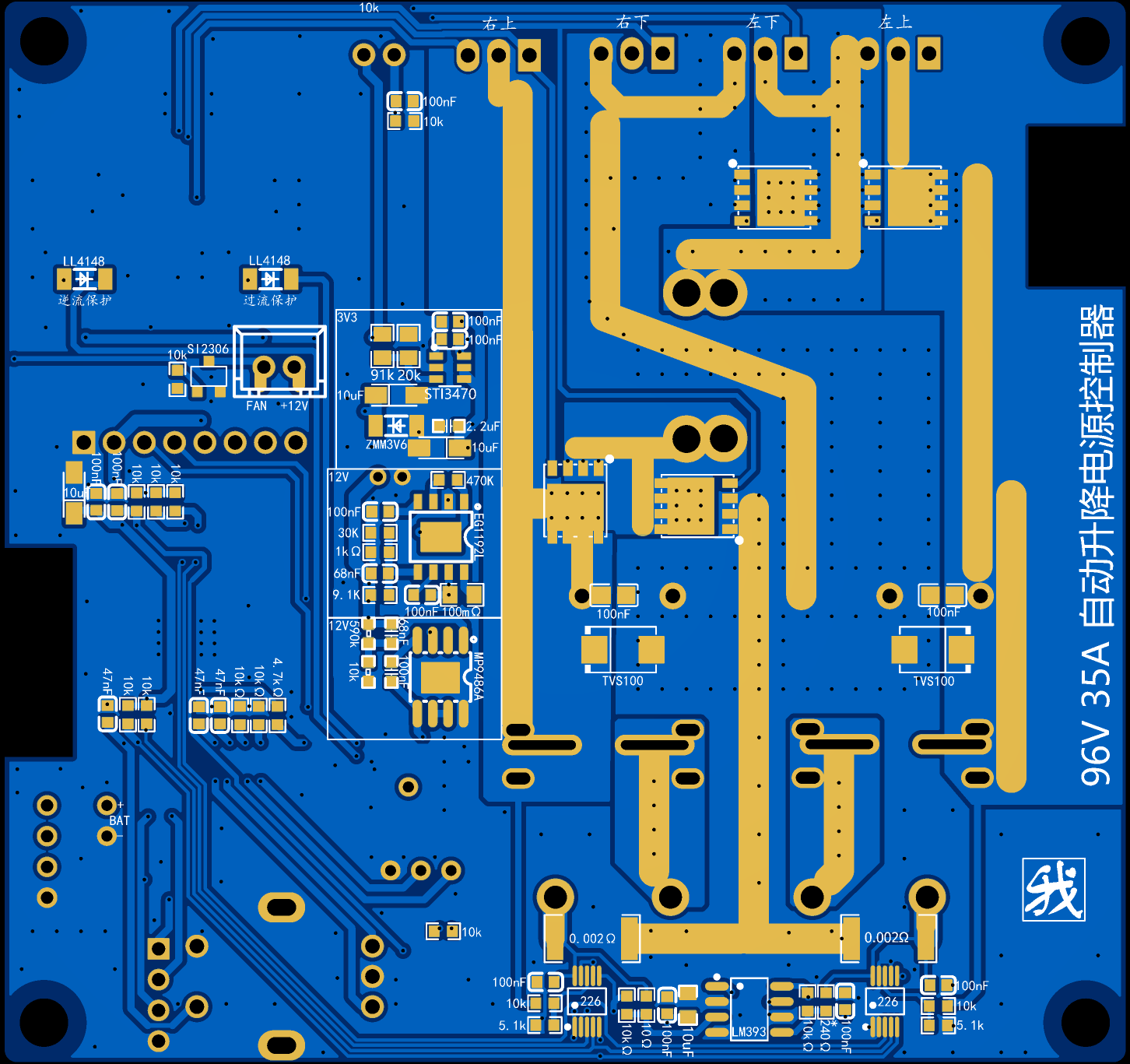
Front of simulation diagram:

Back of simulation diagram:
Blinker Configuration_blinker_UI.txt
readme.txt
PDF_【Tested】MPPT96V35A Automatic Lifting Controller.zip
Altium_ [Tested] MPPT96V35A Automatic Lifting Controller.zip
PADS_【Tested】MPPT96V35A Automatic Lifting Controller.zip
BOM_C1_MPPT_4MOS_Digital Power Supply_Automatic Buck-Boost_Classic Edition.xlsx
96122
electronic


 京公网安备 11010802033920号

 1200JG6F004B3EA


