This
is a serial port programming tool based on CH340C, capable of automatic downloading to the Heze Air001 chip. Given the price of the Air001 chip, integrating the automatic download circuit into the overall circuitry is somewhat extravagant; a separate programmer is more cost-effective
.
The automatic download circuit design is referenced from the [Air001 Development Board Schematic](https://wiki.luatos.com/chips/air001/hardware.html). However, because its design differs from other automatic download circuits, its universality cannot be guaranteed.
|
Front | Back |
| :-: | :-: |
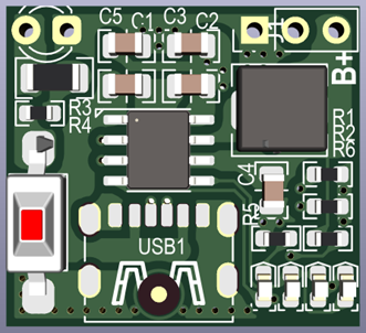
| ![photo_01.png]
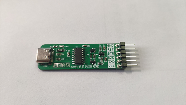
works better when used with [Test Clip_Probe_Open Source](https://oshwhub.com/zhigao1986/ce-shi-jia-_-tan-zhen_copy)
![photo_02.png]

PDF_Air001 Auto Downloader.zip
Altium_Air001 Auto Downloader.zip
PADS_Air001 Auto Downloader.zip
BOM_Air001 Auto Downloader.xlsx
96185
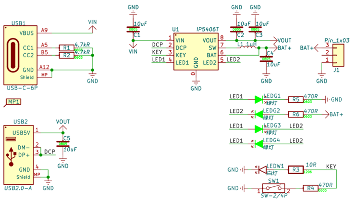
IP5406T 10W Power Bank (PK IP5306)
The IP5406T supports 2A charging and 2.4A discharging.
It is a power bank SOC chip suitable for single-cell batteries, and a replacement for the traditional IP5306 chip.
The
IP5406T supports 2A charging and 2.4A discharging.
It is a power bank SOC chip suitable for single-cell batteries, and a replacement for the traditional IP5306 chip.
Input voltage
is 4.65~5.6V. 4.65V trigger undervoltage protection, automatically reducing charging power
output voltage
4.2/4.35V
trickle charging
2.7V, trickle current 250mA,
full charge cutoff
VIN
LED
4 LED indicator
night light
long press to trigger, long press to turn off
NTC
does not support
chip over-temperature
built-in over-temperature protection, 150℃
standby power consumption
USB voltage
USB current
Battery voltage
Battery current
Charging power
Charging efficiency
4.97V
1.945A 3.85V
2.30A
8.86W
91.7
%
4.97V
1.946A
3.98V
2.22A
8.84W
91.4%
4.97V
1.948A
4.15V
2.15A
8.92W
92.1%
USB voltage
USB current
Battery voltage
Battery current
Discharge power
Discharge efficiency
5.075V
2A
4.205V
2.60A
10.94
92.9%
5.074V
2A
4.103V
2.676A
10.98W
92.5%
5.074V
2A
3.897V
2.837A
11.06W
91.8%
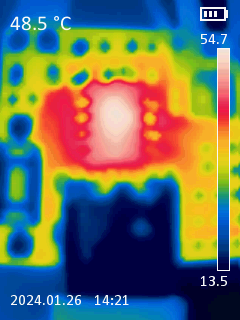
Charging (left), Discharging (right) Temperature
Schematic Diagram
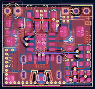
PCB Layout Diagram
PCB 3D Preview
PCB Physical Image

Data Download
Other design files in other formats can be obtained from your supplier.
Demo-IP5406T_V0.1_BOM_240126.csv
Demo-IP5406T_V0.1_Gerber_240126.zip
IP5406T datasheet _cn_V1.0.pdf
PDF_IP5406T 10W Power Bank (PK IP5306).zip
Altium_IP5406T 10W Power Bank (PK IP5306).zip
PADS_IP5406T 10W Power Bank (PK IP5306).zip
BOM_IP5406T 10W Power Bank (PK IP5306).xlsx
96189
PC remote power-on card
Multifunctional remote computer power-on card
I recently assembled a computer using an x99 motherboard and found that after the motherboard is shut down normally, the PCIE slots and USB ports have no power. When the computer is shut down normally, the power-on function does not work. The only way to wake up the machine is with the wired network card. However, I never considered setting up a wired network for the computer. So I decided to make a remote power-on card myself and make it more versatile and have more functions.
The functions are as follows:
Supports external USB power supply (suitable for motherboards where the PCIE slots and USB ports cannot continue to supply power after shutdown)
Supports external deployment (no need to open the case and study the PCIE slots): It can be plugged into the computer's wired network port (if the computer is shut down, it supports wired network card wake-up) or plugged into the computer's USB port (if the computer is shut down, the USB port can still supply power)
Supports three power-on methods: (1) wired network card wake-up; (2) USB wake-up; (3) power jumper power-on (the jumper needs to be introduced into the case);
After the computer is powered on, the device will automatically turn into a wireless network card to provide wireless network for the computer. (Due to the limitations of the electronic components used, the network bandwidth does not exceed 100Mbps)
After the computer is turned on, the device can communicate with the program inside the computer, collect key information about the computer's hardware and software, and display it on the mobile phone's app.
PDF_PC Remote Power-On Card.zip
Altium_PC Remote Power-On Card.zip
PADS_PC Remote Power-On Card.zip
BOM_PC Remote Power-On Card.xlsx
96190
New Year RGB Light Board
ESP32C3 controls RGB LED strings via WS2812, WLED debugging software.
I. Preparation:
Setting up the computer environment:
1. JLCPCB EDA Web Professional Edition (circuit diagram design).
2. WELD Web Page (code debugging).
Resources: Reference: [LCPCB Panel Printing] Engraved Standee Night Light + Open Source | ESP32C3 Temperature and Humidity Sensor AHT20 + SHT30
II. Code Debugging and Firmware
Burning:
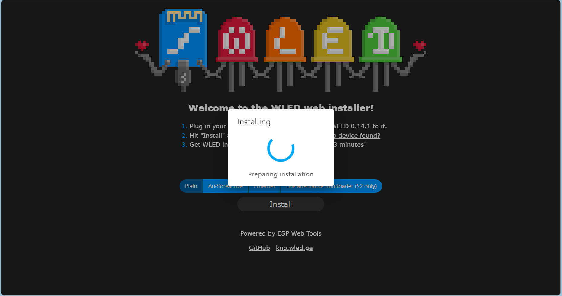
1. Access the website and click Install:
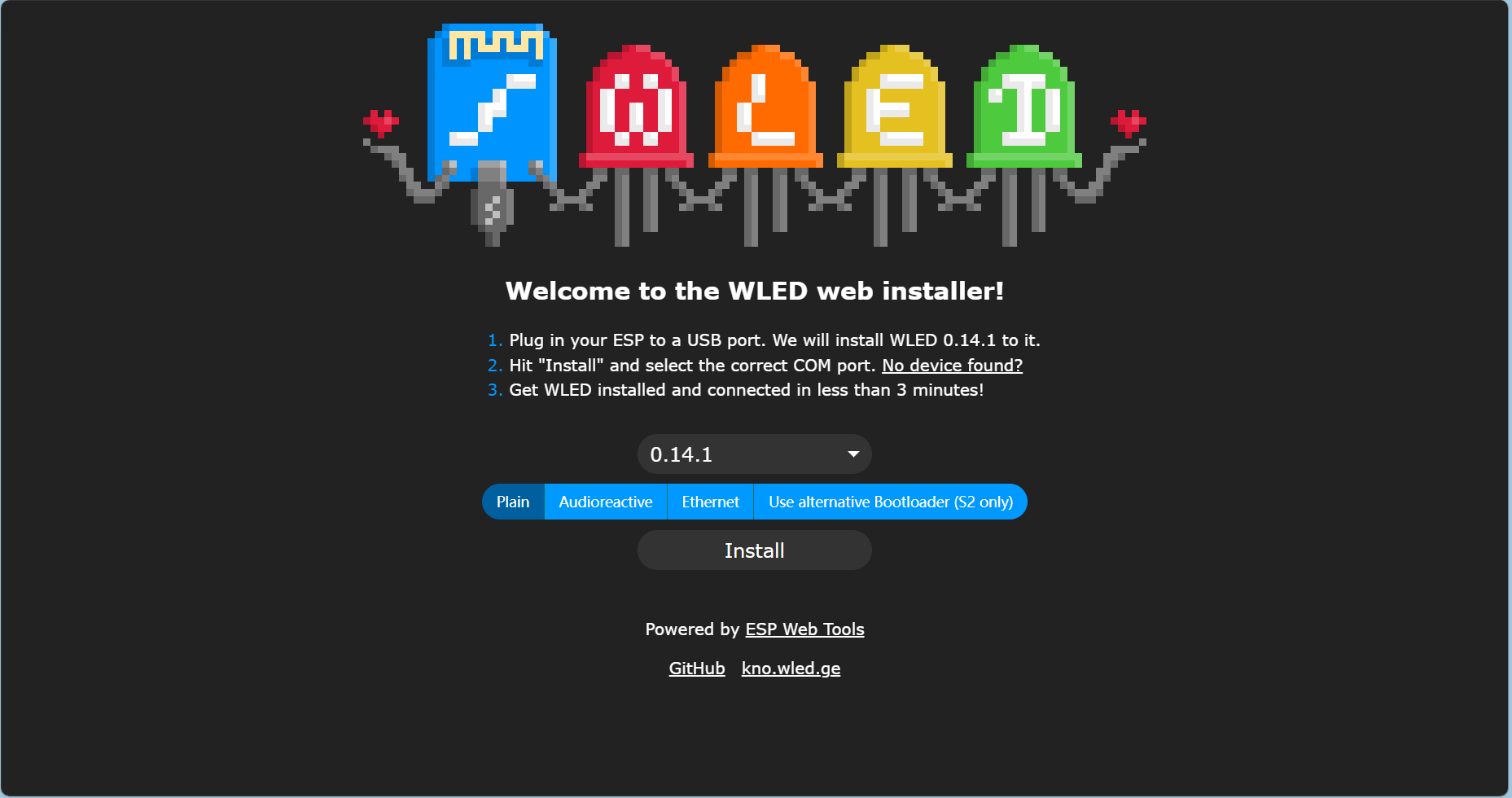
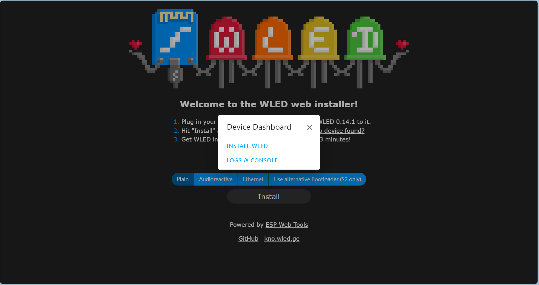
2. Connect to the COM port:

3. Select INSTALL WLED:
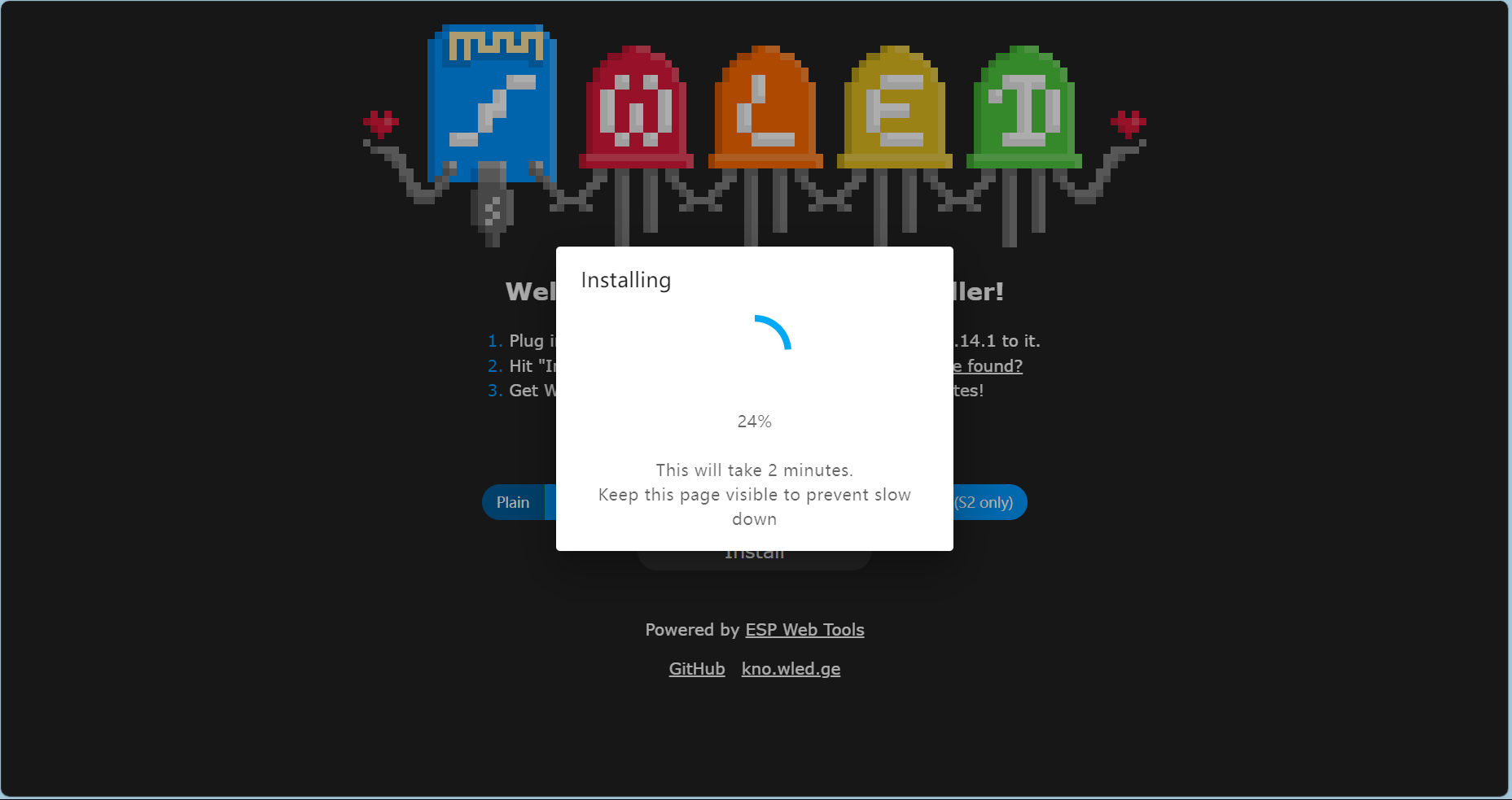
4. Click INSTALL:
Clicking INSTALL will delete all existing data on the development board.
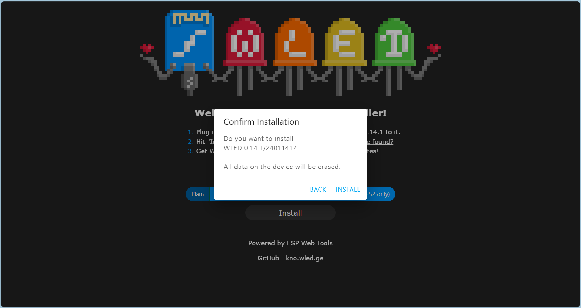
5. Browser automatic installation: Preparing to install -> Installing -> Installing... -> Installation successful


Mobile debugging parameters:
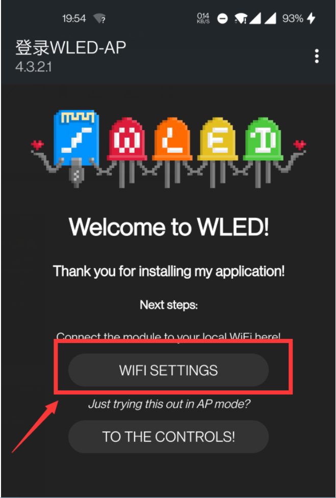
1. Turn on Wi-Fi and connect to the WLED-AP's Wi-Fi, password: wld1234. A webpage will automatically open for Wi-Fi configuration. Select WIFI SETTINGS to configure Wi-Fi. Alternatively, you can directly click TO THE CONTROLS below to control Wi-Fi.
2. Enter your home Wi-Fi name and password, then click Save & Connect on the upper right to save the configuration.

3. At this time, you can see the IP address of WLED from the router management interface. Enter the address in your browser. Click Config.

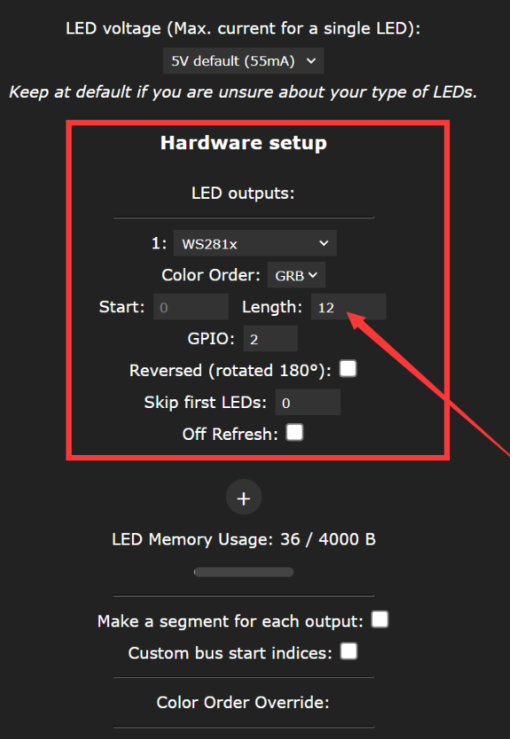
4. Click LED Preferences and change the number of LED beads to your actual number. Then click Save at the bottom to save the configuration.
IV. Problems and Countermeasures
Hardware:
1. ch340K cannot be fully adapted.
2. GPIO2 and GPIO9 should be pulled up.
3D shell:
Simple shell, no openings, no fixing screws.
Improvement: PCB fixing studs are combined with the shell for fixing.
V. Summary and
Improvement Space:
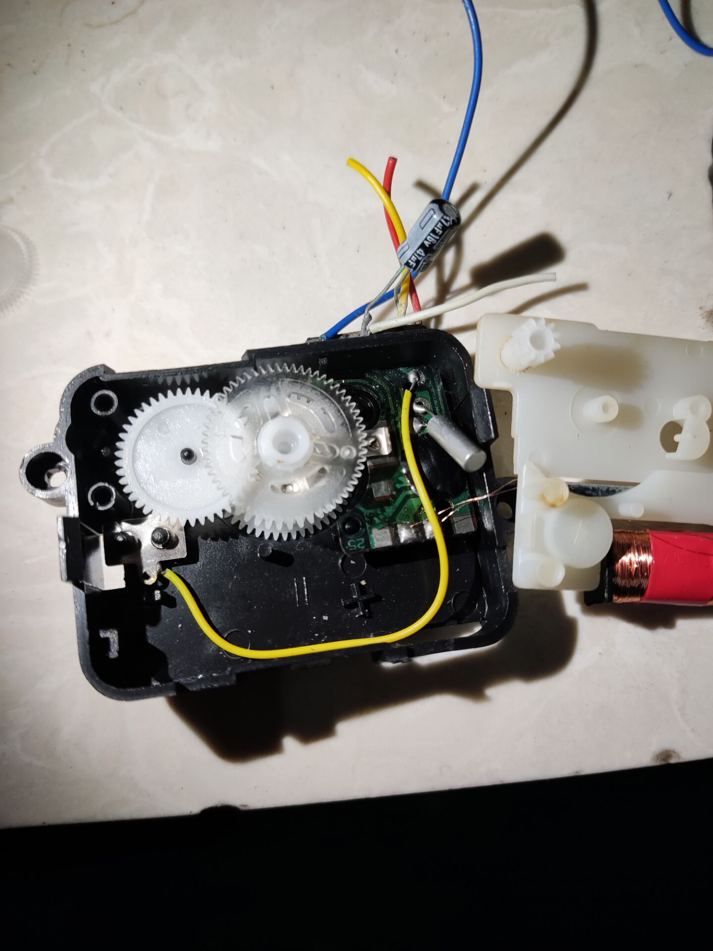
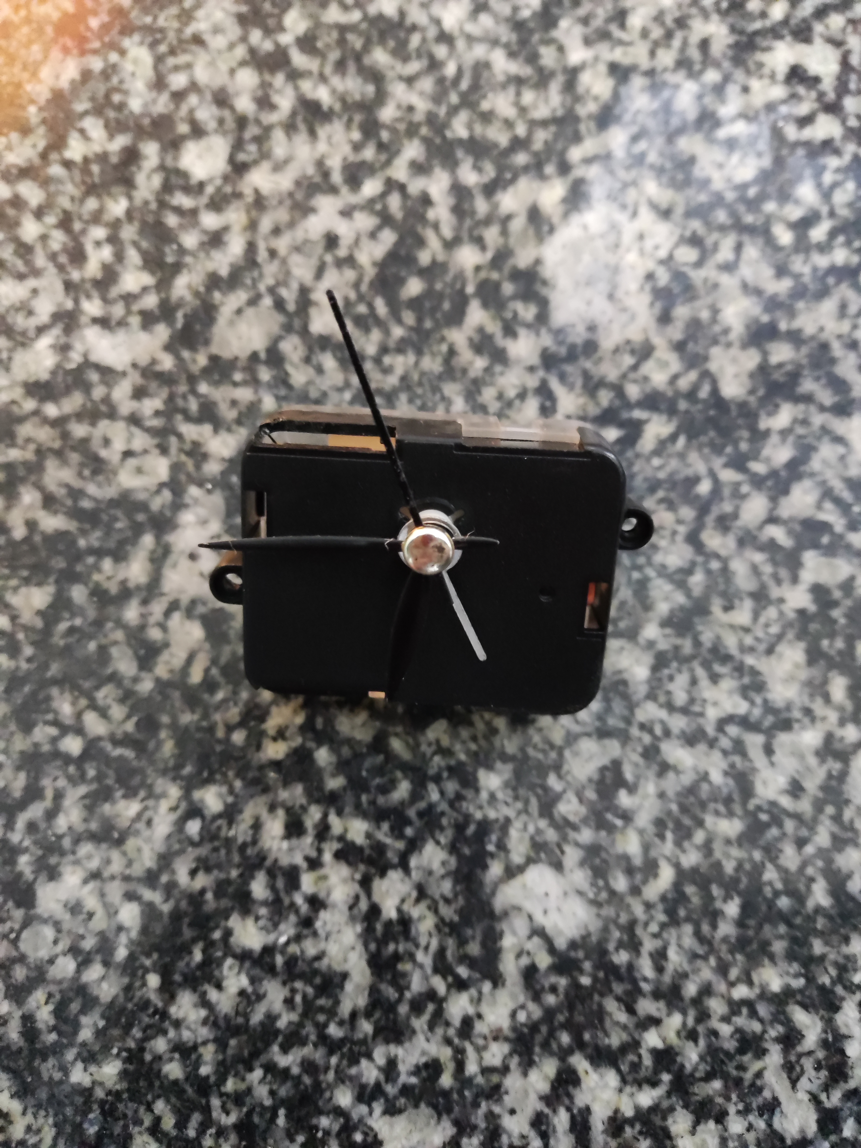
(1) Add clock function (waste utilization: measure how the voltage and frequency of the old electronic alarm clock drive the electromagnet to control the gear to rotate accurately).
(2) Can be changed to IoT applet control.
(3) Improve the external mirror film
. Refer to the 8-inch light painting EPS12F+WS2812-replace LED beads.
Unnamed Draft.mp4
PDF_New Year RGB Light Board.zip
Altium_New Year RGB Light Board.zip
PADS_New Year RGB Light Board.zip
96192
Warm Winter AI Voice Atmosphere Assistant
The project's design primarily utilizes the Unisound offline AI voice chip as the main controller.
1. It serves as a fun decorative item for smart home applications, perfect for winter.
2. It can be paired with Tmall Genie to create a smart desk.
The project's design primarily utilizes the Unisound offline AI voice chip as the main controller.
1. It serves as a fun decorative item for smart home applications, perfect for winter.
2. It can be paired with Tmall Genie to create a smart desk.
WeChat_20240129220438.mp4
PDF_Warm Winter AI Voice Atmosphere Assistant.zip
Altium_Warm Winter AI Voice Atmosphere Assistant.zip
PADS_Warm Winter AI Voice Atmosphere Assistant.zip
BOM_Warm Winter AI Voice Atmosphere Assistant.xlsx
96193
electronic


 京公网安备 11010802033920号

 1N4730UR-1E3


