Project Musings:
In my freshman year, as a team member, I participated in the National Robotics Competition with senior students and won a national first prize (11th place nationwide). At that time, I was still a newbie following along with the senior students, doing wiring, layout, soldering, and playing with oscilloscopes and load meters. In my sophomore year, as a key member and the leader of the hardware group, I participated in RoboCon and won a national first prize (this time, 5th place nationwide!!!). At this point, I was promoted to a big newbie, haha. I especially remember going to Nanjing University of Science and Technology during the summer to participate in the RoboCon National Robotics Competition. I saw many universities able to develop their own Foc driver boards, and the finished products always looked enviable to me, haha. As a newbie, but a newbie also has dreams, and I also hope to make my own Foc driver board. The RoboCon National College Robotics Competition is a robotics competition with high rule complexity, strong competition, high difficulty in comprehensive robot design, and involves collaboration across multiple disciplines. In robotics competitions, where rapid turning, agile operation, high-precision control, and high-response control are required, how to fully leverage performance advantages and efficiency is crucial. Sensorless FOC-based brushless motor vector control is undoubtedly the best control method. However, to adapt to brushless motors with different parameters and meet the high bursts and high response speeds of competition scenarios, a more compatible brushless motor control driver is needed. Furthermore, both hardware circuit design and software FOC algorithm design present significant challenges. This paper proposes a self-developed hardware circuit system design that integrates the controller and driver. The pre-driver chip uses TI's high-current gate driver DRV8301, and the selection of advanced MOSFETs and precise current sampling with three resistors are employed. In terms of software design, the characteristic of sensorless control is that the motor rotor position and speed information comes from an estimator rather than sensors. This paper utilizes MATLAB/Simulink... Simulation software is used to construct a simulation model of a sensorless control system for a brushless DC motor based on the extended EKF (Extended Kalman Filter) algorithm, enabling parameter identification and acquisition. It is also compatible with the host computer debugging function of Benjamin VESC, a leading brushless ESC in the industry. It can utilize the sensorless FOC algorithm to leverage the advantages of brushless motor control, such as high precision, high efficiency, low noise and vibration, high response speed, and protection functions, making it highly valuable in robotics competitions.
At the Robocon National Undergraduate Robotics Competition, the adoption of differential steering wheel robot chassis designs by universities is gradually becoming a trend. The selection of motors for the drive wheels with different torques, KV values, and power, within the increasingly common rules governing the overall size of robots, has become a crucial consideration for universities. Consequently, the demand for encoder-based sensor-based brushless FOC control for the matching motors has emerged, shifting towards encoder-free sensorless FOC control. This approach not only satisfies the need for size advantages but also effectively integrates the mechanical and electrical control structure of the robot design, leveraging structural advantages, while providing high-response, high-precision control for the steering wheel chassis motors to better meet the speed-driven requirements of competitive events. However, technical exchanges among universities have revealed that most universities with weaker foundations and experience, after selecting motors with different power requirements, primarily use the two best-known foreign brushless ESCs in the industry: Benjamin VESC and Odrive. Due to their high performance, rich data display functions, and user-friendly interface and configuration tools, they have become the preferred drivers for most universities. However, these controllers are expensive and have low maintenance rates. Often, due to protected firmware code and erased hardware parameters, damage to the driver is irreparable, leading to stockpiling of large quantities in laboratories. Therefore, developing a high-performance brushless motor controller became a primary research task for the laboratory. Building on the accumulated advantages of three years of brushless ESC research and development in our laboratory, this paper proposes a sensorless FOC-based integrated brushless motor control driver system design. Self-developed versions of hardware and software designs are presented. Based on the different load parameters required for brushless motor control in our laboratory's robot structure, the basic circuit structure of the brushless ESC is deeply optimized in the hardware design, and the extreme parameters, substitutability, and cost control of key circuit components are selected to achieve high-power design. In the software design, motor parameter information is acquired in a sensorless manner. This paper utilizes an extended Kalman filter observer for model building, while also being compatible with the Benjamin VESC's host computer debugging function to fully meet motor debugging compatibility requirements. This integrated brushless motor control driver can achieve a peak power of 300W with an input voltage of 6S. It effectively solves the bottleneck problem of key core technologies and has wide applications in laboratory development and in scenarios requiring ultra-high drive power, high precision, and high response, such as robot joints and motion chassis.
Easy Introduction to FOC Algorithm:
1. FOC Vector Control Principle
1.1 Overview and Control Flow of Field-Oriented
Control FOC (Field-Oriented Control), also known as "vector control" in the industry, calculates the voltage vector required by the sector and uses SVPWM technology to generate a sine wave signal with a 120° phase difference between the three phases required by the three-phase brushless motor coils, driving the inverter circuit and thus driving the motor. FOC aims to achieve efficient and precise control of brushless motors. Brushless motor control progresses from sensored square wave -> sensorless square wave -> sensored FOC -> sensorless FOC. As one of the optimal control methods for efficient control of brushless DC motors (BLDC) and permanent magnet synchronous motors (PMSM), FOC vector control offers several significant advantages over square wave control. These advantages include smooth torque output, reduced resonance noise and vibration, precise control of motor angle and output torque as needed, higher efficiency, and lower power consumption. Furthermore, FOC control maintains stable performance under zero-speed, high-traction start-up of the steering wheel, and its closed-loop feedback allows for monitoring of the motor's actual state. To better understand the principles of FOC vector control, we first examine its control signal flow graph, then the coordinate transformation principle. Through Park transform, Clark transform, inverse Park transform, SVPWM algorithm, and the determination and judgment of space vector sectors, "pixel-level" control of the motor can be achieved.
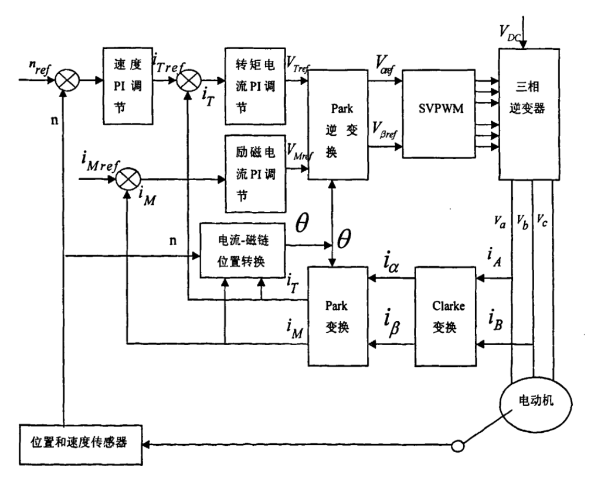
Figure 1: Block diagram of brushless motor field-oriented control.
In the FOC algorithm, essentially, we
1.2 Park Transform and Inverse Park Transform.
The Park transform, also known as the dq coordinate transform in field-oriented control, is a
matrix . It can be used to transform the dimensions of three-phase motor parameters (such as phase voltage, phase current, and field-oriented information) in the stationary coordinate system to the rotating dq coordinate system. The purpose of the Park transform is mainly to achieve two key aspects of control: ① The projections iα, iβ of the three-phase AC currents ia, ib, ic on the two-dimensional coordinate axes α and β are equivalently transformed to the dq coordinate system. This decouples the motor's current signal into the direct axis (d-axis) and the quadrature axis (q-axis), providing two parameters iq, id for position estimation. The d-axis direction coincides with the rotor flux direction, and the q-axis direction is perpendicular to the rotor flux direction, thus enabling field depth control, aligning the motor's magnetic field with the d-axis, and maximizing the output torque. ② The output torque of the motor can be controlled by controlling the current along the q-axis. Essentially, the Park transform decouples the amplitude and angle of a highly coupled, difficult-to-control nonlinear system through coordinate matrix transformation, converting a conventional nonlinear system into a linear system for control, thereby achieving excellent dynamic control performance.
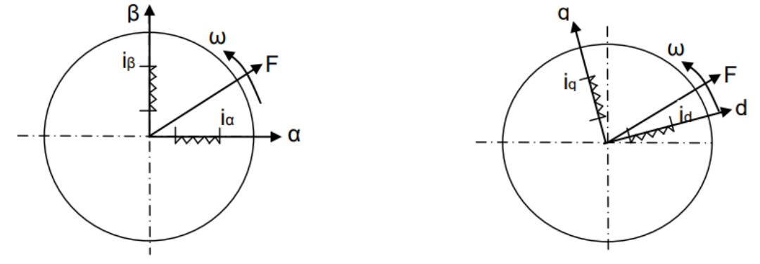
Figure 2: Conversion of a two-phase stationary coordinate system to a two-phase rotating coordinate system.
The essence of the Park transform is to transform the stationary αβ-axis coordinate system into a rotating dq-axis coordinate system through mathematical formulas. The dq-axis coordinate system always rotates with the rotor, meaning the goal is to control an AC motor using a linear system similar to that used for controlling a DC motor, thus obtaining two DC-dimensional components. θ represents the rotation angle of the rotating coordinate system relative to the stationary coordinate system. This rotation angle θ can be obtained in practical engineering operations through magnetic encoders or Hall sensors to acquire the real-time operating rotation angle of the motor. The rotation of the coordinate system in the corresponding mathematical formula involves the use of a rotation matrix. The matrix representation of the Park transform is obtained by multiplying the stationary coordinate system and the rotation matrix in a multiplier:
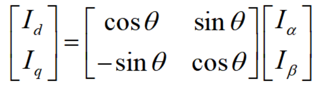
Figure 3: Park Transform Matrix Representation
. The inverse Park transform is the reverse operation of the Park transform, converting the voltage or current signal in the dq-axis rotating coordinate system into a signal in the αβ stationary coordinate system. This allows the output signals Vα and Vβ to be used as input signals for SVPWM to control the three-phase inverter circuit, thereby controlling the actual three-phase AC motor system. In other words, it converts the DC signals Vq and Vd of the front-end PI controller into sinusoidal signals, i.e., converting DC dimensional signals into AC dimensional signals. The corresponding matrix representation is shown in
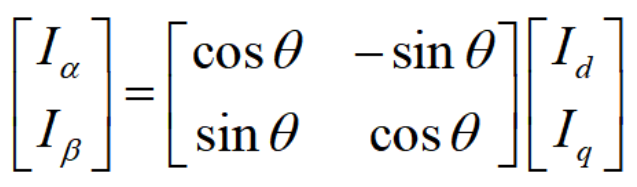
Figure 4: Inverse Park Transform Matrix Representation.
Using Matlab's Simulink simulation function, the built-in application analyzes the signals, preprocesses the time domain, frequency domain, and linear system analysis to model and simulate the Park transform and inverse Park transform. The Park sub-encapsulation module establishes three inputs Iα, Iβ, and θ, and two outputs Id and Iq. The following figure shows the Simulink simulation model of the Park transform built in Matlab.

Figure 2: Block diagram of Park transform based on Simulink
. In the encapsulated submodule, matrix input functions are added to the Park transform module to solve for the mathematical formulas Id and Iq. For the parameters Iα and Iβ, the output of the Clark transform can be used as the input to the Park transform. When testing the Park transform module separately, a sinusoidal current can be injected by a signal generator as the input parameter. Simultaneously, an analog oscilloscope is connected to the back of the module to observe the waveform generated by the Park transform, as shown below.
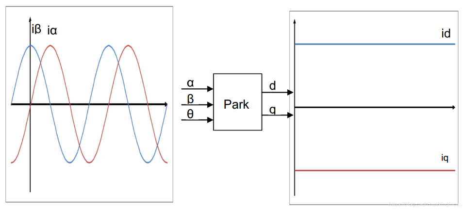
Figure 2: Output waveform of Park transform based on Simulink .
Similarly, three input parameters are added to the inverse Park module: Vd and Vq in the dq coordinate system, the angle value θ, and the two generated output parameters Vα and Vβ. These three signals are combined to facilitate module linking and import into the function module tool. The matrix transformation mathematical formula of the inverse Park transform is used to solve for Vα and Vβ. The following figure shows the Simulink simulation model of the inverse Park transform built in Matlab.
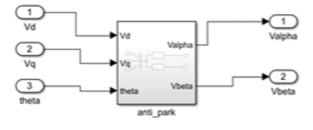
Figure 3: Sub-block diagram of the inverse Park transform module based on Matlab/Simulink.
In the inverse Park transform, since Vd and Vq are linear constant input DC signal parameters in the rotating coordinate system, the proposed angle information is generated by a signal with a period of 0.1 and an output phase range of 0-2π. Given that the current value Vd = 0 and Vq = 1, the signal flow is transformed into Vd and Vq. After the inverse Park transform and under the tuning of the angle information, the two DC information signals are superimposed on the angle information, converting into two sinusoidal AC waveforms with an amplitude of 1 and a phase difference of 90° along the α and β axes. The converted waveforms are shown in Figure

2: Output waveform of the inverse Park transform based on Simulink. Figure
1.3 Clark transformation and inverse Clark transformation:
Clark coordinate transformation is an important transformation in the FOC control flowchart. We need to understand why Clark coordinate transformation is necessary and how it differs from Park transformation. First, because magnetic field vector control requires the motor rotor to rotate continuously within one revolution, and the stator coils are 120° out of phase, it is necessary to rely on three-phase coils to simulate a continuously rotating magnetic field to drive the rotor to rotate. To generate a continuously rotating magnetic field, Faraday's law of electromagnetic induction must be applied, that is, the three-phase coils need to have sinusoidal alternating current to generate a continuously rotating magnetic field. In other words, the coils must be supplied with three-phase sinusoidal voltage to generate three-phase sinusoidal current to control the three-phase motor. The Clark transform decomposes the three-phase current and projects it onto the stationary ab coordinate axis to obtain ia, ib, and ic. It then transforms the input three-dimensional three-phase signal to obtain iα and iβ signals in a two-dimensional rectangular coordinate system (αβ coordinate system), which are then used as inputs to the Park transform. It can be understood that the collected three-phase currents ia, ib, and ic are three-phase AC currents. After the Clark transform, they are essentially sinusoidal AC signals on the α and β axes. At this point, the angle and amplitude information are not decoupled. However, true decoupling occurs when the current and angle information are used as the dq axis after the Park transform. This decoupling is then supplied to the PID controller for feedback control, forming a true closed loop. In summary, the essence of the Clark transform is to transform the spatial vector representation from a three-phase stationary coordinate system to a three-phase stationary coordinate system. The coordinate system is converted to a two-phase stationary coordinate system, as shown in

Figure 2. For the three -phase
currents Ia, Ib, and Ic of the brushless motor, the prerequisite for using them as input parameters for the Clark transformation is obtaining the motor's current parameters. This design uses a sensorless drive with three-resistance sampling, meaning that instead of using encoders or Hall sensors for three-phase current sampling, an observer is used to predict the motor parameter model. The corresponding values of Ia, Ib, and Ic are projected onto the abc axes of the coordinate system with a 120° phase error. Based on the direction projection calculation formula and the constraint of Kirchhoff's Law (KVL) Ia + Ib + Ic = 0, the mathematical expression for the rotation matrix using equal-amplitude transformation is shown in the figure below. The purpose of the 2/3 transformation coefficients for the Clark coordinate transformation is to obtain equal-amplitude variation coefficients based on the equal-amplitude variation of FOC.

Figure 4: Clark Transform Matrix Representation. The
Clark transform rotation matrix transformation formula is used in a function submodule using MATLAB/Simulink simulation tools. Three input quantities are Ia, Ib, and Ic, and two output quantities are Iα and Iβ. The simulation model is shown below:

Figure 4: Clark Transform Block Diagram Based on Matlab-Simulink.
The Simulink simulation block diagram shows that the three-phase currents Ia, Ib, and Ic, with a phase difference of 120°, acquired from the actual engineering design, are converted into two-phase sinusoidal AC currents Iα and Iβ by the encapsulated Clark transform submodule. The phase rotating coordinate system is transformed into a stationary two-phase coordinate system. The corresponding simulation result waveform is shown below:

Figure 2: Output waveform of Clark transform based on Simulink. The
inverse Clake transform is the inverse transformation of the Clark transform. The forward transform converts the three-phase current from the time domain to the αβ axis rotating coordinate system. In actual engineering, the α axis in the αβ coordinate system is aligned with the zero-sequence component of the current parameter by default, and the β axis is aligned with the positive and negative sequence components of the current parameter. Essentially, the two-phase sinusoidal current after the three-phase AC current is transformed is input into the Park transform, and the current and angle information of the dq axis are decoupled and separated, which makes it easier to input the parameter information into the PID for feedback. The inverse Clark transform plays the role of restoring the αβ components in the rotating coordinate system to the actual dimensions of the brushless motor in the time domain. It is worth noting that the Park transform and Clarke transform transform current, while the inverse Park transform and inverse Clarke transform transform voltage. The mathematical formula for their rotation matrix transformation is as follows:
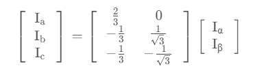
Figure 4: Matrix representation of the inverse Clark transform. The
inverse Park transform is encapsulated in the Fcn function module of Matlab/Sumilink. The matrix representation of the inverse Clark transform is input to the Fcn module as the transformation function expression. The Iα and Iβ after the Clark transform are used as input quantities to obtain the three-phase AC current signals Ia, Ib, and Ic. The corresponding block diagram is as follows:
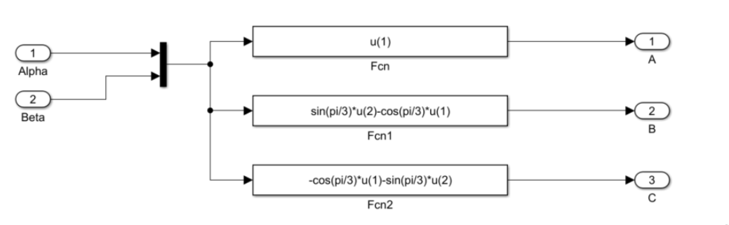
Figure 4: Block diagram of the inverse Clark transform based on Matlab-Simulink.
1.4 SVPWM modulation principle driving
SVPWM (Space Vector Pulse Width Space vector pulse width modulation (SVM) is a precise voltage output control based on vector control theory. A space vector is defined as a virtual vector generated during the control of a brushless motor. Compared to PWM (Pulse Width Modulation), which converts the input signal into a square wave pulse signal, a space vector is characterized by its ability to determine both magnitude and direction in space. In brushless motor drive methods, there are generally two types: trapezoidal wave six-step commutation drive and sinusoidal wave drive. In the operating principle of a synchronous motor, a sinusoidal alternating current with a 120° phase difference is typically applied to the three-phase stator windings ABC. This generates a composite rotating magnetic field, which drives the permanent magnet rotor's own magnetic field. The motor essentially rotates with this composite rotating magnetic field. The composite vector within the sector region is precisely the waveform obtained by controlling the output of the three-phase full-bridge inverter. The three-phase inverter is essentially a drive circuit composed of six upper and lower bridge arm MOSFETs, capable of converting DC parameters into AC parameters, i.e., generating a circuit where the current flow direction can be changed. Different voltages (currents) in different directions are applied at different times to drive the brushless motor. The three-phase inverter circuit is shown below:

Figure 4: BLDC three-phase full-bridge inverter circuit.
Its principle is to drive the motor by the conduction relationship of two pairs of MOSFETs. In order to prevent the upper and lower switches from forming a short circuit, the upper and lower switches of the same bridge arm must be complementary. Then, the full bridge composed of three half-bridges is recorded according to the conduction status. The total number of combinations of upper and lower bridge arm conduction is 000, 001, 010, 011, 100, 101, 110, 111. These 8 switch combinations correspond to six non-zero vectors in space, namely U1 (001), U2 (010), U3 (011), U4 (100), U5 (101), U6 (110) and two non-zero vectors U0 (000) and U7 (111). The zero space vector represents that the six MOSFET combinations cannot form an upper and lower conduction.
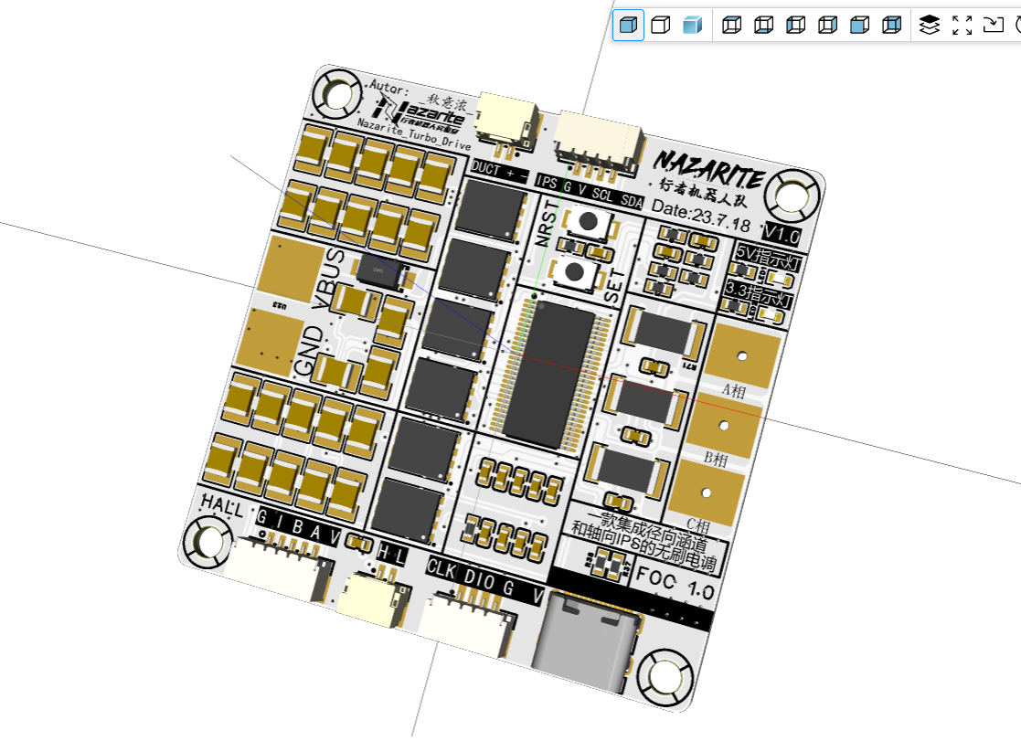
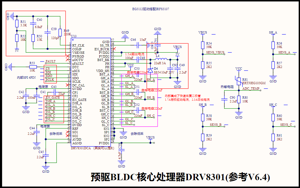
Project Hardware Circuit Introduction:

This project serves as an early attempt at an integrated brushless motor drive and control design. Some details may not be perfect, so please be gentle with your criticism. Below is a brief introduction to the design principles: Firstly, in terms of the overall hardware circuit: The integrated brushless motor control driver consists of a controller and a driver. The system hardware design includes a main control center unit module, a filter capacitor module, an LED indicator module, a crystal oscillator RCC circuit, a SW download circuit module, a reset circuit module, a Vcp driver Type-C analog serial port module, a CAN communication interface module, a DC-DC step-down module, a starting current-energy storage capacitor bank module, a high-side current sampling and detection module, an encoder interface, a three-phase full-bridge inverter circuit module, a pre-drive core control processor module, a radial IPS interface, an axial duct interface, a three-phase output interface, and a power input interface. Secondly, regarding the schematic design, the schematic is a culmination of information compiled from the following relevant materials. For those unfamiliar with FOC (Fan-Driver) technology, only introductory notes are provided (currently being updated), without answering specific FOC questions. For the most popular FOC driver boards both domestically and internationally, Benjamin and Odrive are widely recognized. As a hardware enthusiast, collecting numerous brushless motor driver boards is my responsibility and obligation (lol). Below are all the relevant materials I've studied. If you're interested, feel free to ask me questions in the comments. This open-source release only covers the hardware design; the software design is currently being packaged and organized. For

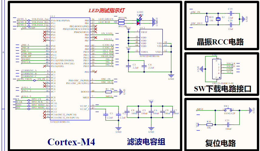
the minimum system circuit module, the main control unit chip selected in this paper is the STM32F405RGT6, used to provide drive control signals. This main control chip is a high-performance 32-bit ARM Cortex-M4 core microcontroller from STMicroelectronics, with a maximum clock frequency of 168MHz. It also integrates a hardware floating-point unit (FPU), has 1MB of FLASH and 192KB of SRAM, and can meet the requirements for storing complex FOC algorithm programs. Its rich peripherals, such as SPI, I2C, USART, and CAN communication interfaces, along with its 12-bit 16-channel ADC and 12 general-purpose 16-bit system timers, can meet the needs of integrated brushless motor control drivers. In the Robocon National Robotics Competition, where both hardware cost and processing performance are crucial, this model meets the requirements of lower cost and superior control.
The main control center utilizes three complementary PWM signal outputs: INH_A, INH_B, and INH_C from PA8-PA10, and complementary signals INL_A, INL_B, and INL_C from PB13-PB15. Internally, the complementary PWM signals are all output by timers. It employs one I2C communication channel (I2C2_SCLA and I2C2_SDA from PB10-PB11) for bidirectional communication with the radial IPS display module, and one CAN communication channel (CAN1_RX and CAN1_TX from PB8-PB9) for bidirectional communication with external brushless motors. Three channels (PC6-PC8, HALL1, HALL2, HALL3) are used for connecting to the Hall effect encoder. One SPI interface (PC9-PC12) is used by the main control unit to select the amplification factor of the internal current sampling operational amplifier when communicating with the pre-driver chip DRV8301DCAR. Three voltage monitoring channels (PA-PA2, corresponding to Voltage_A, Voltage_B, Voltage_C) are used for system voltage monitoring. Three current sampling monitoring channels (PC0-PC2, corresponding to Current_A, Current_B, Current_C) are used for system current sampling, providing reference parameters for the underlying current loop. Pre-programmed USB-USART bidirectional communication firmware (USB_DP and USB_DM) is provided, allowing connection via a Type-C cable to a graphical debugging tool (VOFA+) as a host computer, or control via the Benjamin VESC open-source VESC_Tool host computer. Through analog oscilloscope functionality and parameter display, various waveforms and motor speed, current, and other information can be displayed in real time during debugging. The minimum system circuit of the main control unit includes a two-pin passive crystal oscillator, which improves the oscillation stability of the external RCC clock. The download circuit uses a 4-pin LINK download method, with BOOT0 pulled low by default. Two LED test indicators are used to test whether the main control unit can be programmed normally.
Debugging the FOC algorithm for the brushless motor mainly focuses on whether the main frequency, timer, and current sampling module meet the requirements. The pre-driver chip DRV8301DCAR for the drive circuit requires three complementary PWM wave signals from the main control unit. The 12-bit ADC required by the current sampling high-side monitoring module has an accuracy of 1/4096, which meets the system monitoring requirements. The three-phase current generated by vector control will be acquired by the corresponding sampling module. The main control unit provides multiple programmable I/O ports for debugging. In summary, the STM32F405RGT6 chip fully meets the design requirements and can be used as the main control unit for an integrated brushless motor control driver. The following figure shows the control circuit of the main control unit.

The entire system's power management (PMU) is powered by a single 5500mAh TB47 DC power supply with a 6S lithium battery. The pre-driver chip DRV8301DCAR has a PVDD input voltage range of 6V-60V, powered by a DC power supply. The DRV8301 datasheet clearly states that it has an internal constant current source DC-DC chip with a built-in BST_BK pin. Only an external capacitor, inductor, and Schottky diode are needed to form a 5V step-down circuit. The 24V DC input voltage is automatically stepped down to 5V by the chip, and this 5V power supply will provide power to the encoder's external input interface. Therefore, this system's power module can reduce the need for a separate 24V-to-5V step-down power supply circuit. The main control unit, STM32F405RGT6, requires a 3.3V power supply; therefore, only one external step-down circuit is needed to power the main control unit. The main DC-DC step-down circuit is shown in the diagram below. The 24V input voltage can be provided with a 3.3V 3A output load capacity through the SY8089A1AAC. For the low-dropout step-down selection, this system uses a low-ripple DC-DC circuit instead of the commonly used LDO circuit. The selected DC-DC chip is the SY8089 from the RM-C development board, a driver chip from Silergy. The SY8089 and SY8089A are high-efficiency, high-frequency synchronous step-down DC-DC regulator ICs capable of providing up to 2A of output current. The SY8089 and SY8089A operate over a wide input voltage range from 2.7V to 5.5V and integrate the main switch and synchronous switch with extremely low RDS(ON) to minimize conduction losses. Low output voltage ripple and small external inductor and capacitor size enable switching frequencies greater than 1MHz. The SY8089 integrates short-circuit and overvoltage latch-up protection. Features include low RDS(ON) of the internal switches (top/bottom): 110mΩ/80mΩ. 2.7-5.5V input voltage range, 2A continuous, 3A peak load current capability, 1MHz switching frequency minimizes external components, internal soft-start limits inrush current, reliable short-circuit protection: SY8089: latch-up shutdown protection, SY8089A: hooded cup mode protection, reliable overvoltage protection: SY8089: latch-up shutdown protection, SY8089A: non-latching shutdown protection. Actually, this is all just background information. For hardware enthusiasts, mastering the selection of relevant inductors, fast recovery diodes, and feedback loops is sufficient.
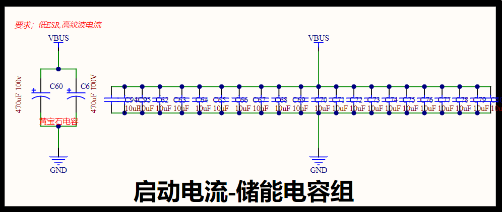
The startup current-energy storage capacitor bank is used for buffering the power-on of the 6S high-voltage circuit, especially for the pre-driver chips required by the FOC driver board, such as FD6288, EG2134, IR2101, etc. For VIN power-on PVDD, low ESR and high ripple current are required. Here, we chose a yellow sapphire capacitor as the filter capacitor, paired with a 10uF small capacitor bank, forming a large capacitor + small power supply combination. Many interviewers like to ask, "Why not just use a single 22uF capacitor instead of two 10uF and two 100nF capacitors in parallel on the power supply? This would save PCB space." This is a relatively niche question, and the chances of it appearing in an interview are slim, but it's frequently used in practice. Generally, engineers with a few years of experience either understand this very well or overlook such small details. This discussion focuses on the insertion loss of the filter. In the 2MHz~300MHz target frequency band, the combination of 2x10uF + 2x0.1uF capacitors has a higher insertion loss than a single 22uF capacitor, making it more beneficial for power supply filtering. However, filter insertion loss is only one dimension of this analysis; other interpretations exist, such as the capacitor's frequency impedance curve. Simulation comparison and verification: Some might mention the capacitor's frequency impedance curve, but we won't discuss that today. We'll analyze this from the perspective of the filter's S-parameters. We'll use Murata's online simulation software SimSurfing for verification. We assume the 12V power supply is generated by a Buck circuit with a switching frequency of 2.2MHz. To more clearly observe the comparison effect, we focus on the frequency range of 2MHz-300MHz for this power supply. Step 1: Build a simple filter circuit: 0.1uF + 10uF.
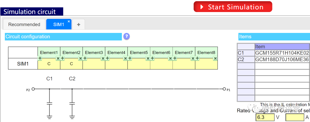
Observe the S21 (insertion loss) curve of this filter circuit, as shown in the figure below.
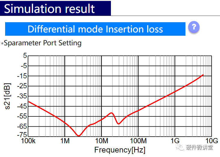
It might not be immediately apparent. What would happen if we combined the two 10uF and two 0.1uF units from the power supply into a single 22uF unit?
Step 2: Build another filter circuit with only 22uF:
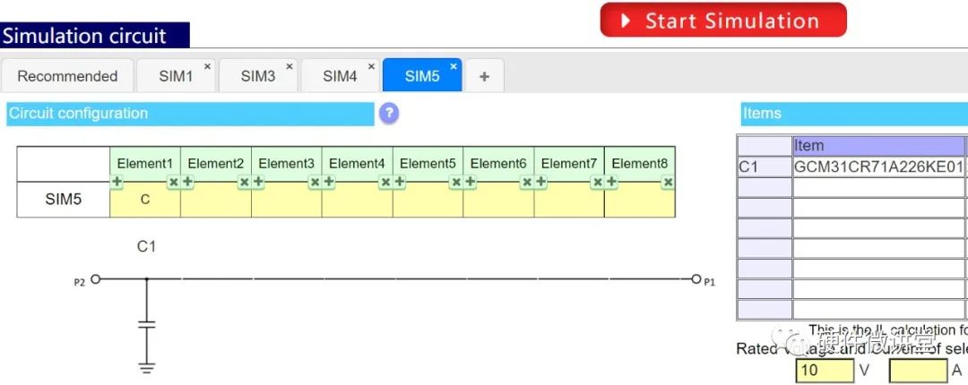
Observe the S21 curve of the filter circuit again.
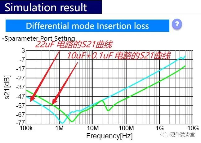
It is clear that the S21 curve of 10uF + 0.1uF has a greater insertion loss in the 2MHz~300MHz range. According to the impedance mismatch principle of filters, the higher the insertion loss of the filter circuit in the target frequency band, the better.
That is, 10uF + 0.1uF has a better filtering effect within a limited frequency band.
Step 3: Build another filter circuit: 2x0.1uF + 2x10uF.
Let's look at the S21 curve of the filter circuit. As shown in the figure below: Among the three schemes, in the 2M~300MHz range, 2x10uF + 2x0.1uF has the highest insertion loss, meaning the best filtering effect.

It's also important to note that topaz capacitors are not easy to purchase. Large-capacity topaz capacitors are extremely difficult to find on LCSC's online store. The most significant characteristic of topaz capacitors is their very low ESR. Compared to the commonly used aluminum electrolytic capacitors, topaz capacitors have high ripple current, playing a significant role in power supply stability. After processing the power-on waveform using the oscilloscope's trigger function, we tested the filtering and ripple effects of solid-state electrolytic capacitors and topaz capacitors during our engineering practice. The oscilloscope results show that the topaz capacitor's effect is significantly higher.

Meanwhile, regarding the current loop, one of the most important underlying three loops in FOC (Focus on Current Control), our primary focus is on the design of the current sampling circuit. Currently, the most widely used FOC circuit is the three-resistor sampling circuit, but two-resistor sampling circuits are also available. In fact, I believe a two-resistor sampling circuit is sufficient. For the two-segment sampling of phase current, the last segment can be solved using Kirchhoff's law and the KVL equation: Ia + Ib + Ic = 0. However, the most discussed aspects of sampling circuits are high-side and low-side sampling circuits. You can refer to the following article for further understanding: Current detection application
circuits are commonly used in scenarios such as high-voltage short-circuit protection, motor control, DC/DC converters, system power management, secondary battery current management, and battery management.

For most applications, current is measured by sensing the voltage drop across the resistor.

Generally, resistors with voltage drops of tens to hundreds of mV when current flows through them are used for current sensing. Low-resistance resistors for current sensing use smaller resistance values of several Ω or less. Sensing large currents of tens of A requires extremely small resistance values of several mΩ. Therefore, metal plate and metal foil type low-resistance resistors, which excel in small resistance values, are commonly used . Small currents are detected using larger resistance values of hundreds of mΩ to several Ω.
When measuring current, the resistor is usually placed in two positions in the circuit. The first position is between the power supply and the load. This measurement method is called high-side sensing. The second position is usually between the load and ground. This current sensing method is called low-side current sensing.

Both methods have advantages and disadvantages. Low-side resistors add unwanted additional impedance in the grounding path; circuits using high-side resistors must withstand relatively large common-mode signals. One advantage of low-side current measurement is the common-mode voltage, i.e., the average voltage at the measurement input is close to zero. This makes it easier to design application circuits and select suitable devices for this measurement. The low-side current sensing circuit measures a voltage close to ground. This method is preferred for measuring current when dealing with very high voltages or in applications where the power supply voltage may be prone to spikes or surges. Low-side current sensing is resistant to high-voltage spikes and can monitor current in high-voltage systems.
The current sensing circuit
performs low-side detection.
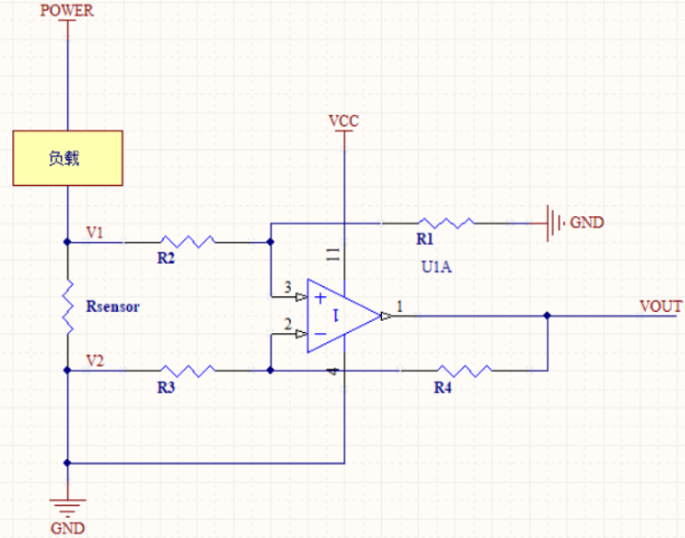
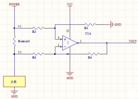
The main drawback of low-side current sensing is that the voltage drop across the sensing resistor differs depending on whether the power supply ground or the load/system ground is used. This can cause problems if other circuits reference the power supply ground. To minimize this issue, all interconnected circuits should reference the same ground. Reducing the current sensing resistor value helps minimize ground drift.
As shown in the diagram above, if the op-amp's GND pin is referenced to the positive terminal of RSENSE, its common-mode input range must cover below zero, i.e., GND - (RSENSE × ILOAD). Rsensor isolates ground (GND).
High-side sensing
has become very convenient to use differential amplifiers in high-side current measurement with the availability of numerous ICs containing high-precision amplifiers and precision matching resistors. High-side sensing has driven the development of current sensing ICs, reducing the problems of parameter variations and excessive component count associated with discrete components. Integrated circuits have made our use more convenient. The diagram below shows a high-side sensing IC solution:

the detection circuit outputs
a pattern from both ends of the resistor to detect the voltage drop as current flows through it. The voltage detection connection is shown in Figure (2) below. It is recommended to lead it out from the inner center of the resistor electrode pad. This is because the copper foil pattern of the circuit board also has a small resistance value, and it is necessary to avoid the influence of the voltage drop caused by the resistance value of the copper foil pattern. If the voltage detection pattern is led out from the side of the electrode pad as shown in Figure (1), the detection object will be the voltage drop of the low resistor resistance value plus the copper foil pattern resistance value, and the current cannot be detected correctly.

PCB Layout Reference:

According to the conclusions drawn from VESC4.0 and VESC6.15 PLUS versions, the previous versions of VESC all used low-cost low-end sampling circuits, and all used in-phase differential operational amplifier circuits. We are more familiar with the sampling circuits built by conventional operational amplifiers such as INA226, LM321, and LM254. Low-end sampling has a lower cost and is more friendly to self-developed testing. High-end sampling commonly uses the AD8418 from ADI, but the cost of high-end sampling is higher, and the obtained sampling value is more accurate. The advantages and disadvantages of the two different sampling methods are compared above.
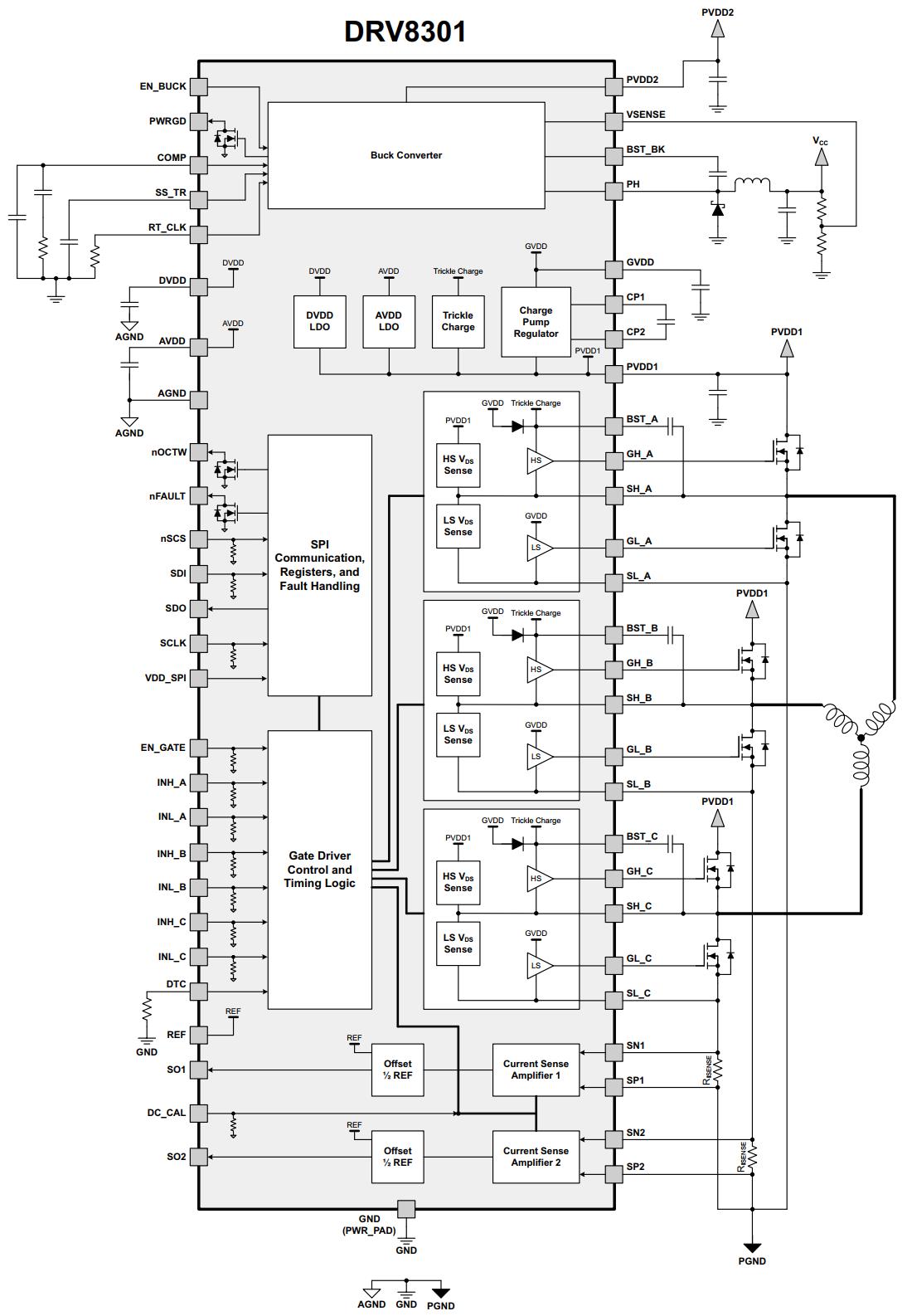
Regarding the selection of pre-driver chips, different pre-driver chips include built-in MOS, external MOS, and also built-in driver and external driver ICs. The DRV series all use external MOS and built-in driver ICs. The limitation of the internal driver is that the GVDD waveform amplitude of the bootstrap capacitor is limited to the inside of the chip. At the same time, the Schottky diode is also integrated inside the chip. The detailed description of this DRV8301 is as follows: Voltage 6V to 60V,
1.7A gate drive current, 2.3A sink current ,
supports 3.3V and 5V interfaces
, integrates a buck power supply, adjustable output voltage and switching frequency, can provide 1.5A current
, adjustable dead time, adjustable overcurrent protection, PVDD and GVDD undervoltage lockout, GVDD overvoltage lockout, over-temperature warning/shutdown.
Internal block diagram and pin description:
name
NO.
Type
Description
EN_BUCK
55
I
buck power enable pin. Floating enable. Uses two resistors to adjust the input voltage lockout value.
PWRGD
4
O
open-drain output, requires external pull-up. This pin will output low if the buck output voltage is low due to thermal shutdown, dropout, overvoltage, or EN_BUCK shutdown.
COMP
2
O
Output and input-to-output switching current comparator of the buck error amplifier.
SS_TR
56
I
Buck soft-start and tracking. An external capacitor connected to this pin sets the output rise time. Because the voltage on this pin overrides the internal reference, it can be used for tracking and sequencing.
RT_CLK
1
I
Connect a resistor to ground to regulate the external clock of the buck power supply .
PVDD2
53, 54
P
Buck power supply input.
VSENSE
3
I
Buck power supply output voltage feedback pin.
BST_BK
52
P
Buck power supply bootstrap capacitor pin.
PH
50, 51
O
Connect to the high-side MOSFET inside the buck power supply; an external inductor and diode circuit is needed to complete the buck circuit.
Other power supply related pins:
Name,
NO.,
Type,
Description:
DVDD
23
P
Internal 3.3V supply voltage.
AVDD
27
P
Internal 6V supply voltage.
AGND
28
P
Analog ground.
GVDD
13
P
Internal gate drive voltage regulator.
CP1
14
P
Charge pump pin.
CP2
15
P
Charge pump pin.
PVDD1
29
P
Power supply for gate driver, sampling current amplifier, and SPI communication. PVDD1 is independent of the buck power supply PVDD2.
SPI communication and fault indication pins:
name,
NO.,
Type,
description:
nOCTW
5
O
Overcurrent/overtemperature alarm indication. Open-drain output, requires external pull-up resistor. Output mode can be configured via SPI register modification.
nFAULT
6
O
Fault indication. Open-drain output, requires external pull-up resistor.
nSCS
8
I
SPI Chip Select
SDI
9
I
MOSI
SDO
10
O
MISO
SCLK
11
I
SCK
VDD_SPI
49
I
SPI power supply, can use 3.3V or 5V
gate drive and PWM input pin
name
NO.
Type
Description
EN_GATE
16
I
Enable gate drive and sampling current amplifier.
INH_A
17
I
Half-bridge A high-side PWM input
INL_A
18
I
Half-bridge A low-side PWM input
INH_B
19
I
Half-bridge B high-side PWM input
INL_B
20
I
Half-bridge B low-side PWM input
INH_C
21
I
Half-bridge C high-side PWM input
INL_C
22
I
Half-bridge C low-side PWM input
DTC
7
I
Connect an external resistor to GND to adjust the dead time. 0 to 150K corresponds to a dead time of 50ns to 500ns.
Half-bridge circuit related pin
name
NO.
Type
Description
SL_C
34
I
Source of the low-side MOSFET of half-bridge C.
GL_C
35
O
Gate drive output of the low-side MOSFET of the half-bridge C.
SH_C
36
I
Source of the high-side MOSFET of the half-bridge C.
GH_C
37
O
Gate drive output of the high-side MOSFET of the half-bridge C.
BST_C
38
P
Bootstrap capacitor of the half- bridge C.
SL_B
39
I
Source of the low-side MOSFET of the half-bridge B.
GL_B
40
O
Gate drive output of the low-side MOSFET of the half-bridge B.
SH_B
41 Source of the high-side MOSFET of the half-bridge B.
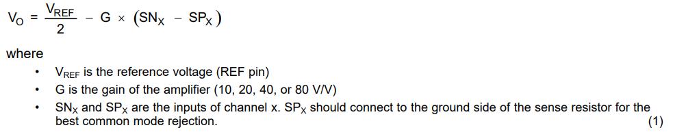
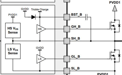
GH_B 42 O Gate drive output of the high-side MOSFET of the half-bridge B. BST_B 43 P Bootstrap capacitor of the half- bridge B. SL_A 44 Source of the low-side MOSFET of the half-bridge A. GL_A 45 O Gate drive output of the low-side MOSFET of the half-bridge A. SH_A 46 Source of the high-side MOSFET of the half-bridge A. GH_A 47 O Gate drive output of the high-side MOSFET of the half-bridge A. BST_A 48 P half-bridge A bootstrap capacitor. SN1 33 I Connected to the upper side of current sampling resistor 1. SP1 32 I Connected to the lower side of current sampling resistor 1. SN2 31 I Connected to the upper side of current sampling resistor 2. SP2 30 I Connected to the lower side of current sampling resistor 2. SO1 25 O Output of current amplifier 1. SO2 26 O Output of current amplifier 2. REF 24 I Sets the bias voltage of the sampling current amplifier, which is equal to half the voltage on this pin. Connected to the ADC reference voltage of the MCU. DC_CAL 12 I When DC_CAL is pulled high, the device short-circuits the input of the sampling current amplifier and disconnects the load. DC bias correction can be implemented by an external microcontroller. Sampling current amplifier
The DRV8301 includes two high-performance current amplifiers for accurate current measurement. The current amplifiers have four programmable gain settings via the SPI register: 10, 20, 40, and 80 V/V. The current amplifiers provide an output bias up to 3V to support bidirectional current sensing. The offset is set to half the voltage on the reference pin (REF). To reduce DC bias and drift over-temperature, a calibration method is provided via the DC_CAL pin or the SPI register. When DC calibration is enabled, the device short-circuits the current amplifier inputs and disconnects the load. DC calibration can be performed at any time, even during MOSFET switching, as the load is off. For best results, DC calibration is performed during the switch-off period with no load to reduce the impact of potential noise on the amplifier. The output of the current shunt amplifier can be calculated as follows: Overcurrent Protection (OCP)
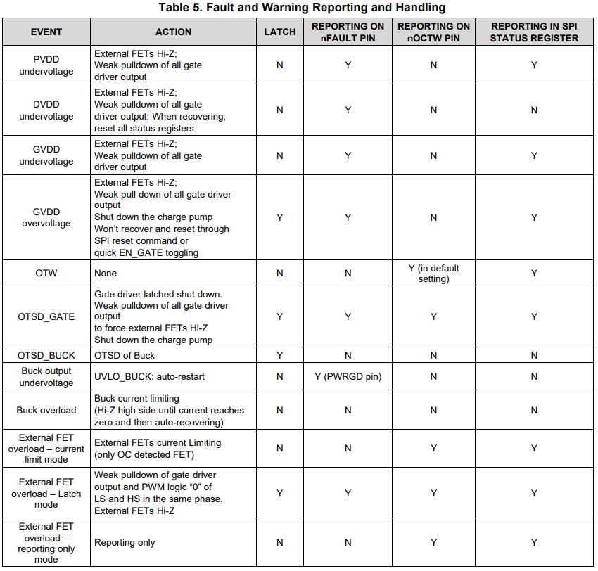
Function : Due to the internal resistance of the MOSFET, the current value can be converted to a voltage value using VDS = IDS × RDS(on), and then compared with the overcurrent value set via the SPI modification register to determine whether overcurrent protection is triggered. High-side overcurrent protection measures the voltage between PVDD1 and SH_X, while low-side protection measures the voltage between SH_X and SL_X. Therefore, it's best to use differential routing to eliminate PCB line resistance differences. The overcurrent value should ideally have a 20% margin. Four different overcurrent modes (OC_MODE) can be set via the SPI register. The OC status bit operates in latch mode. When an overcurrent condition occurs, the corresponding OC status bit is latched in the DRV8301 register until the next SPI read command. After the read command, the OC status bit is cleared from the register until another overcurrent condition occurs. 1. Current Limiting Mode: In current limiting mode, the device uses current limiting instead of shutting down during an overcurrent event. In this mode, the device reports the overcurrent event via the nOCTW pin. The nOCTW pin will be held low for a maximum of 64µs (internal timer) or until the next PWM cycle. If another overcurrent event is triggered by another MOSFET, the reporting will continue for another 64µs (internal timer will restart) or until two PWM signal cycles during the previous overcurrent event. In the field-effect transistor that detects overcurrent, the relevant status bit will be set. There are two current control settings in current-limiting mode. These are set by a single bit in the SPI register, with the default mode being CBC (cycle by cycle). Cycle by Cycle mode (CBC): In CBC mode, the MOSFET that detects overcurrent will be turned off until the next PWM cycle. Off-Time control mode: In Off-Time mode, when the MOSFET detects overcurrent, the off time is 64µs (set by an internal timer). If overcurrent is detected in another MOSFET, the timer will reset for another 64µs cycle, during which both MOSFETs will be disabled. During this period, normal operation of the specific MOSFET can be resumed with the corresponding PWM cycle. 2. Latch-off mode When an overcurrent event occurs, the high-side and low-side MOSFETs will be disabled in the corresponding half-bridge. The nFAULT pin and the nFAULT status bit will be activated along with the relevant status bit of the MOSFET that detected overcurrent. The OC status bit will be locked until the next SPI read command. The nFAULT pin and nFAULT status bit will be locked until a reset is received via the GATE_RESET bit or a fast EN_GATE reset pulse. 3. Report-only mode: In this mode, no protection action is taken when an overcurrent event occurs. Overcurrent events will be reported via the nOCTW pin (64 μs pulse) and the SPI status register. The external microcontroller should take appropriate action according to its own control algorithm. 4. OC disabled mode: The device will ignore and not report any overcurrent detections. Undervoltage protection (PVDD_UV and GVDD_UV) : When PVDD or GVDD falls below its undervoltage threshold (PVDD_UV/GVDD_UV), the DRV8301 provides undervoltage protection by pulling GH_X and GL_X low. This will put the external MOSFET in a high-impedance state. When the device is in PVDD_UV, it will not respond to SPI commands, and the SPI register will revert to its default settings. A transient undervoltage limit of PVDD1 from 13µs to 15µs will cause the DRV8301 to become unresponsive to external inputs until a full-power cycle. The transient condition is that PVDD1 is greater than the PVDD_UV level, and then PVDD1 drops below the PVDD_UV level within a specific time period of 13~15µs. Transient times shorter or longer than 13~15µs do not affect the normal operation of undervoltage protection. An additional large capacitor can be added to PVDD1 to reduce undervoltage transients. Overvoltage protection (GVDD_OV) : If the GVDD voltage exceeds the GVDD_OV threshold, the device will shut down the gate driver and charge pump to prevent potential problems associated with the GVDD pin or charge pump (e.g., short circuit of external GVDD capacitor or charge pump capacitor). The fault is a latched fault and can only be reset via the reset transition on the EN_GATE pin. Over-temperature protection implements a two-stage over-temperature detection circuit: • Stage 1: Over-temperature alarm (OTW) For the default setting, OTW is reported via the nOCTW pin (overcurrent and/or over-temperature warning). The OCTW pin can be configured to report OTW or OCW only via the SPI register. See the SPI register section. • Stage 2: Over-temperature latch-up shutdown for gate drivers and charge pumps (OTSD_GATE) OTSD_GATE is reported via the nFAULT pin. This is a latch-up shutdown, so the gate driver will not automatically resume operation even if the over-temperature condition no longer exists. EN_GATE reset or SPI (RESET_GATE) is required to resume normal operation of the gate driver after the temperature drops below the preset value tOTSD_CLR. SPI operation remains available, and during OTSD operation, register settings are retained in the device as long as PVDD1 is within the defined operating range. Fault and protection handling The nFAULT pin indicates when a shutdown event occurs, including overcurrent, over-temperature, over-voltage, or under-voltage events. Note that nFAULT is an open-drain signal. During power-on, nFAULT will be pulled high when the gate drive is ready for PWM input. The nOCTW pin indicates when an overcurrent or overtemperature event occurs. These events are independent of power-off. Table 5 provides a summary of all protection features and their reporting structures. Power-on/Power-off Sequence During power-up, all gate drive outputs remain low. Normal operation of the gate driver and current amplifier can be initiated by switching EN_GATE from low to high. The DRV8301 is ready to accept PWM input if no error exists. The gate drive always controls the MOS as long as PVDD is within its functional region, even in gate drive disabled mode. There is an internal diode from SDO to VDD_SPI, so VDD_SPI needs to be powered at the same power level as other SPI devices (if there is an SDO signal from another device). The VDD_SPI power supply should be powered on before any signal appears on the SDO pin and then powered off after all communication on the SDO pins is complete. EN_GATE Function Description
EN_GATE low is used to put the gate driver, charge pump, current amplifier, and internal regulator modules into a low-power mode to conserve energy. SPI communication is not supported in this state, and the SPI registers will revert to their default settings after a complete EN_GATE reset. The device will set the MOSFET output stage to high impedance mode as long as PVDD is present. When the EN_GATE pin goes high, it goes through a power-up sequence, enabling the gate driver, current amplifier, charge pump, internal regulator, etc., and resetting all latch faults associated with the gate driver block. EN_GATE will also reset the status register in the SPI table. When EN_GATE is toggled after an error event, all latch faults can be reset unless the fault still exists. When EN_GATE goes low, it immediately shuts down the gate driver block, so the gate output can put the external FET in high impedance mode. It then waits 10µs before completely shutting down the remaining blocks. A fast fault reset mode can be achieved by toggling the EN_GATE pin for a very short time (less than 10µs). This will prevent the device from shutting down other functional blocks, such as the charge pump and internal regulator, and allows for faster and simpler fault recovery. SPI will still function in such a fast EN_GATE reset mode. To perform a full reset, EN_GATE should be toggled for more than 20µs. This allows all functional modules to be fully shut down and reach a known state. A 10-20µs EN_GATE reset pulse (high→low→high) should not be applied to the EN_GATE pin. The DRV8301 has a transition region from fast reset mode to full reset mode, which can cause the device to become unresponsive to external inputs until a full power cycle. If a reset pulse of this cycle is expected on the EN_GATE pin, an RC filter can be added externally to the pin. Another way to reset all errors is to use the SPI command (RESET_GATE), which only resets the gate driver modules and all SPI status registers without shutting down other functional blocks. One exception is resetting the GVDD_OV error. A fast EN_GATE fast fault reset or an SPI command reset will not work for GVDD_OV faults. Resetting a GVDD_OV fault requires a complete EN_GATE session with a low-level hold time greater than 20µs. TI strongly recommends checking the system and boards when a GVDD_OV fault occurs.
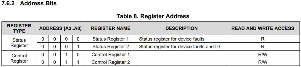
The SPI communication
data frame structure
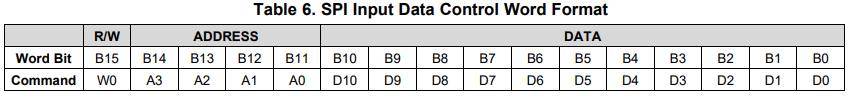
register
has four registers: two read-only status registers, two read-write control registers, and
the last circuit module is the familiar three-phase full-bridge inverter circuit. The essence of the three-phase full-bridge inverter circuit is to convert DC power into AC power through MOSFETs to control our brushless motor (BLDC or PMSM). Therefore, the most important aspect of the three-phase full-bridge inverter circuit is the selection of MOSFETs. Regarding MOSFET selection, I have compiled a relevant parameter table. It is especially important not to assume that MOSFET parameter selection only requires considering Vdss and Idss, because these two parameters are actually derived from the stable switching state of the MOSFET. (This brings us to our testing situation. In our first test of whether the waveform output from the DRV8301 under complementary PWM met the requirements, we only enabled the upper and lower MOSFETs of group A through CubeMX. The complementary PWM output from the MCU's timer was output to the MOSFETs via the DRV8301. Our test points showed that the waveform of the upper MOSFET was abnormal, and our dead time, according to the DCT pin configuration, did not function.) Furthermore, the DeadTime function we wrote in our software didn't work, but our MOSFETs didn't short-circuit due to lack of conduction time. Besides the abnormal waveform, the amplitude and phase were normal. However, we don't know why, suddenly the lower MOSFE


 京公网安备 11010802033920号

 MA60101FAN


