For details, please see CSDN: http://t.csdnimg.cn/0TDkd
and Zhihu: "Programmable Variable Gain Amplifier (Basic Version)" - Layout's article - Zhihu https://zhuanlan.zhihu.com/p/679622619
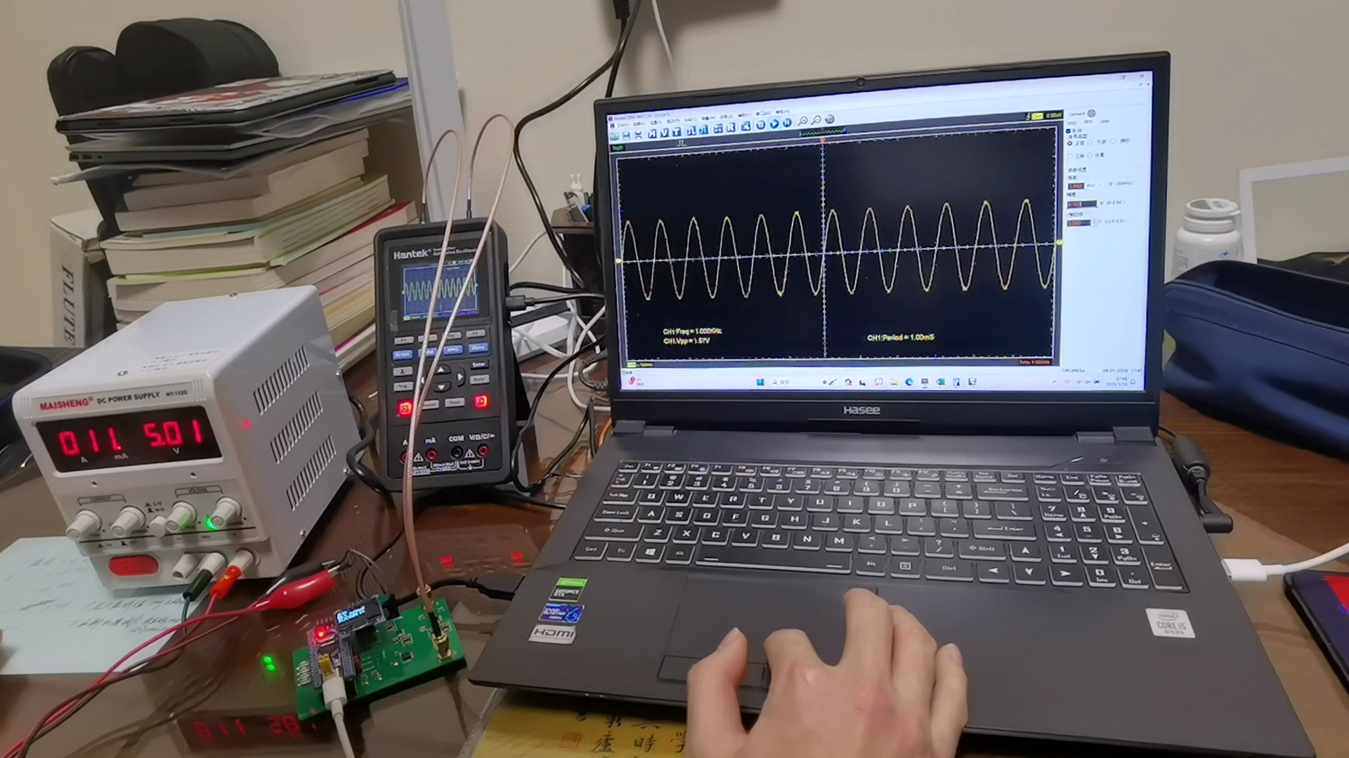
. LCSC's text editor is too difficult to use. Here are some actual test images, or you can watch the video directly.
Manual Mode_1.mp4
Automatic mode.mp4
ADC Data Compilation.xlsx
PDF_Variable Gain Amplifier (Basic Version).zip
Altium_Variable Gain Amplifier (Basic Version).zip
PADS_Variable Gain Amplifier (Basic Version).zip
BOM_Variable Gain Amplifier (Basic Version).xlsx
96253
DIY Mini Speaker
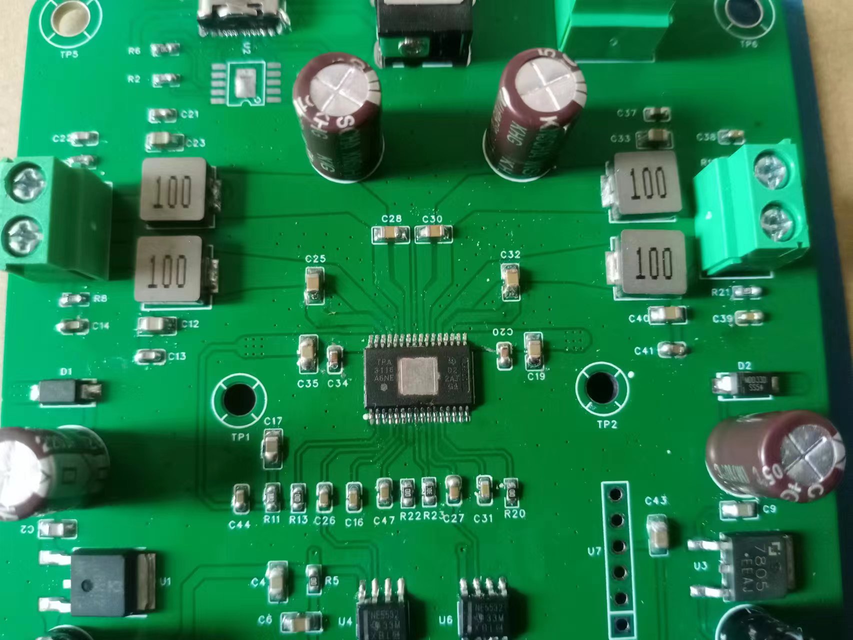
This is my first time building an amplifier, and I'm a complete audio novice. I'd appreciate any guidance from experienced users. I'm using the Texas Instruments TPA3116 Class D digital amplifier chip, and it has three input methods: wired AUX 3.5mm headphone and RCA inputs, and Bluetooth input. It supports 2.0 dual-channel stereo.
To build a low-cost speaker yourself,
we first need to know what materials are needed. For beginners like me, all we need is for the speaker to make a sound.
We need a sound-producing element, which is the speaker,
a power amplifier, and a cabinet.
Power amplifiers are available online, and we can also make one ourselves. This project focuses on building a power amplifier.
What are the circuit modules on this amplifier board?
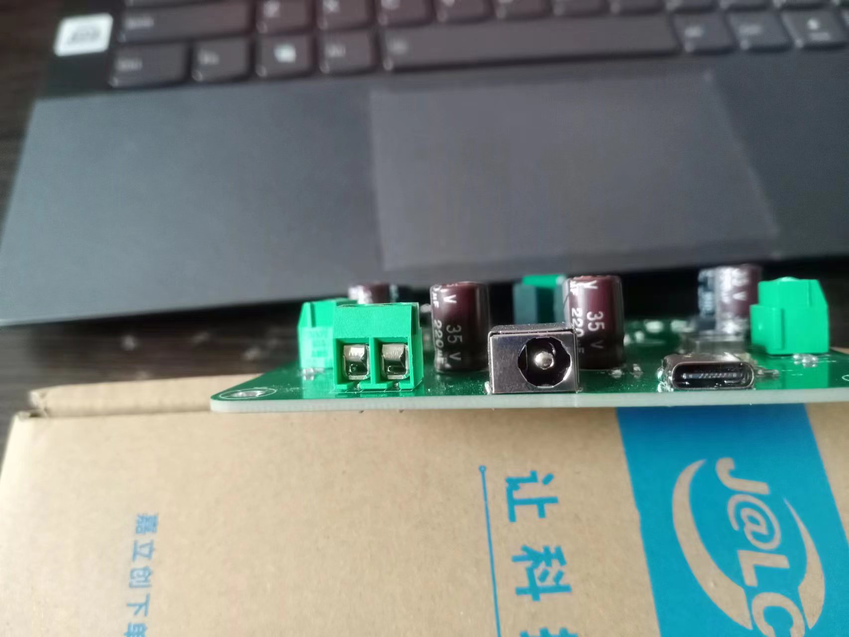
1. First, no matter what board you make, the first thing you need to do is the power module! This supports three power input methods: Type-C input, DC power socket with an inner diameter of 2.5mm, and screw-type terminal blocks/5mm 1x2P.
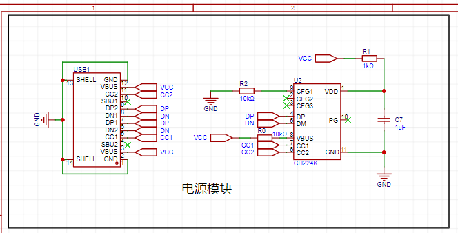
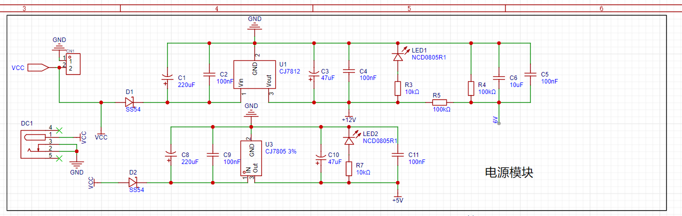
This supports 12V and 5V voltages.
The second is the preamplifier

input module
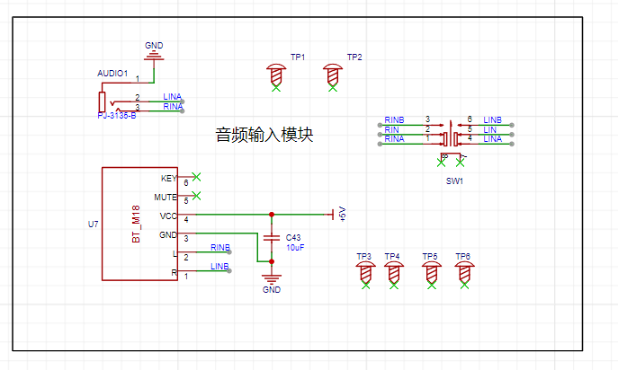
, the most important amplifier chip circuit module.

Physical demonstration and

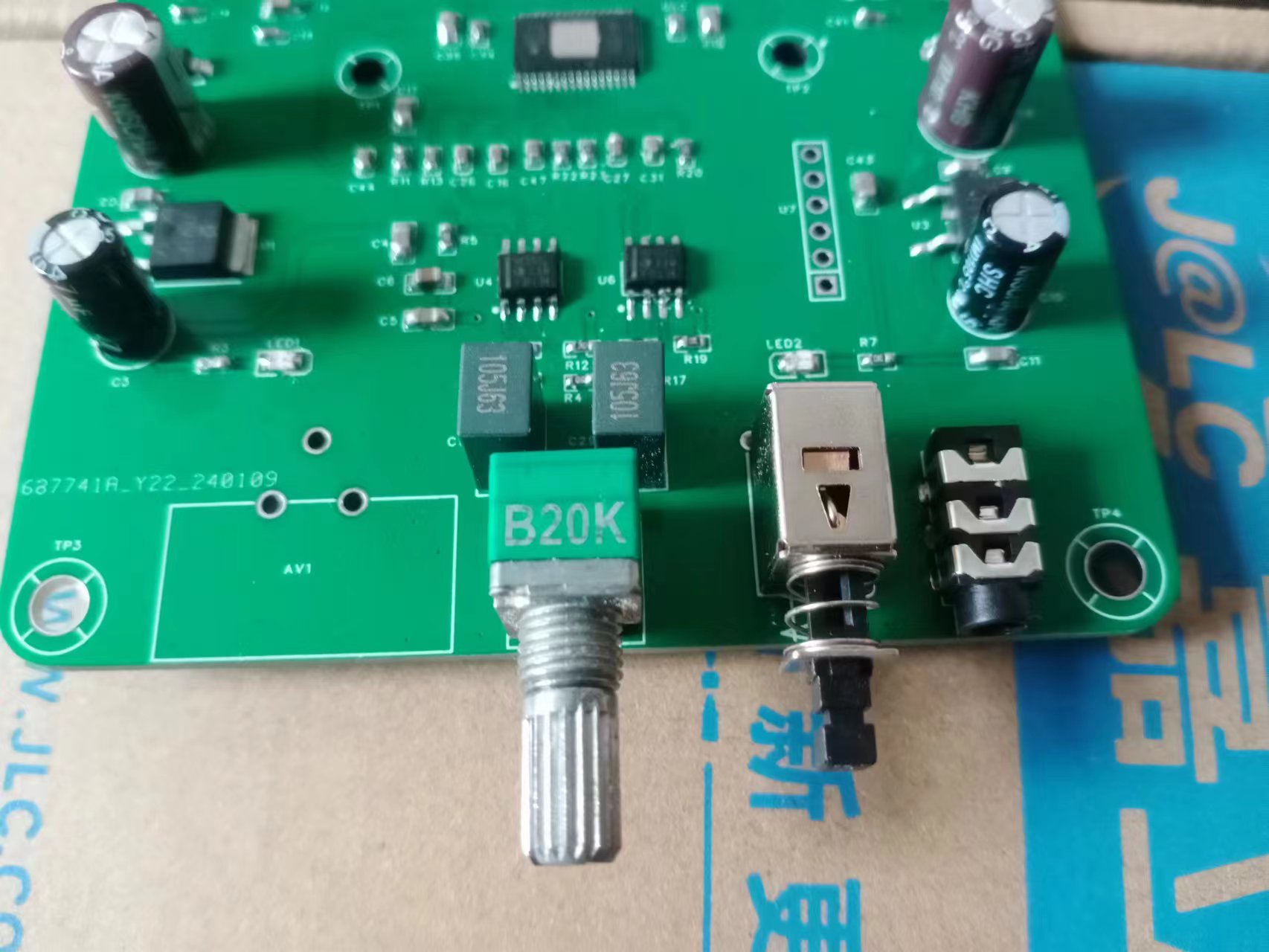
notes: The outer casing cannot be used directly and needs modification!
d985e42fbcec52ae61095dd1819ad855.mp4
8a801ce6f8a13449d5ae0558fd4b5bd8.mp4
PDF_DIY Mini Speaker.zip
Altium_DIY Mini Speaker.zip
PADS_DIY Mini Speaker.zip
BOM_DIY Mini Speaker.xlsx
96255
SGL8022W Card Light
The card reading light based on the SGL8022W has two versions with touch-controlled LED brightness
: one focusing on aesthetics and the other on practicality.
Only the aesthetic version was ultimately manufactured using a PCB.
Cause: ~~It was my classmate's birthday, and I wanted to make him a gift during LCSC's "Warm Winter Creations for the New Year" event. LCSC happened to be holding a "Warm Winter Creations for the New Year" contest, and I happened to have a chip I wanted to make a touch lamp, so I took the opportunity.
Thus, this touch lamp project came about.
Planning:
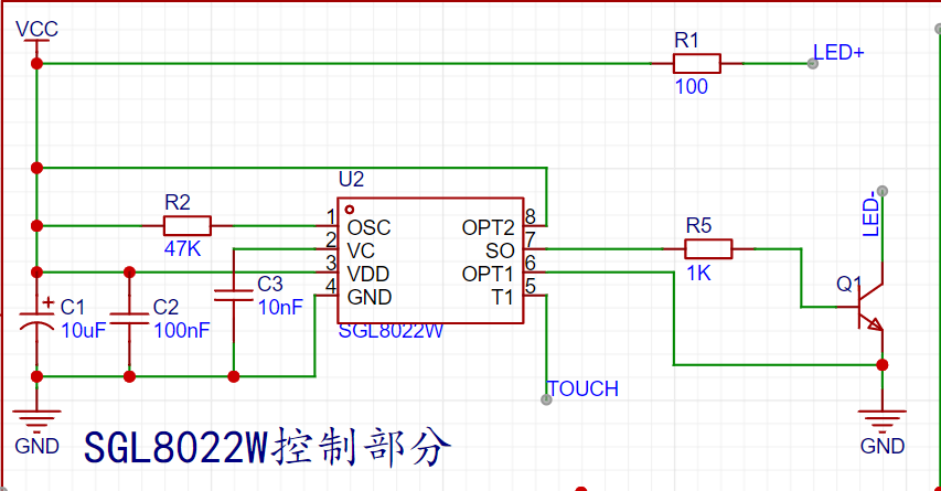
Main Controller: Since it's a touch lamp, it definitely needs to support touch. After researching online, I decided to use the SGL8022W as the main controller, which directly supports touch. (SGL8022W chip manual: https://item.szlcsc.com/82803.html)
Power Supply: The first version decided to use a TP4056 (chip manual: https://item.szlcsc.com/772193.html) + 18650 for power supply, plus a USB 6PIN for charging the 18650 and powering the lamp. The second version uses a CR2032 power supply plus a USB 6PIN power supply scheme. The first version used a Schottky diode circuit for automatic power switching, but the second version, due to laziness, simply changed it to manual power switching (dog head).
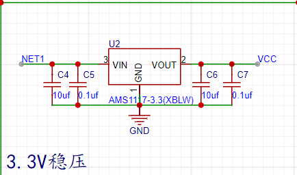
Voltage regulation: An AMS1117-3.3 (chip datasheet: https://item.szlcsc.com/20102431.html) was used for the 3.3V input voltage regulation scheme.
Schematic Diagram Section:
1. SGL8022W: Directly referenced the typical circuit provided in the chip datasheet, but considering that the control scheme does not need to be modified later, OT1 and OT2 were fixed as having no brightness memory and a gradual brightening/dimming mode
![image.png]
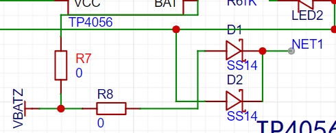
2. First version of TP4056: Referencing the typical circuit provided in the chip datasheet and the circuit design in https://blog.csdn.net/eletronicfish/article/details/131671126 (thanks to the author for the open source)
![TP4056 circuit.png]

3. Second version of CR2032: A total of 4 cells were used, with two cells connected in series and two connected in parallel
![battery.png]

4. AMS1117-3.3: Referencing the typical circuit provided in the chip datasheet and a tiny bit of memory (dog head)
![AMS1117-3.3.png]
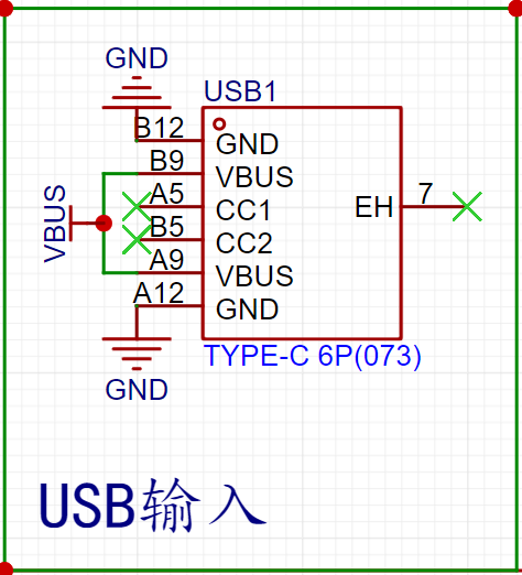
5. USB Input: USB_TYPE_C_6PIN
![USB.png]
6. LED Section: Eight white LEDs connected in parallel
![LED.png]

7. Manual Power Supply Selection: A mechanical selection mechanism was used
![Power Supply Selection.png]

8. Automatic Power Supply Selection: The circuit design in https://blog.csdn.net/eletronicfish/article/details/131671126 was referenced
![Power Supply Selection 2.png]
PCB Design
Component Packages: Most components were packaged in 0805 for easy hand soldering (dog head).
First version: Four-layer board. Signal traces were placed on the top and bottom layers. Inner layer 1 was VCC, and inner layer 2 was GND. Major components were placed on the top layer, such as the circuitry surrounding the TP4056 and the SGL8022W. The bottom layer contained eight LEDs and touch pads.
Touch Pads:
![Touch Pads.png]

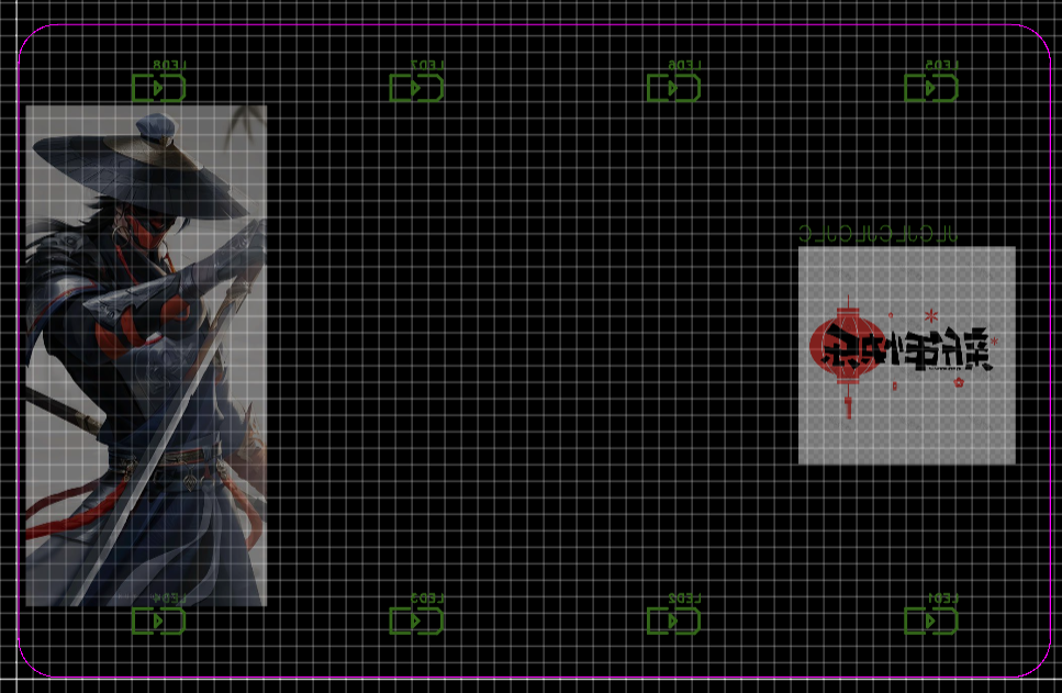
Second version: After learning that color silkscreen printing only supported two-layer boards, the design was redrawn. Except for a few places where thin lines were used, the line width was generally 30mil. A picture of Li Xingyun was added to the top layer (he's really handsome...)
![Top layer silkscreen.png]

A picture of Zhang Tian Anxing and Happy New Year was added to the bottom layer (~~to pass censorship~~)
![Bottom layer silkscreen.png]
3D shell:
First version: Too basic, too lazy to explain.
Second version: First, generate the shell frame using the board outline, then adjust the specific values:
![3D values.png]
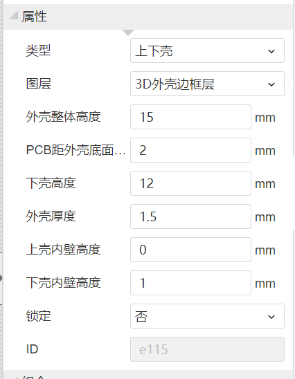
(depending on the situation)
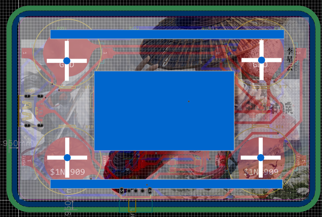
Next, cut grooves on the side according to the PCB:
![3D groove.png]

To allow light to pass through the bottom, cut grooves at the bottom
![Bottom groove.png]
To fix the PCB, add screw posts
![Bottom groove.png]
The shell is done (dog head)
SGL8022W characteristics
![SGL8022W.png]

Soldering:
Solder small components first, then large components. Be careful not to brittle the USB. The LED in the practical version is drawn backwards, too lazy to correct it. Remember to reverse it when you solder it yourself.
Video address:
https://www.bilibili.com/video/BV1g64y1w7y1/
PDF_SGL8022W Card Light.zip
Altium_SGL8022W Card Light.zip
PADS_SGL8022W Card Light.zip
BOM_SGL8022W Card Light.xlsx
96256
LM2596S voltage regulator
The LM2596S is a commonly used step-down voltage regulator chip widely used in electronic devices. It is a step-down regulator with switching function that can stably convert an input voltage (usually a higher DC voltage) to a lower output voltage.
Input Filter Capacitor: Connect the input power supply to the VIN pin of the LM2596S chip. To reduce noise and fluctuations in the input power supply, a suitable electrolytic capacitor is typically connected in parallel between the input power line and VIN. This capacitor is generally selected with a value of tens to hundreds of microfarads (µF).
Output Filter Capacitor: Connect the load requiring voltage regulation to the VOUT pin of the LM2596S chip. To reduce output voltage ripple and provide a stable power supply, a suitable capacitor needs to be connected in parallel at the output. The capacitance value is determined according to specific application requirements, with common values ranging from tens to hundreds of microfarads (µF).
Output Inductor: To improve conversion efficiency and reduce output ripple, a suitable inductor can be connected in series between the VOUT pin of the LM2596S chip and the output filter capacitor. The inductor value is generally between tens and hundreds of microhenries (µH).
Control Switch: The LM2596S chip has an internal switch used to control the switching time of the input voltage, realizing the buck regulation function. A suitable inductor is connected to the SW pin of the chip to control the conduction and shutdown of the switching transistor.

PDF_lm2596s voltage regulator.zip
Altium_lm2596s voltage regulator.zip
PADS_lm2596s voltage regulator.zip
BOM_lm2596s voltage regulator.xlsx
96261
electronic


 京公网安备 11010802033920号

 HLMP-4100-SX000


