The Luo Xiaohei-style voice-activated light can be turned on/off or have its color changed by speaking. Each one costs about two yuan. Because it uses a USB port, you can buy an adapter online to connect it to a phone.
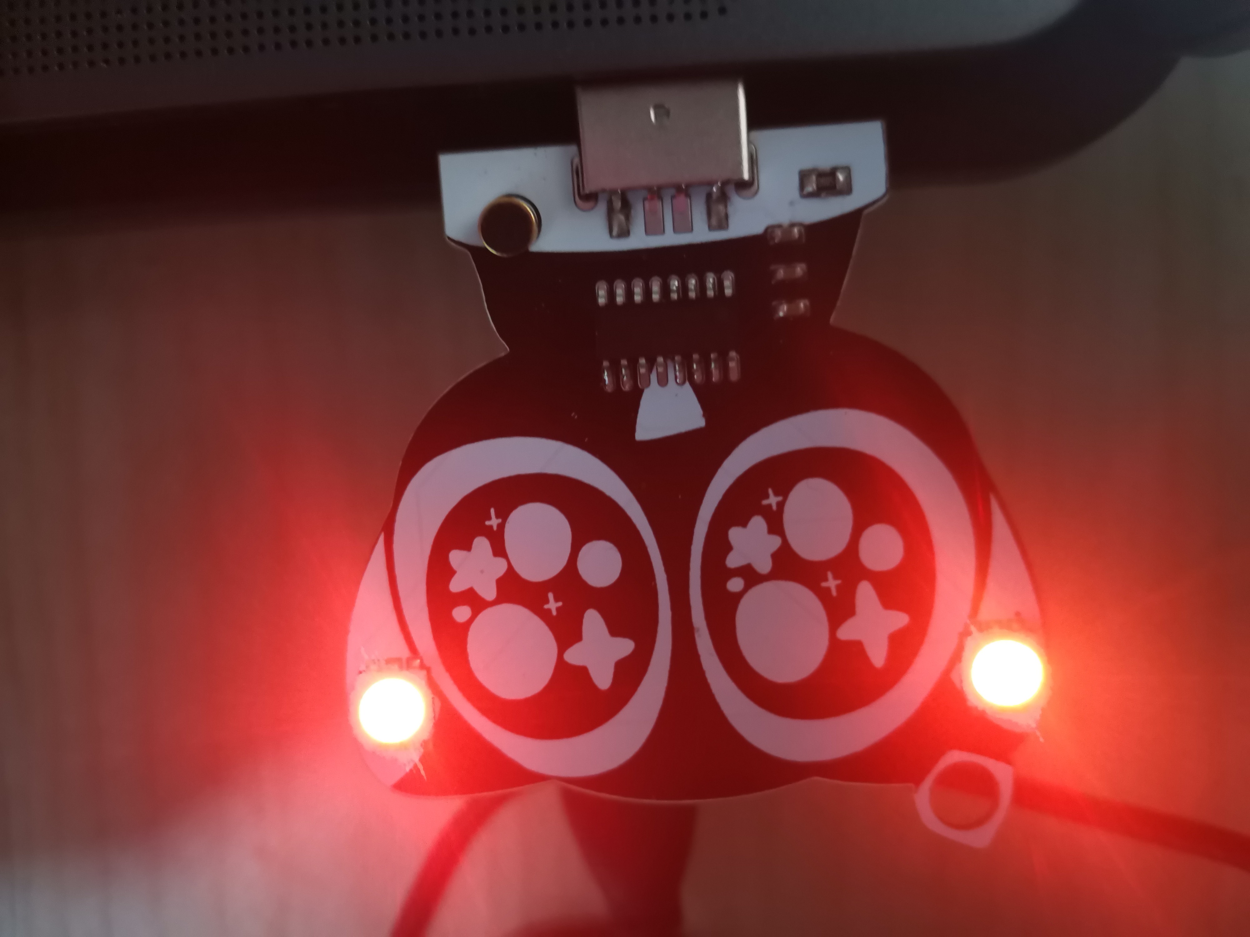
The light here isn't very bright because I drew two lights; you can draw only one for much brighter illumination.
An offline voice chip was soldered on for voice control. These chips are available on Taobao for 1.8 yuan each, but the shipping is a bit expensive. The chip programs are pre-programmed and can be soldered directly.

PDF_Luo Xiaohei Ornament Voice Lamp.zip
Altium_Luo Xiaohei Ornament Voice Lamp.zip
PADS_Luo Xiaohei Pendant Voice Lamp.zip
BOM_Luo Xiaohei Pendant Voice Light.xlsx
96541
Online Environmental Monitoring System (MQTT Protocol)
The detected concentrations of carbon dioxide and formaldehyde in the environment are uploaded to Alibaba Cloud servers and finally displayed on the mobile app.
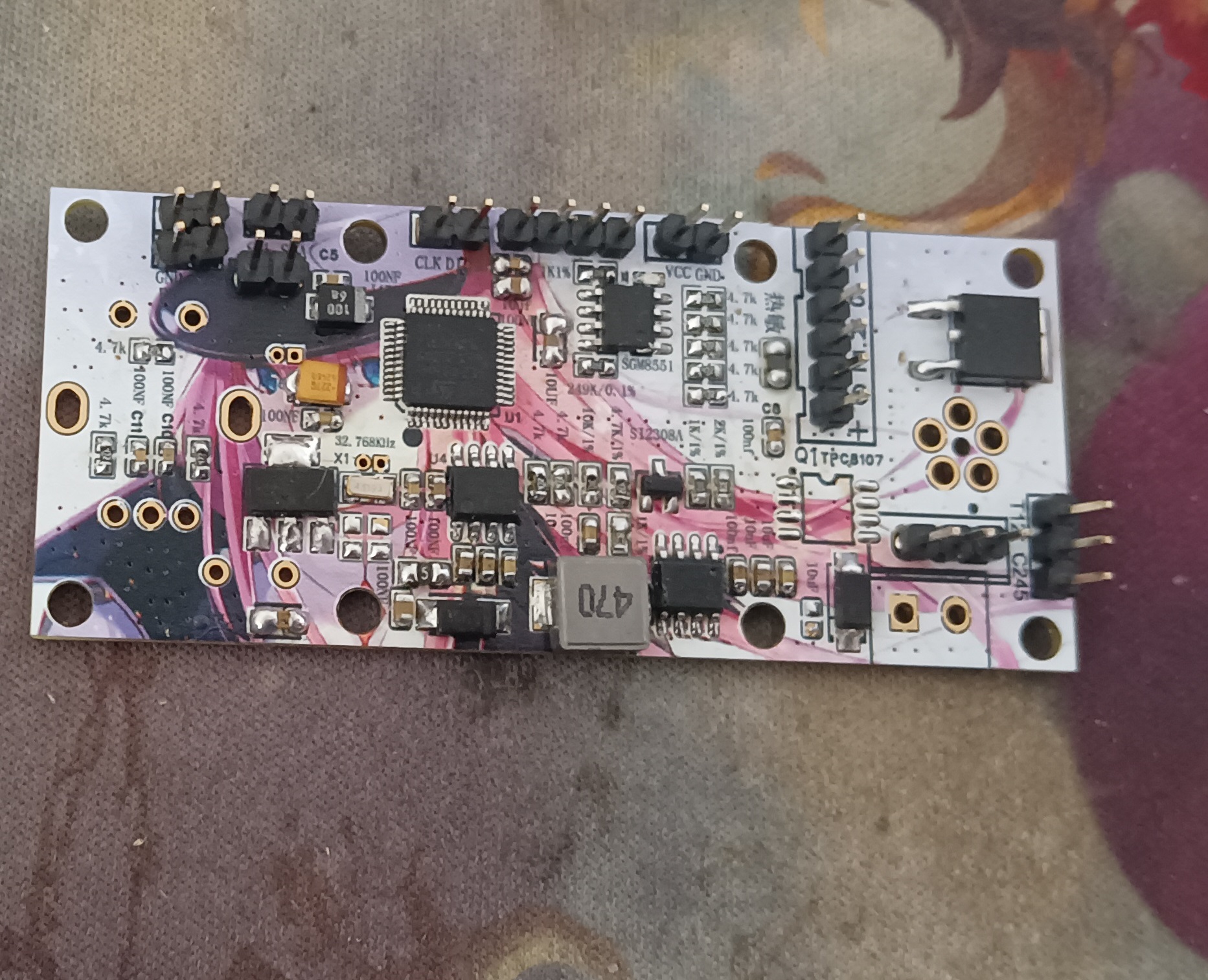
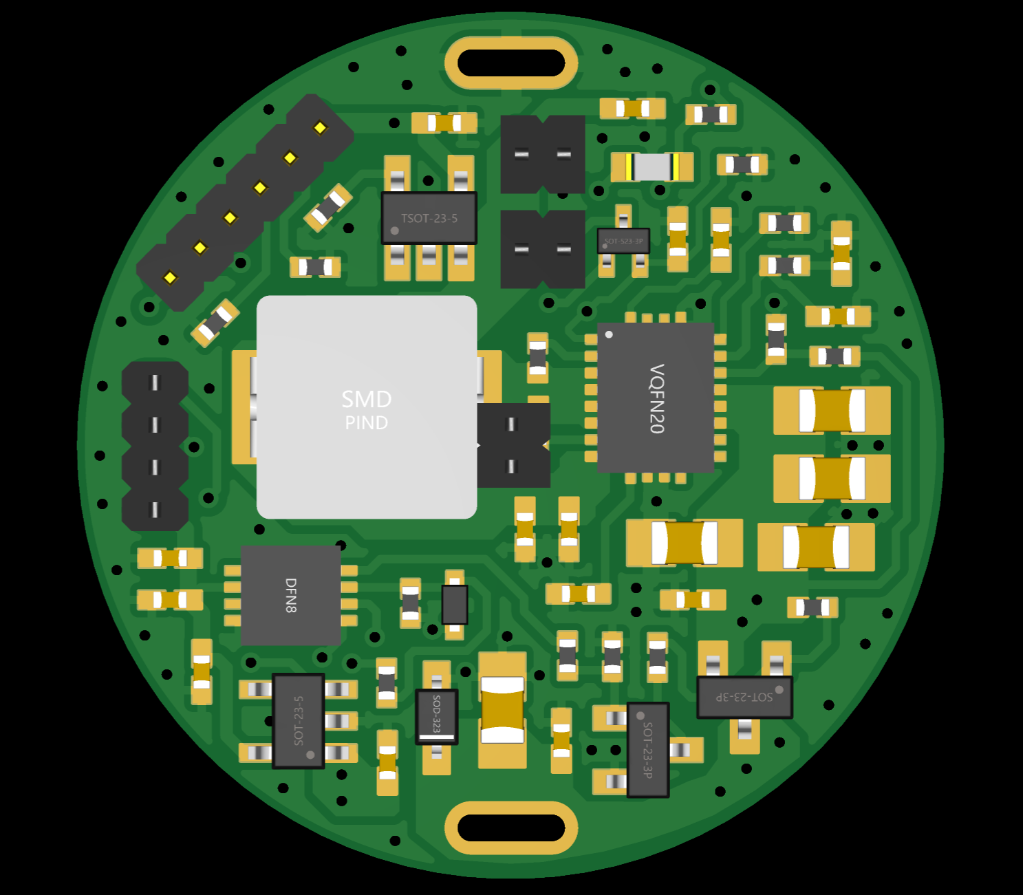
The main controller is Liangshanpai (GD32F470). It works with the ESP8266 (MQTT protocol AT commands) and SGP30 air quality sensor to upload the carbon dioxide and formaldehyde concentrations in the environment to the Alibaba Cloud server, which then displays the data on the mobile app!
Espressif Systems AT command set (opens in a new window)
Alibaba Cloud website (opens in a new window)
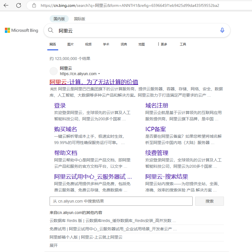
Those without an account need to register!
If you have already used it and activated the IoT platform but not the Feiyan platform (Life IoT platform), you need to register a new account.
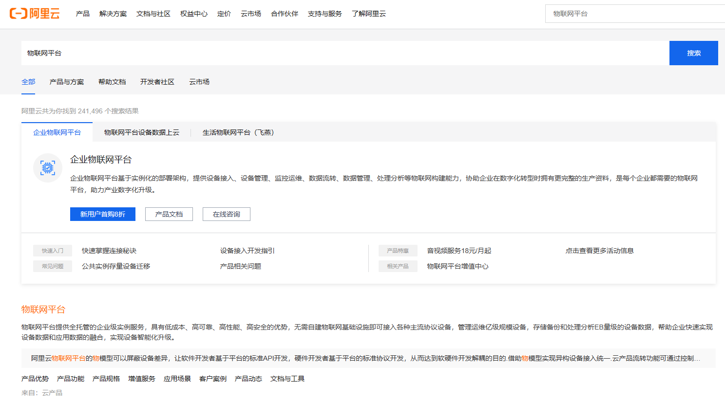
IoT product selection (important)
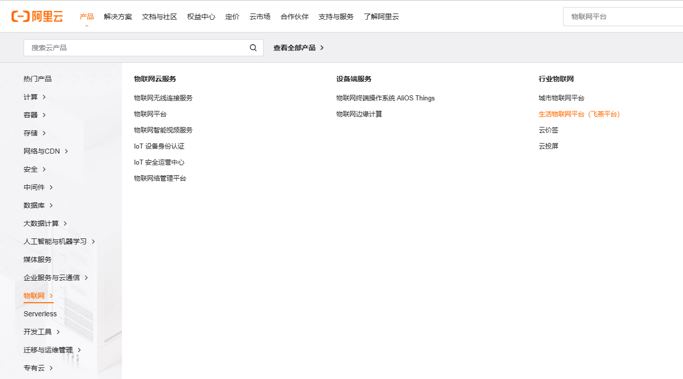
: You must select the Feiyan platform (Life IoT platform) first. Alibaba Cloud Feiyan platform (opens in a new window)
Do not activate the IoT platform first. IoT platform link (opens in a new window)
!!!!!!!!!!! Otherwise, you will not be able to register for the Feiyan platform.
The remaining operations can be viewed in Case 2 of LCSC Liangshanpai Module Porting - Part 1: Wireless Communication Module Porting (ESP-01S). After completing this, return here to continue the remaining parts!!!
To view MQTT connection parameters
, after creating the project on the Feiyan platform, to connect to the Alibaba Cloud platform via ESP8266 (ESP0-1S), you need to create the MQTT protocol parameters for your product.
Specific parameters can be viewed on the Alibaba Cloud IoT Platform (open in a new window).
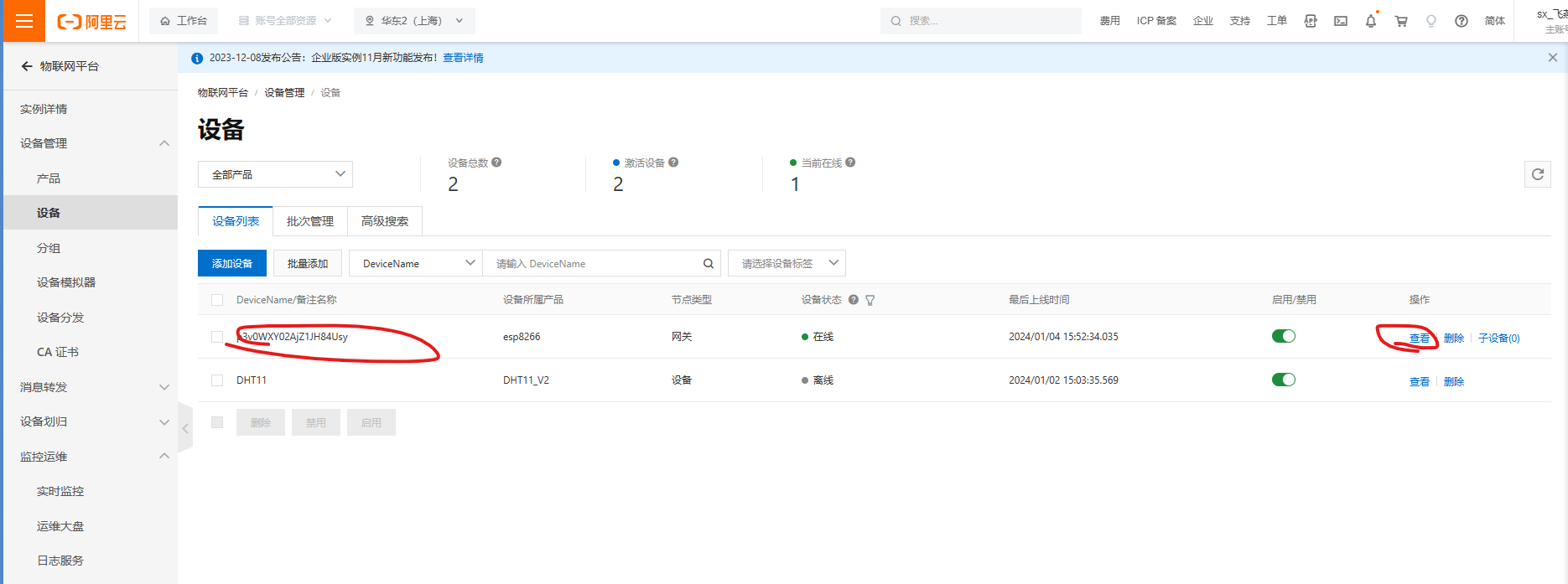
Click on your product in the above image (or directly click on the device name).
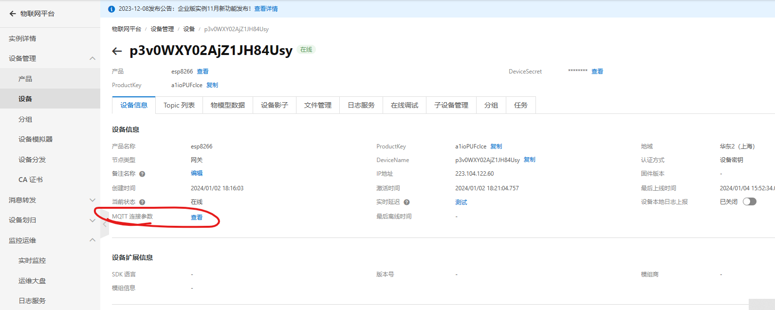
On this interface, click on MQTT parameter viewing to connect to Alibaba
Cloud Espressif Systems via AT commands (open in a new window).
PS: If you have a Liangshanpai development board and are only learning this project, you can directly use DuPont wires for connection; no board is needed.
esp8266 connecting to Alibaba Cloud.rar
Module Introduction.mp4
APP demo.mp4
Serial port data viewer.mp4
PDF_Online Environmental Monitoring System (MQTT Protocol).zip
Altium Online Environmental Monitoring System (MQTT Protocol).zip
PADS Online Environmental Monitoring System (MQTT Protocol).zip
BOM_Online Environmental Monitoring System (MQTT Protocol).xlsx
96542
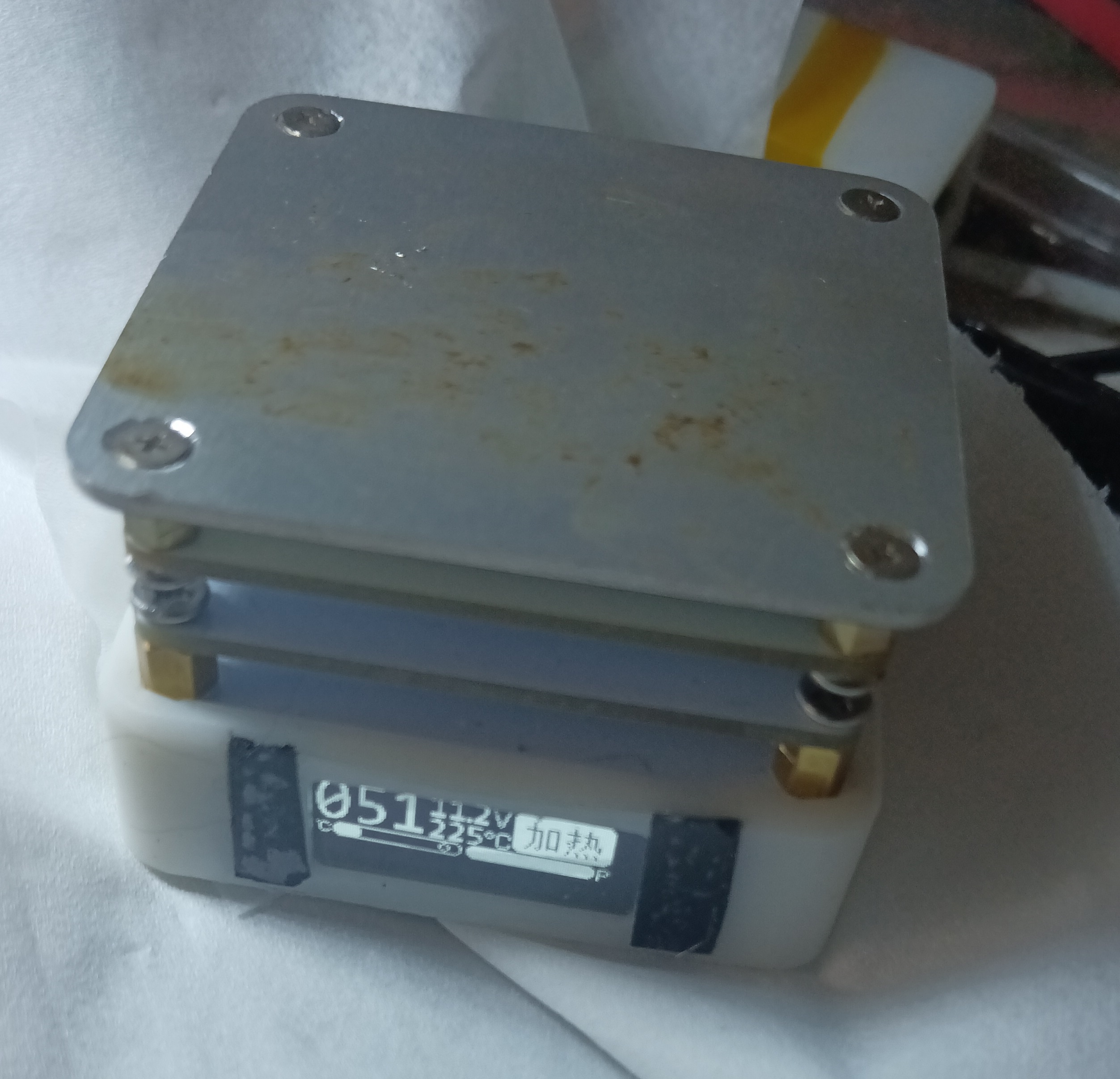
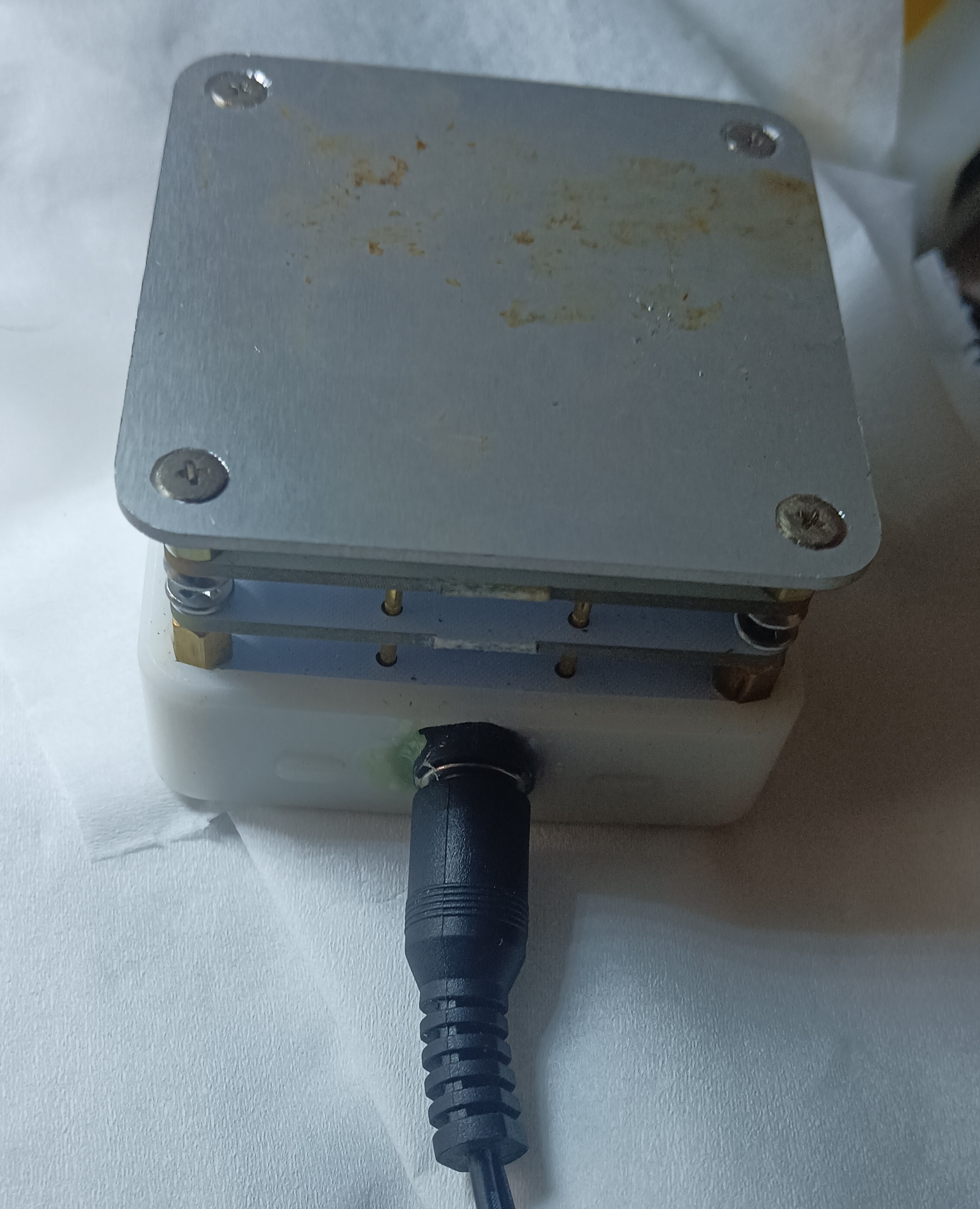
Constant temperature heating
Constant temperature heating
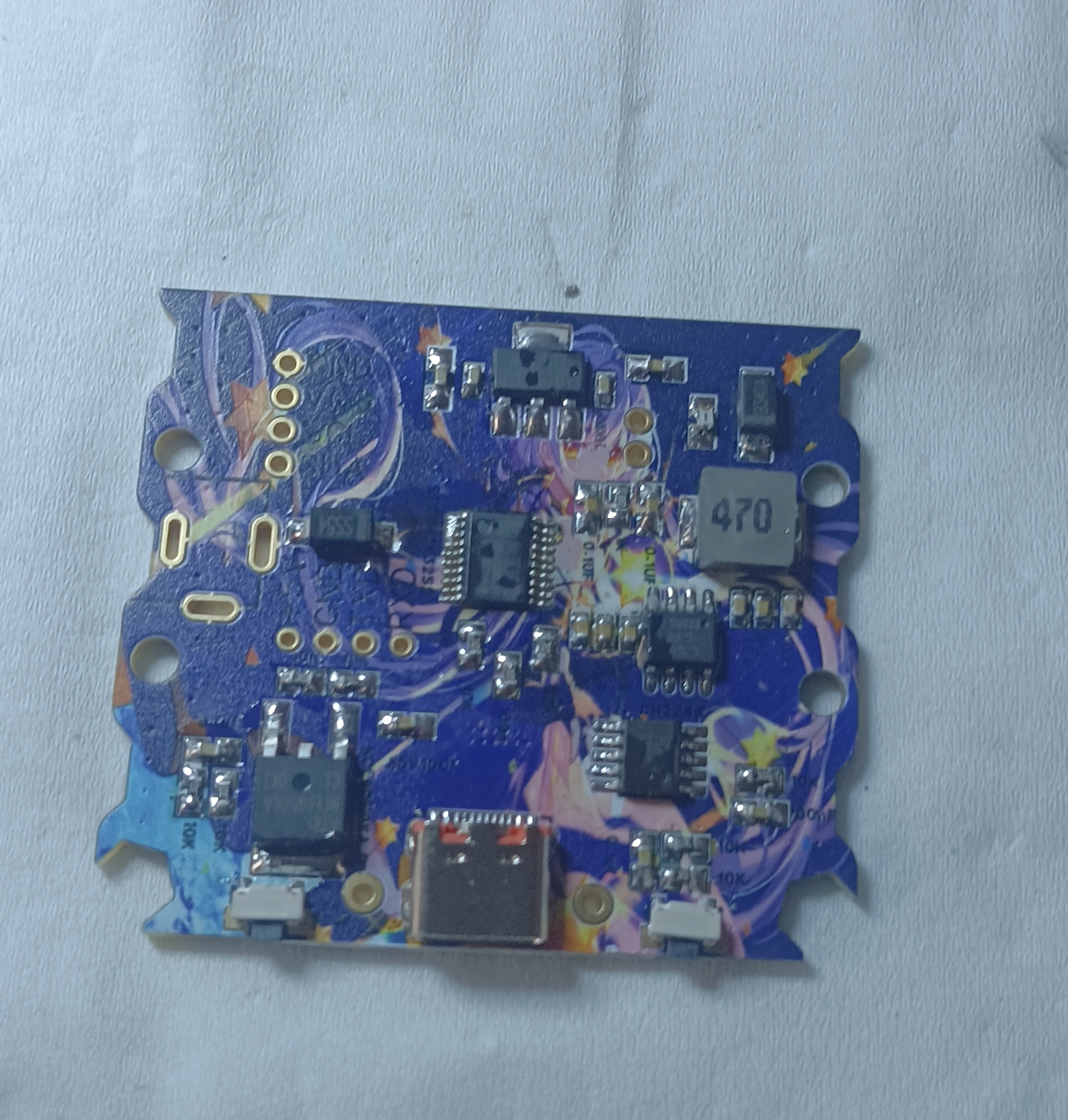
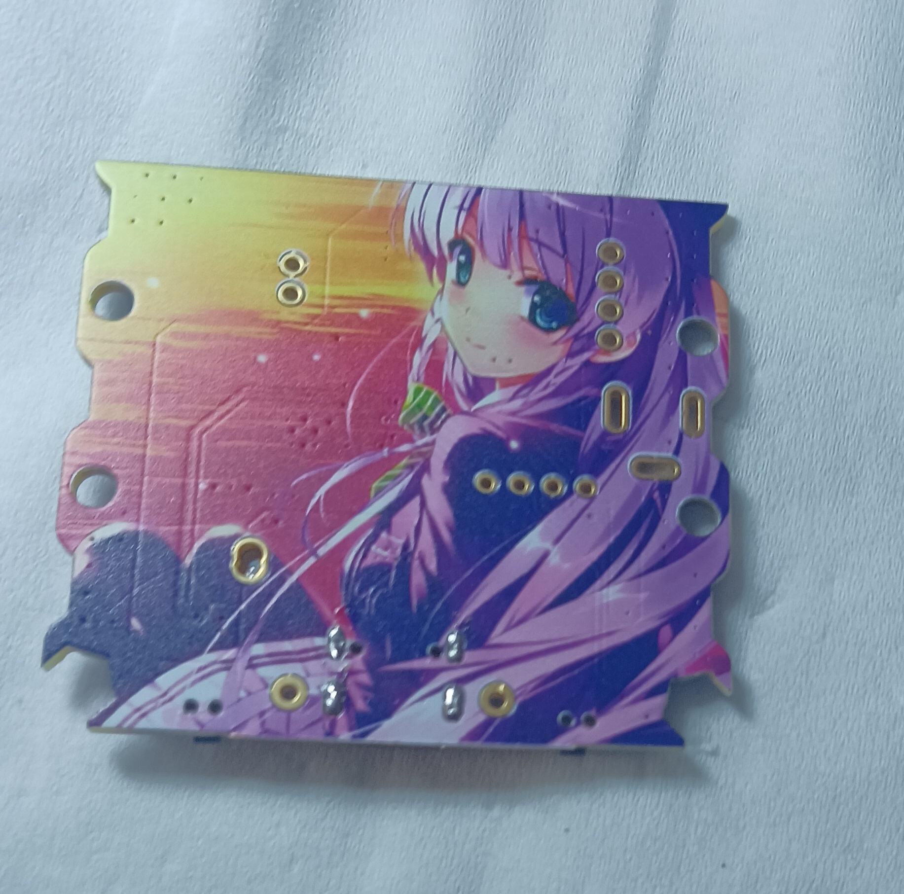
The heating element is heated at a constant temperature using an STM32F103CBT6 microcontroller to control the switching of the MOSFET.
It is compatible with various MOSFETs and operational amplifier circuits.


1.3.hex
PDF_Constant Temperature Heating.zip
Altium_Constant Temperature Heating.zip
PADS_Constant Temperature Heating.zip
BOM_Constant Temperature Heating.xlsx
96543
Smart hand warmer
Smart hand warmer
PDF_Smart Hand Warmer.zip
Altium Smart Hand Warmer.zip
PADS Smart Hand Warmer.zip
BOM_Smart Hand Warmer.xlsx
96544
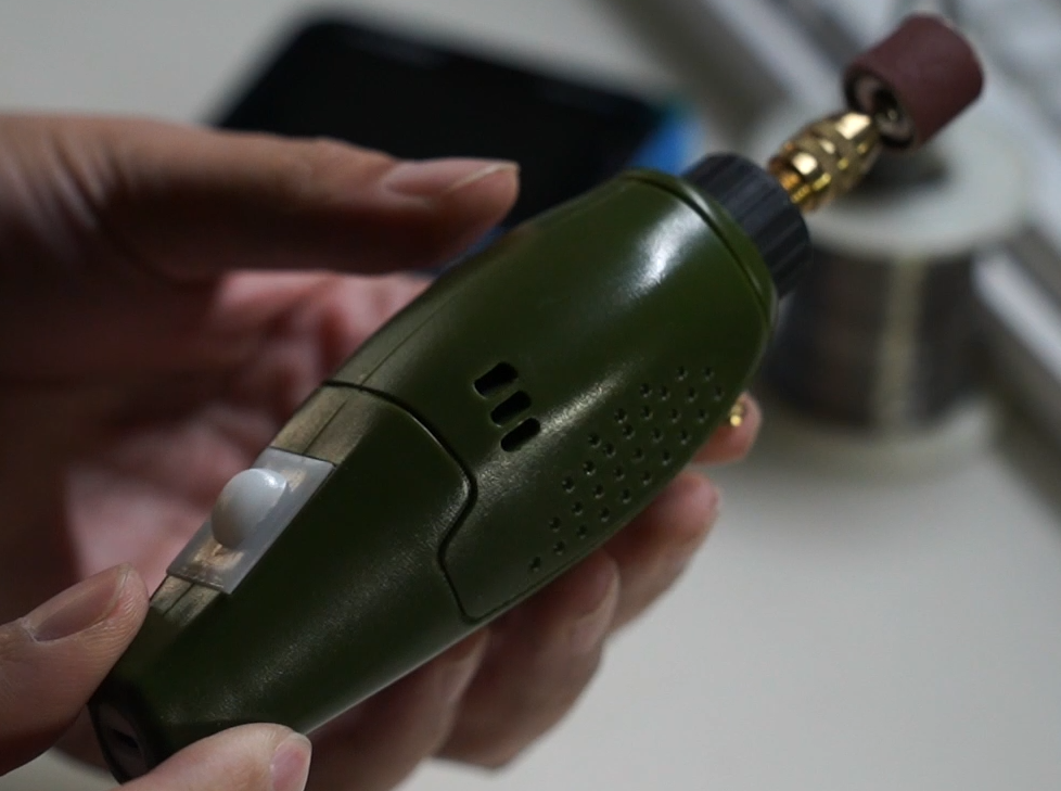
Detonate a bomb, modify a wired electric grinder to a lithium battery, and grind freely everywhere.
Corded electric mill converted to lithium battery
Use version 1.1; version 1.0 has issues.
The tutorial video is here:
https://www.douyin.com/user/self?modal_id=7319860540384218402 .
There are also some 3D printed parts
, such as fitting a Type-C port into a DC socket.

This is a control board soldered onto the motor; the vibration is a bit too much, so I don't recommend soldering it directly onto the motor.

Assembly has begun.

The finished product looks like this (like a dangling object).
power_block.SLDPRT
power_block.STL
power_jack.SLDPRT
power_jack.STL
switch_cover.SLDPRT
switch_cover.STL
switch_holder.SLDPRT
switch_holder.STL
PDF_Explode a Bomb: A Wired Electric Grinder Modified with Lithium Battery - Grind Freely Anywhere.zip
Altium_Explode a Bomb Wired Electric Grinder Modified to Lithium Battery, Grind Freely Anywhere. zip
PADS_Explode a Bomb Wired Electric Grinder Modified to Lithium Battery: Grind Freely Anywhere. (zip)
96547
[Joint Laboratory] STC32-based Miniature Car | Taiyuan University of Technology
STC32G WiFi-based tracked vehicle
Background:
In modern society, robots and related technologies are widely used in many fields such as machinery, electronics, transportation, national defense, and agriculture. With the extensive and in-depth development of robot research, robots are no longer limited to manufacturing but have been extended to non-manufacturing fields such as mining, rescue, and hydropower system maintenance, with mobile robots being a prime example. WIFI wireless communication has the advantages of large coverage area and high transmission speed, enabling robots to work in some hazardous environments. Intelligent vehicles, due to their advantages such as automatic tracking, obstacle avoidance, and controllable driving, can meet the requirements of various environments and tasks. Furthermore, their low manufacturing cost and stable operation make them popular in many hazardous operations and industrial settings. China has begun to rapidly focus on the development of the robotics industry, establishing many high-level research and development bases, laying the foundation for innovation in robot development in the new century. The intelligent vehicle uses an STC32G series microcontroller as its control core. It acquires external environmental signals through infrared sensors, is driven by a motor drive module, and uses a camera to collect video information. The design block diagram of the intelligent vehicle mainly includes a power supply module, obstacle avoidance module, automatic tracking module, motor drive module, camera, WIFI module, and microcontroller.
Research Significance:
Through the study of the STC32G tracked vehicle, it can be understood that intelligent vehicles can autonomously complete tasks without human intervention by using sensors to make judgments and analyses in their environment.
Requirements Analysis:
Functional Requirements
: 1. Use the STC32G microcontroller. The STC32G is a common embedded system controller with strong performance and flexibility.
2. Wireless Control: Control the vehicle's forward, backward, and left/right rotation via WIFI.
3. Obstacle Avoidance: Detect objects using ultrasonic waves to achieve obstacle avoidance.
4. Sounding: Achieve sounding by detecting high and low electrical frequencies using an active buzzer. 5.
Distance Measurement and Parking: Achieve parking by measuring distance using the NRF2401 module.
Design Constraints (Hardware, Time Cost, and Economic Cost, etc.) :
Hardware Design Constraints
: 1. Sensor Selection: Select high-precision, low-cost, and high-performance sensors to control the vehicle and for data storage and transmission.
2. Signal Acquisition and Processing: Design suitable circuits to acquire and process the analog signals output by the sensors.
3. MCU Processor Selection: The STC32G12K128 is used as the core. Compared to the 51 microcontroller, the STC32G can accommodate smaller systems and is faster.
4. PCB Layout and Packaging: During hardware design, the layout and packaging must be checked for rationality and correctness.
5. Battery Management: A 12V battery is used for power; the stability and efficiency of the power supply must be ensured.
Time Costs:
1. PCB Design Time: This includes schematic design, package import, and PCB design.
2. PCB Production Time: Orders are placed using JLCPCB, and receiving the order requires a certain amount of time.
Solution Design :
The overall hardware solution design
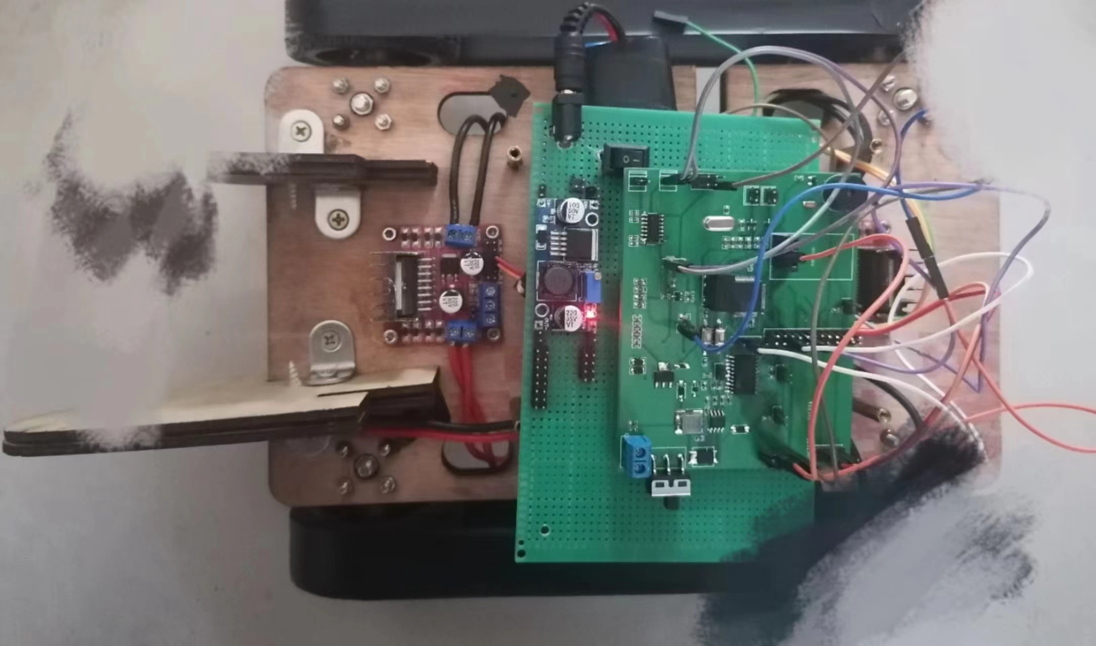
uses the STC32G12K128 as the core. Compared to the 51 microcontroller, the STC32G can accommodate smaller systems and is faster. The system outputs PWM to control the motor; detects obstacles at a distance of 15cm; uses serial communication for debugging the intelligent car, with the baud rate set to 115200; processes and judges received commands; connects to and controls the WIFI module, enabling the car to move forward, backward, and rotate left and right. For
the motor drive
, to allow the PC to control the car's speed and meet the DC motor's drive voltage requirements, the L293DD motor driver chip is used to power the DC motor.
The motor status and STC32G input are shown in the table. The motor driver has two power input interfaces, one 5V and the other 12V. During use, the 12V interface input voltage must be greater than 7V, while the 5V interface can power the microcontroller
.
The servo
motor has three input lines: the red one in the middle is the power line, and the black one on one side is the ground line. These two lines provide the servo motor with the most basic energy guarantee, mainly for the motor's rotation. There are two power supply specifications: 4.8V and 6.0V, corresponding to different torque standards, i.e., different output torques. The 6.0V supply corresponds to a larger torque, depending on the application conditions. The other wire is the control signal wire; Futaba's is generally white, while JR's is generally orange.
The PWM servo controls
the servo with a 20ms pulse width modulation (PWM) signal. The pulse width ranges from 0.5ms to 2.5ms, corresponding to a linear change in the servo head position from 0 to 180 degrees. In other words, providing a certain pulse width will keep its output shaft at a corresponding angle, regardless of changes in external torque, until a pulse signal of a different width is provided, at which point it will change its output angle to the new corresponding position.
Summary and Outlook
: 1. Ultrasonic obstacle avoidance is not effective. In some cases, obstacle avoidance fails when ultrasonic waves detect objects.
2. WIFI communication sometimes drops. During communication, there are frequent connection failures or inability to receive data, requiring optimization.
3. The appearance needs improvement. Further design improvements are possible.
Altium_project_2023-11-24_14-38-48_2023-12-28.zip
PDF_【Joint Laboratory】STC32-based Small Car_Taiyuan University of Technology.zip
Altium_【Joint Laboratory】STC32-based Mini-Car_Taiyuan University of Technology.zip
PADS_【Joint Laboratory】STC32-based Small Car_Taiyuan University of Technology.zip
BOM_【Joint Laboratory】STC32-based Small Car_Taiyuan University of Technology.xlsx
96551
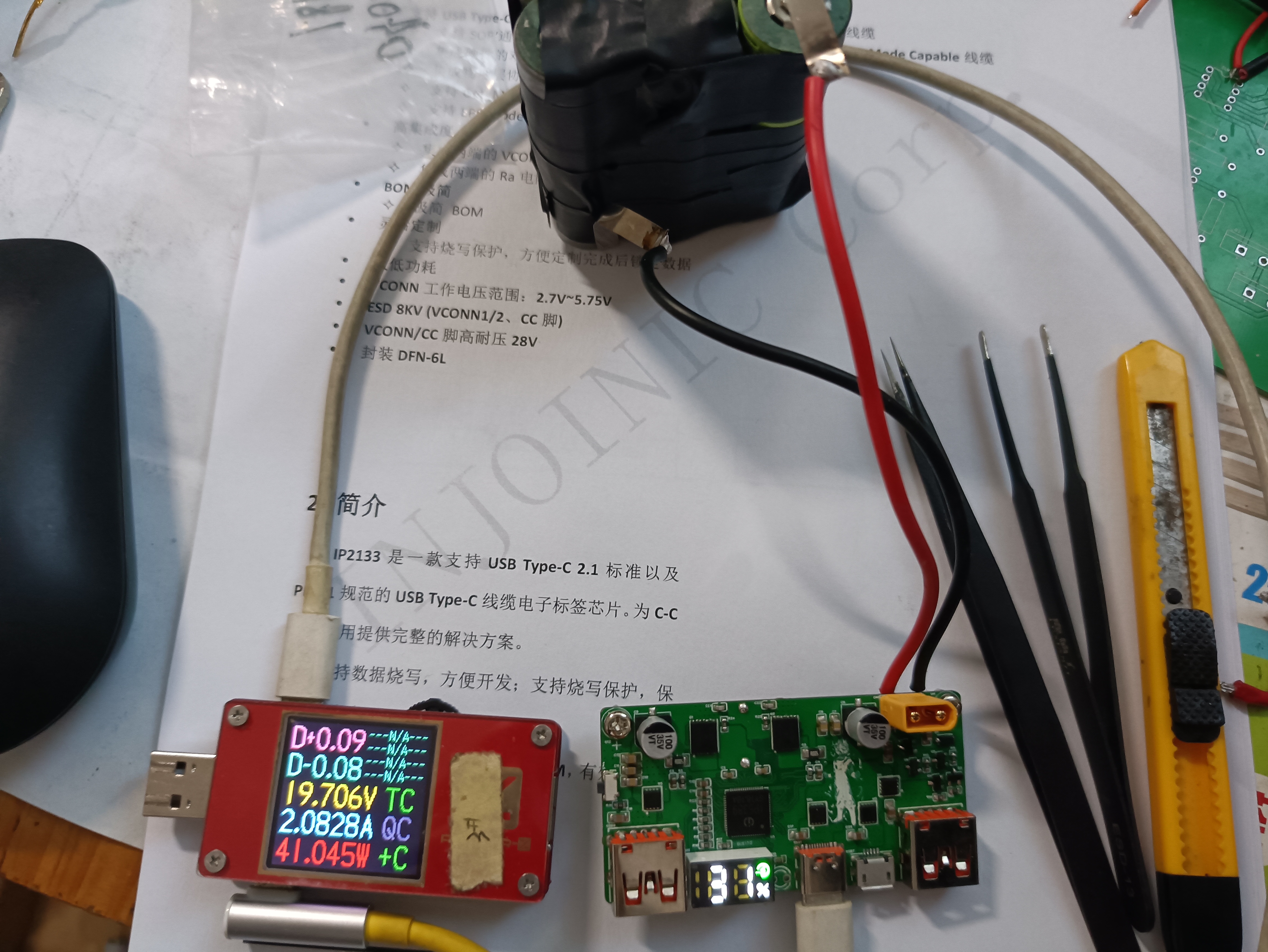
PD100W bidirectional fast charging pad
Based on the Ingenic IP5389, it supports bidirectional PD 100W fast charging, supports fast charging protocols such as QC3.0+, FCP, AFC, SCP, VOOC, PD3.0, and Apple BC2.1, and supports 2/3/4/5 cells connected in series with an efficiency of up to 97%. The digital tube displays the battery level.
This mini-sized board supports multiple protocols
and is ideal for DIY projects.
It features a rich array of output ports: two USB-A, one Type-C, and one micro-USB.
For high-power applications, a cooling system is required.
The NTC thermistor was placed next to the MCU during layout, necessitating a cooling solution.
The board includes DIP switches for battery capacity adjustment, battery string count, and battery charging voltage.
No resoldering of corresponding resistor values is necessary; simply toggle the switches to the appropriate positions for easy adjustment.
The board's compact design allows for the placement of larger batteries, enhancing DIY convenience.
A flashlight function has been added; a 2-second press turns it on, and another 2-second press turns it off.
Charging current, voltage, and power display functions will be added later; this
is still under development.
WeChat image_20231225015226.jpg
WeChat image_20240103162850.jpg
WeChat image_20240103162852.jpg
100W Power Bank Motherboard Setup Instructions.pdf
PDF_PD100W Two-Way Fast Charging Board.zip
Altium_PD100W Two-Way Fast Charging Board.zip
PADS_PD100W Two-Way Fast Charging Board.zip
BOM_PD100W Two-Way Fast Charging Board.xlsx
96552
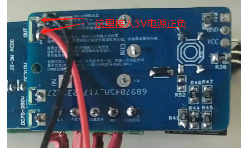
ESP01 Smart Switch
This miniature smart switch based on ESP01 can be controlled via infrared remote control or an app. It also allows for voice control of the relay when paired with a main control board. The entire board costs less than 10 yuan. Through hardware and software integration, it eliminates the power-on bounce problem of the ESP01 pins.
If this board is connected to a 220V input, two-thirds of the board will carry 220V. Those without relevant experience with high-voltage electricity should not operate it while it is energized, as there is a risk of electric shock. If electric shock occurs due to carelessness, the consequences will be severe.
It can be used in any circuit requiring switch control, in conjunction with existing or newly installed switches, to achieve intelligent voice and infrared remote control control of the switch. The target of the switch control can be lights, televisions, water heaters, and other circuits requiring on/off functionality.
This board, when used with the main control board (https://oshwhub.com/mynewworldyyl/esp32s3-xiang-mu), can establish a master-slave relationship, allowing the switch to be controlled via voice or infrared remote control from the main control board, similar to a slave device in Tmall Genie. The configuration methods for this board are basically the same as those for the main control board; please refer to https://oshwhub.com/mynewworldyyl/esp32s3-xiang-mu for relevant instructions.
The circuit design of this board is relatively simple, and related components can be purchased inexpensively on Taobao.
The pin assignment is as follows:
GPIO0 connects to the relay, GPIO2 connects to the button, and RX connects to the infrared sensor
. Only GPIO0 needs to be configured in the APP; the button and infrared sensor are already forcibly bound.
An infrared remote control is used; in fact, any NEC protocol remote control can be used. The code value corresponding to the remote control button needs to be configured in the APP when configuring the command ID.

The connection method is similar to a traditional dual-control switch.

The above is a wiring diagram of two switches controlling one light. We only need to replace one of the switches on the main control board with the relay. The relay's "normally open" and "normally closed" outputs correspond to L1 and L2 of the switch above, respectively. Actually, normally open and normally closed outputs can also correspond to L2 and L1. Three relays can control three lights respectively.
The board has a 5V external power supply port, allowing direct input of 5V without needing an external 220V power supply. This facilitates testing and verification, and in actual use, it can control non-220V circuits.
Firmware and flashing commands.zip
esp01 micro switch.mp4
PDF_ESP01 Smart Switch.zip
Altium_ESP01 Smart Switch.zip
BOM_ESP01 Smart Switch.xlsx
96554
electronic


 京公网安备 11010802033920号

 162-99630-7051C


