I. Introduction
Based on the GD32F103RB microcontroller, this code supports dual-channel oscilloscope, dual-channel DAC, single-channel PWM, and lithium battery power; it also supports Lissajous figure display.
The code was released hastily and definitely contains some bugs, which will be fixed later when time permits; it's open source for now. The code borrows some features from RT-Thread, whose framework is truly excellent.
Open source code address: https://gitee.com/orange_gg/dso_1-m.git
Parameters:
Screen
240*240 1.3-inch
single-chip microcontroller
GD32F103RBT6
acquisition and
display
dual-channel
DAC
dual-channel DAC (T-type resistor network)
sampling rate (maximum 1MHz)
sine wave, triangle wave, sawtooth wave
AC and DC coupling
1-25KHz
input voltage range -2V~+6V
PWM
duty cycle adjustable 1-99%
Lissajous figure (xy mode)
1-100KHz
frequency meter
power supply
5V-typec
voltage peak-to-peak
lithium battery
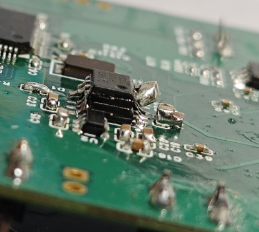
II. Main hardware analysis
1. Analog front end analysis:

U9 is used for AC-DC coupling switching;
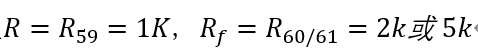
R48, R49, R50 resistor network for input gain:

U4.2 performs inverting proportional amplification, then
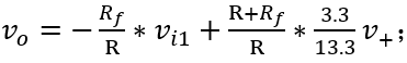
here

to here


2. T-type resistor network DAC:

digital to analog conversion can be achieved using only a simple resistor network (T-type network), which mainly consists of a T-type resistor network, operational amplifier, reference power supply and analog switch.
This design is somewhat limited, only implementing a DAC output of 0-3.3V (actually, it doesn't reach 3.3V, mainly depending on the op-amp performance and the microcontroller's GPIO driving capability). The reference power supply is provided by the microcontroller's GPIO high level. U5.2 in the diagram is only used to follow the output and enhance its driving capability. This DAC uses 10 GPIOs for driving, with a resolution of 1024. This design includes two DACs (DAC0 and DAC1) occupying 20 GPIOs.
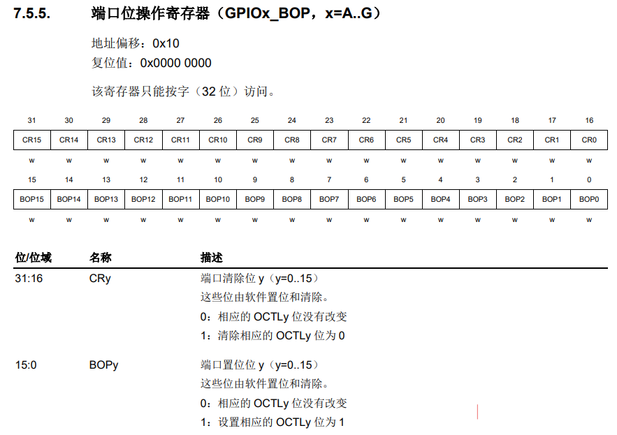
Note: the drive signals for DACs in the same group must be placed on at least the same group of GPIOs to use DMA to move data and output waveforms. For example, ADC0_D0-ADC0_D9 can all be placed on GPIOB, in different orders. Using GPIOs in the same group allows the DMA peripheral address to use GPIOx_BOP. Furthermore, the CRy bit of GPIOx_BOP, in conjunction with the BOPy bit, can perform set and reset operations on any GPIO in the same group without affecting other GPIOs in the same group. See the diagram below for register descriptions.
3. Charging and Discharging:
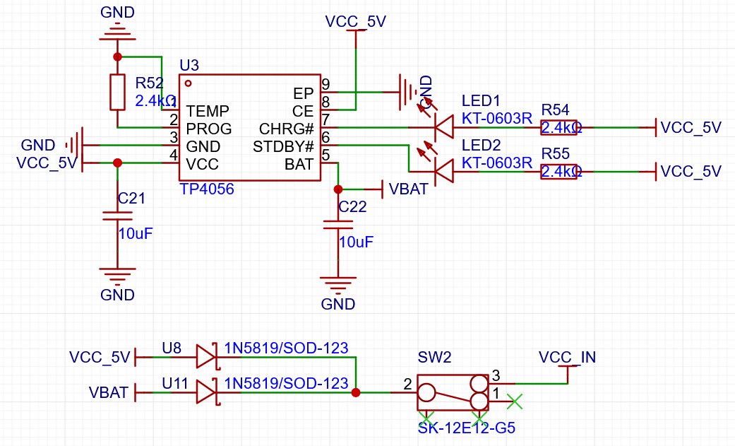
Charging and discharging lithium batteries is relatively simple. Refer to the datasheet for details. The charging current is adjusted by R52, and the input current is prevented by a diode, easily achieving battery VBAT or VCC_5V switching. Using a MOSFET would improve battery energy utilization; the circuit shown in the diagram below is recommended to replace the dual diodes.

4. Pitfalls:
① Negative Voltage Output: Using a TP7660H chip, the output is -3.3V, but the actual output is around -2V. Since this oscilloscope is dual-channel, using two op-amps, the current is high, causing the TP7660 output to be undriveable. Fortunately, the 7660 is a charge pump solution, which can be easily paralleled. Parallelizing two TP7660s achieves -2V, easily overcoming the issue. (No changes were made to the schematic.)
② TP4056 Enable/Disable: A major blunder! During debugging, it was discovered that the battery wasn't charging, and the enable pin in the schematic was grounded. I didn't want to build a new board, so I just used a jumper wire. (The schematic has been modified.)

Other hardware will not be introduced, as it is basically the same as that explained in the training camp videos.
III. Demonstration
1. Waveform Display:
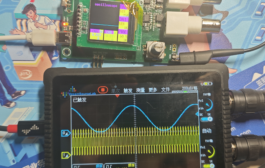
Dual-channel waveform display, frequency measurement, peak-to-peak value measurement, AC/DC coupling mode selection, maximum sampling rate of 1MHz (dual channel). The GD32F103RBT6 has two ADCs, one for each of the two sampling channels. With the help of timer DMA, dual-channel synchronous automatic sampling can be achieved (1MHz is not the limit sampling frequency). Theoretically, a single-channel sampling rate of 2MHz can be achieved by using ADC alternating sampling, but this method was not used here. The effect diagram is shown below.

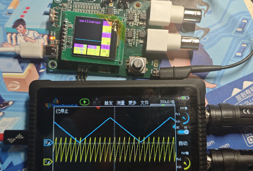
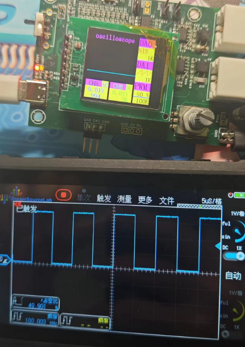
AC/DC coupling output selection is controlled by a solid-state relay program. In Figure A below, the green waveform CHB is the AC coupling waveform, and the blue waveform CHA is the DC coupling waveform. Figure B is a square wave waveform. The severe distortion is due to an unsuitable coupling capacitor. Replacing it with a 100nF capacitor will solve the problem, as shown in Figure C.
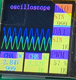
Figure A

Figure B
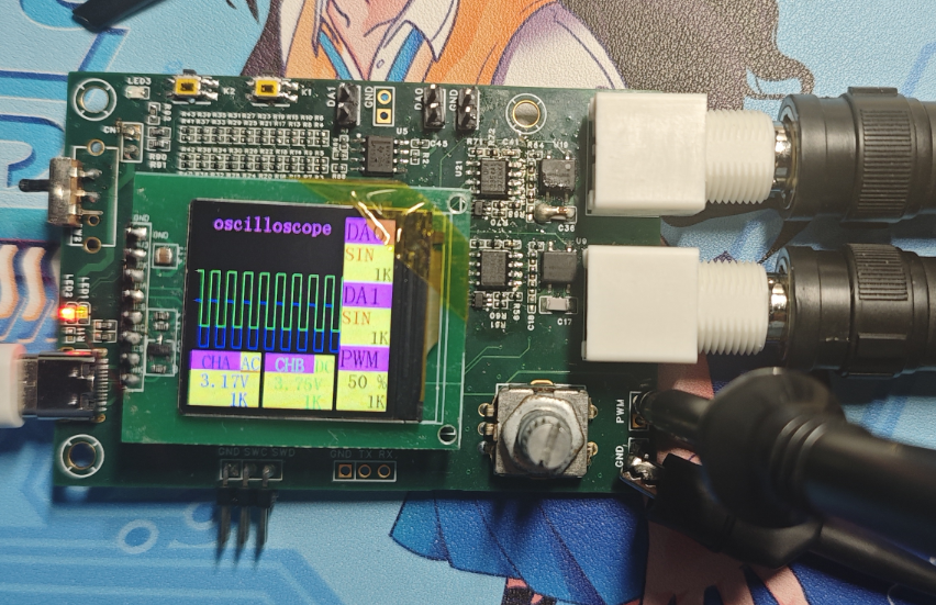
Figure C
2. Lissajous Figure:
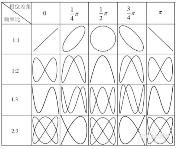
A Lissajous figure, also known as a Lissajous curve or Bodich curve, is the trajectory of the synthesis of two sinusoidal vibrations along mutually perpendicular directions. This graph is generated by applying the measured sinusoidal signal and a standard signal with a known frequency to the Y-axis and x-axis inputs of an oscilloscope, respectively. On the oscilloscope display, the combination of these two signals presents a unique graph, a Lissajous figure, as shown in the image above.
The shape of the Lissajous figure changes depending on the frequency, phase, and amplitude of the two input signals. For example, when the phase difference between the two signals is 90°, the combined graph is an ellipse; if the amplitudes of the two signals are the same, the combined graph is a circle. When the phase difference between the two signals is 0°, the combined graph is a straight line; if the amplitudes of the two signals are the same, this straight line forms a 45° angle with the x-axis, as shown in the image below.
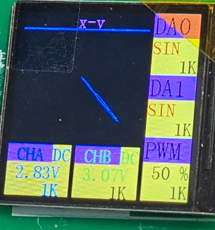
The Lissajous figure of two sinusoidal waves with the same phase and frequency seemed incorrect; the cause was found to be that the origin of the image was drawn at the lower right corner in the program. Mirroring it horizontally corrected the issue.

The Lissajous figure shows a frequency ratio of 1:2.
3. DAC Output Waveform:
Principle: The corresponding values of each waveform sampling point are pre-stored. The DMA transfer frequency is controlled by a timer. The DMA moves the samples from memory (pre-stored sampling points) to the GPIO port without any CPU intervention. The CPU only intervenes once when adjusting the waveform or frequency. Therefore, the phase of the two channel output waveforms will be different each time the waveform is configured. Phase synchronization is also simple; it can be solved by configuring both channels simultaneously or in a very short time.
The GPIO port data corresponding to the sine wave can be output using Python:
# python, sine wave conversion
import math
period = 2*math.pi
point = 128
amp = 418
tup_sin = {i: None for i in range(64)}
print(f"const uint16_t sin_buf[{point}]=")
print("{")
for i in range(point):
if i%10==0:
print()
angle = i*period/point
value = math.sin(angle)
value = int(value*amp)
value = value+amp
tup_sin[i] = int(value)
print("//output sine wave")
print(f"const uint32_t sin_buf[{point}]=")
print("{")
for i in range(point):
if i%10==0:
print()
data = tup_sin[i]&0x3FF | ((~tup_sin[i]&0x3FF)
print(f"0x{data:
print("};")
print("//output sine wave ends") The
corresponding output result is as follows:
const uint32_t sin_buf[128]=
{//output sine wave
0x25d01a2 , 0x24901b6 , 0x23501ca , 0x22001df , 0x20c01f3 , 0x1f80207 , 0x1e4021b , 0x1d1022e , 0x1be0241 , 0x1ab0254 ,
0x1980267 , 0x1870278 , 0x175028a , 0x164029b , 0x15402ab , 0x14502ba , 0x13602c9 , 0x12802d7 , 0x11a02e5 , 0x10e02f1 ,
0x10202fd , 0xf70308 , 0xed0312 , 0xe4031b, 0xdb0324, 0xd4032b, 0xcd0332, 0xc80337, 0xc4033b, 0xc0033f,
0xbe0341, 0xbc0343, 0xbb0344, 0xbc0343 , 0xbe0341 , 0xc0033f , 0xc4033b , 0xc80337 , 0xcd0332 , 0xd4032b ,
0xdb0324 , 0xe4031b , 0xed0312 , 0xf70308 , 0x10202fd, 0x10e02f1 , 0x11a02e5 , 0x12802d7 , 0x13602c9 , 0x14502ba ,
0x15402ab , 0x164029b , 0x175028a , 0x1870278 , 0x1980267 , 0x1ab0254 , 0x1be0241 , 0x1d1022e , 0x1e4021b , 0x1f80207 ,
0x20c01f3 , 0x22001df , 0x23501ca , 0x24901b6 , 0x25d01a2 , 0x271018e , 0x285017a , 0x29a0165 , 0x2ae0151 , 0x2c2013d ,
0x2d60129 , 0x2e90116 , 0x2fc0103 , 0x30f00f0 , 0x32200dd , 0x33300cc , 0x34500ba , 0x35600a9 , 0x3660099 , 0x375008a ,
0x384007b , 0x392006d , 0x3a0005f , 0x3ac0053 , 0x3b80047 , 0x3c3003c , 0x3cd0032, 0x3d60029, 0x3df0020, 0x3e60019,
0x3ed0012, 0x3f2000d, 0x3f60009, 0x3fa0005, 0x3fc0003, 0x3fe0001, 0x3ff0000 , 0x3fe0001 , 0x3fc0003 , 0x3fa0005 ,
0x3f60009 , 0x3f2000d , 0x3ed0012 , 0x3e60019 , 0x3df0020 , 0x3d60029 , 0x3cd0032, 0x3c3003c , 0x3b80047 , 0x3ac0053 ,
0x3a0005f , 0x392006d , 0x384007b , 0x375008a , 0x3660099 , 0x35600a9 , 0x34500ba , 0x33300cc , 0x32200dd , 0x30f00f0 ,
0x2fc0103 , 0x2e90116 , 0x2d60129 , 0x2c2013d , 0x2ae0151 , 0x29a0165 , 0x285017a , 0x271018e 4.


PWM Output:


 京公网安备 11010802033920号

 AT27C512R-15JI


