Background:
In modern society, robots and related technologies are widely used in many fields such as machinery, electronics, transportation, national defense, and agriculture. With the extensive and in-depth development of robot research, robots are no longer limited to manufacturing but have been extended to non-manufacturing fields such as mining, rescue, and hydropower system maintenance, with mobile robots being a prime example. WIFI wireless communication has the advantages of large coverage area and high transmission speed, enabling robots to work in some hazardous environments. Intelligent vehicles, due to their advantages such as automatic tracking, obstacle avoidance, and controllable driving, can meet the requirements of various environments and tasks. Furthermore, their low manufacturing cost and stable operation make them popular in many hazardous operations and industrial settings. China has begun to rapidly focus on the development of the robotics industry, establishing many high-level research and development bases, laying the foundation for innovation in robot development in the new century. The intelligent vehicle uses an STC32G series microcontroller as its control core. It acquires external environmental signals through infrared sensors, is driven by a motor drive module, and uses a camera to collect video information. The design block diagram of the intelligent vehicle mainly includes a power supply module, obstacle avoidance module, automatic tracking module, motor drive module, camera, WIFI module, and microcontroller.
Research Significance:
Through the study of the STC32G tracked vehicle, it can be understood that intelligent vehicles can autonomously complete tasks without human intervention by using sensors to make judgments and analyses in their environment.
Requirements Analysis:
Functional Requirements
: 1. Use the STC32G microcontroller. The STC32G is a common embedded system controller with strong performance and flexibility.
2. Wireless Control: Control the vehicle's forward, backward, and left/right rotation via WIFI.
3. Obstacle Avoidance: Detect objects using ultrasonic waves to achieve obstacle avoidance.
4. Sounding: Achieve sounding by detecting high and low electrical frequencies using an active buzzer. 5.
Distance Measurement and Parking: Achieve parking by measuring distance using the NRF2401 module.
Design Constraints (Hardware, Time Cost, and Economic Cost, etc.) :
Hardware Design Constraints
: 1. Sensor Selection: Select high-precision, low-cost, and high-performance sensors to control the vehicle and for data storage and transmission.
2. Signal Acquisition and Processing: Design suitable circuits to acquire and process the analog signals output by the sensors.
3. MCU Processor Selection: The STC32G12K128 is used as the core. Compared to the 51 microcontroller, the STC32G can accommodate smaller systems and is faster.
4. PCB Layout and Packaging: During hardware design, the layout and packaging must be checked for rationality and correctness.
5. Battery Management: A 12V battery is used for power; the stability and efficiency of the power supply must be ensured.
Time Costs:
1. PCB Design Time: This includes schematic design, package import, and PCB design.
2. PCB Production Time: Orders are placed using JLCPCB, and receiving the order requires a certain amount of time.
Solution Design :
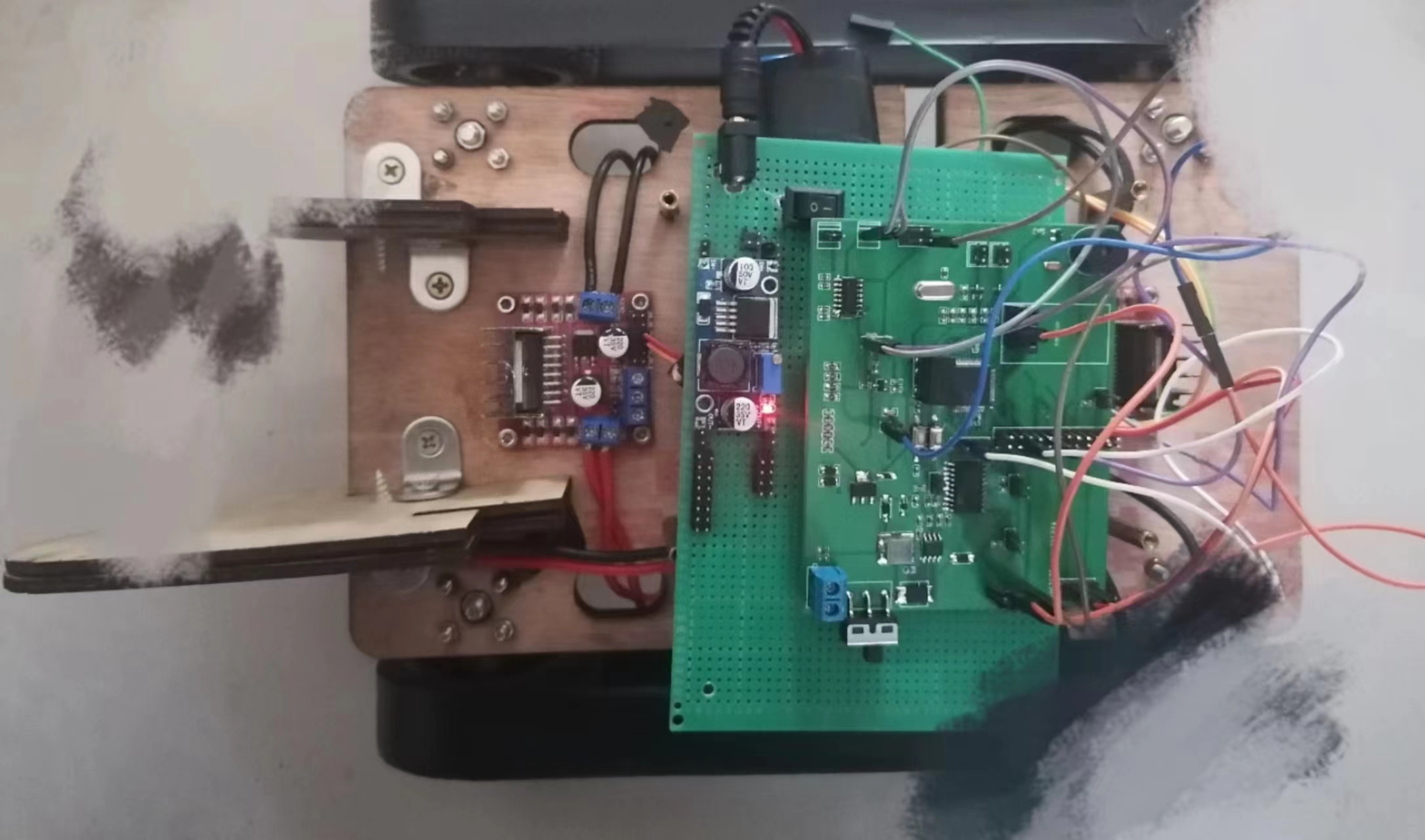
The overall hardware solution design
uses the STC32G12K128 as the core. Compared to the 51 microcontroller, the STC32G can accommodate smaller systems and is faster. The system outputs PWM to control the motor; detects obstacles at a distance of 15cm; uses serial communication for debugging the intelligent car, with the baud rate set to 115200; processes and judges received commands; connects to and controls the WIFI module, enabling the car to move forward, backward, and rotate left and right. For
the motor drive
, to allow the PC to control the car's speed and meet the DC motor's drive voltage requirements, the L293DD motor driver chip is used to power the DC motor.
The motor status and STC32G input are shown in the table. The motor driver has two power input interfaces, one 5V and the other 12V. During use, the 12V interface input voltage must be greater than 7V, while the 5V interface can power the microcontroller
.
The servo
motor has three input lines: the red one in the middle is the power line, and the black one on one side is the ground line. These two lines provide the servo motor with the most basic energy guarantee, mainly for the motor's rotation. There are two power supply specifications: 4.8V and 6.0V, corresponding to different torque standards, i.e., different output torques. The 6.0V supply corresponds to a larger torque, depending on the application conditions. The other wire is the control signal wire; Futaba's is generally white, while JR's is generally orange.
The PWM servo controls
the servo with a 20ms pulse width modulation (PWM) signal. The pulse width ranges from 0.5ms to 2.5ms, corresponding to a linear change in the servo head position from 0 to 180 degrees. In other words, providing a certain pulse width will keep its output shaft at a corresponding angle, regardless of changes in external torque, until a pulse signal of a different width is provided, at which point it will change its output angle to the new corresponding position.
Summary and Outlook
: 1. Ultrasonic obstacle avoidance is not effective. In some cases, obstacle avoidance fails when ultrasonic waves detect objects.
2. WIFI communication sometimes drops. During communication, there are frequent connection failures or inability to receive data, requiring optimization.
3. The appearance needs improvement. Further design improvements are possible.


 京公网安备 11010802033920号

 XPD0250CT-001-C1PFPN


