The LED strip arrangement is as follows.
Note the number of LEDs in each slot. If the number is incorrect, you need to modify the code to match the number of your LEDs; otherwise, there will be display issues.
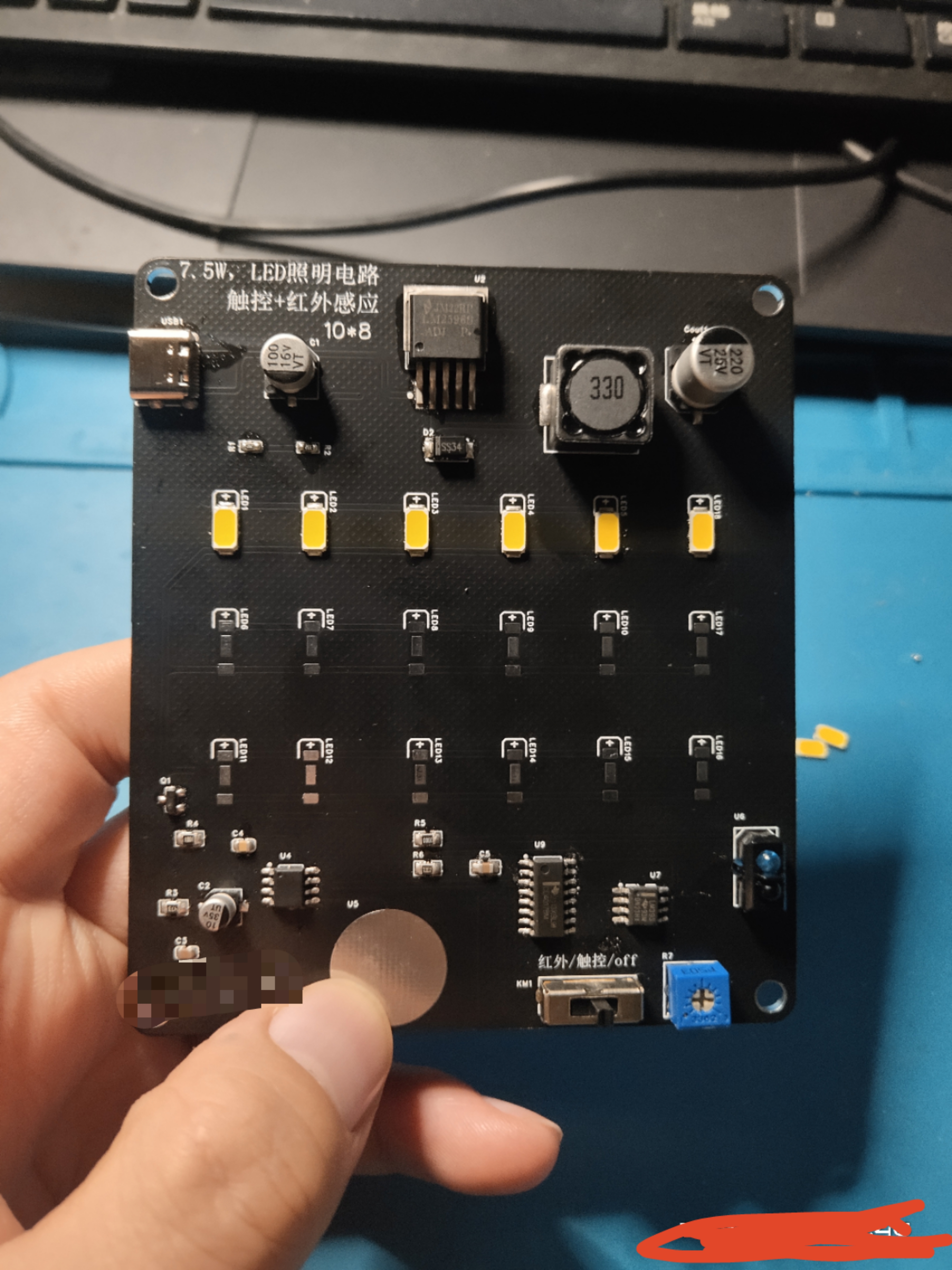
The circuit for a touch-sensitive desk lamp controlled by an 8022W power supply, plus an infrared switch mode.
This product uses 18 LED5730 beads to form a 9W lighting circuit (suitable for dormitory desktop lighting; sufficient brightness; two rows of warm-colored LEDs and one row of cool-colored LEDs can be used for better lighting effect).
1. Power Supply: 5V from Type-C port, 3.3V high-current power from LM2596ADJ;
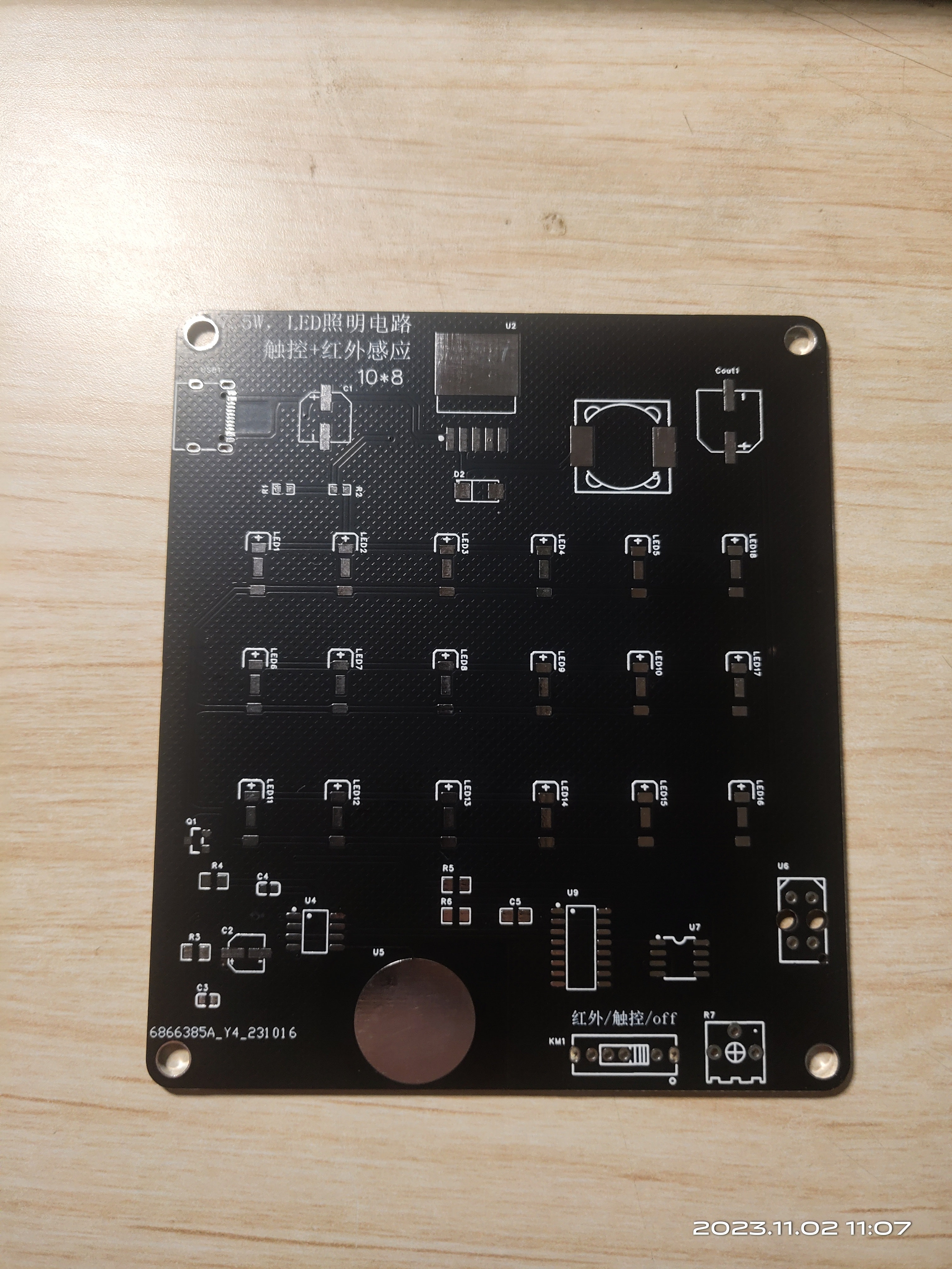
2. Driver: N-channel MOSFET AO3400 drives the LED module;
3. Control: 8022W chip touch control, using mode 3, with memory and stepless dimming mode; the infrared section uses TRCT5000 to sense infrared signals and compare/latch to control LED on/off.
PDF_10W LED Light, Touch + Infrared.zip
Altium_LED_10W, Touch + Infrared.zip
PADS_LED light 10W, touch + infrared.zip
BOM_LED light 10W, touch + infrared.xlsx
96642
SuperCom
This is a 4-channel USB-to-serial adapter board based on SL2.1A and CH343P, with each serial port supporting a maximum communication rate of 6Mbps.
Sometimes, multiple serial ports are needed for debugging. Using multiple USB-to-TTL modules would occupy all the limited USB ports on a computer, and it's also unsightly. Therefore, this small module was created, which supports four 6Mbps serial ports working simultaneously. It supports three common voltage levels: 1.8V, 3.3V, and 5V. Simply short-circuit the appropriate VIN level according to your needs.
PDF_SuperCom.zip
Altium_SuperCom.zip
PADS_SuperCom.zip
BOM_SuperCom.xlsx
96645
TYPE-C debug adapter board
TYPE-C debug adapter board [For internal company use only]
0. PCBA Version
The current description of the compatible version is V01-20231214
. 1. Scope of application:
This project is a TYPE-C debugging adapter board, which is suitable for projects with TYPE-C connectors for debugging. For example, for the 8155 host, S61 FCM project
2. Version Description:
This PCBA has two versions, one for the 8155 host and the other for the S61 FCM project (the pin definitions of the TYPE-C male connectors for the two projects are different); they are not interchangeable. Please pay attention to whether they are applicable to the current project before use.
The method of differentiation is shown in the figure below:
PN1: 0402 package resistors in columns 1 and 3 on the right side of the TYPE-C male connector in the S61 FCM version; the TYPE-
C male connector in the S61 FCM version does not support reversible insertion. PN2: 0402 package resistors in columns 2 and 4 on the right side of the TYPE-C male connector in the 8155 version; the TYPE-C male connector in the 8155 version supports reversible insertion.

3. Function Description:

3.1 USB TYPE-C Male Connector: Used to connect the TYPE-C female connector on the DUT PCBA.
8155 Project Function: Used to connect the TYPE-C female connector on the DUT PCBA, supports reversible insertion.
S61 FCM Project Function: Used to connect the TYPE-C female connector on the DUT PCBA, does not support reversible insertion.
3.2 SW1 Switch:
8155 Project Function:
Switch to upper position -> NA
switch to middle position -> Normal operation
switch to lower position -> USB programming mode.
S61 FCM Project Function (SoC_EMU0):
Switch to upper position -> NA
switch to middle position -> Normal operation
switch to lower position -> Enter JTAG boundary scan mode.
3.3 SW2 Switch:
8155 Project Function: NA.
S61 FCM Project Function (PR0_PRU0_GPO4):
3.4 SW3 Switch:
8155 Project Function: NA.
S61 FCM Project Function (WatchDog_Shield_EN):
Switch to upper position -> Shield WTD watchdog function.
Switch to middle position -> Normal operation
switch to lower position -> NA.
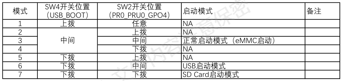
3.5 SW4 Switch:
8155 Project Function: NA.
S61 FCM Project Function (USB_BOOT):
3.6 DC-3_1.27mm_20P Connector:
Connects to J-LINK via a gray ribbon cable, using the JTAG/SWD interface to program the MCU in the DUT.
Gray ribbon cable link: https://item.taobao.com/item.htm?spm=a1z09.2.0.0.17182e8d8Ox6LK&id=743314902167&_u=l1f60ejq4e4f
Gray ribbon cable specifications: 1.27 to 2.54 20P, 200mm
Note: Both ends of the gray ribbon cable have a foolproof design, as shown in the picture below. Pay attention to the orientation when installing the gray ribbon cable, otherwise the MCU software inside the DUT cannot be programmed.
(Image to be added)
3.7 USB TYPE-C Female Connector 1:
8155 Project Function: NA
3.8 USB TYPE-A Female Connector:
8155 Project Function: NA
3.9 USB TYPE-C female connector 2:
This port is the USB interface for the onboard USB to UART module. If the board has an onboard CH343P module, it can be connected to a computer via a USB TYPE-A to TYPE-C data cable (Android TYPE-C data cable) to use a serial communication host computer to communicate with the MCU/SOC inside the DUT.
3.10 UART Voltage Selection Switch:
Level selection for the DUT's onboard MCU/SOC UART port:
Switch in the upper position -> 3.3V;
Switch in the middle position -> 1.8V;
Switch in the lower position -> 5.0V.
UART level selection reference:
8155 Project:
MCU: 3.3V;
SOC: 1.8V;
S61 FCM Project:
MCU: 3.3V
; SOC: 3.3V.
Note: Please select this switch correctly. Incorrect selection will prevent the PC host computer from communicating normally with the MCU/SOC inside the DUT via UART.
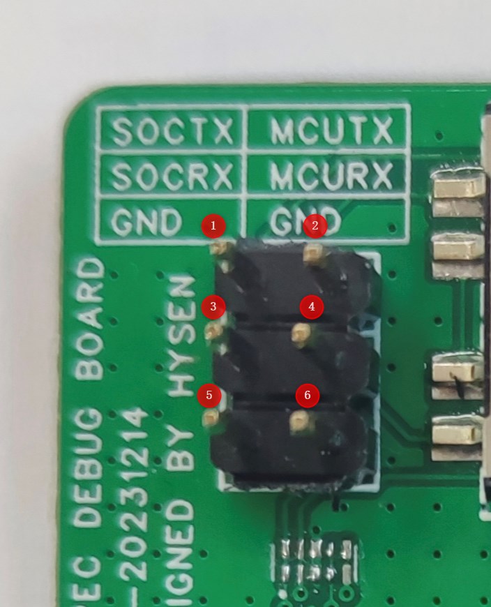
3.11 UART Pin Headers:
Pin 1: DUT SOCTX, needs to be connected to the RX pin of the serial port board . Pin
2: DUT MCUTX, needs to be connected to the RX pin of the serial port board.
Pin 3: DUT... SOCRX, needs to be connected to the TX pin of the serial port board
. Pin 4: DUT MCURX, needs to be connected to the TX pin of the serial
port board. Pin 5: GND, one of pins 5/6 must be connected to the GND of the external USB to UART serial port board; otherwise, the PC host computer cannot communicate normally with the MCU/SOC inside the DUT via UART .
Pin 6: GND, one of pins 5/6 must be connected to the GND of the external USB to UART serial port board; otherwise, the PC host computer cannot communicate normally with the MCU/SOC inside the DUT via UART
. Note: If connecting to the external USB to UART serial port board via UART header pins, the [3.12 UART Channel Selection Switch] must be set to the middle position; otherwise, the PC host computer cannot communicate normally with the MCU/SOC inside the DUT via UART.
3.12 UART Channel Selection Switch:
[3.9 USB...] 【TYPE-C Female Connector 2】When using the onboard CH343P module, this switch is required to select the communication target. With the switch
in the upper position -> SOC, communication with the SOC via the UART interface is selected.
With the switch in the middle position -> OPEN, in the open circuit state, communication with the PC via the external serial port board is achieved through 【3.11 UART header】. With the switch
in the lower position -> MCU, communication with the MCU via the UART interface is selected.
4. Instructions for Use:
4.1 Using this TYPE-C debugging adapter board to program the 8155 MCU
4.1.1 Preparation
①DUT-8155 host
② Host power supply harness
③ Adjustable power supply
④ TYPE-C debug adapter board
⑤ Gray ribbon cable (1.27 to 2.54 20P)
⑥ J-LINK debugger
⑦ J-LINK USB square port harness
⑧ PC
4.1.2 Environment Setup
4.1.3 Programming steps
refer to the corresponding ESW output guide document
(to be updated
) 4.2 Using this TYPE-C debug adapter board to program the 8155 SOC (
to be updated
) 4.3 Using this TYPE-C debug adapter board to program the S61 FCM MCU
(to be updated
) 4.4 Using this TYPE-C debug adapter board to program the S61 FCM SOC
(to be updated
) 4.5 Using this TYPE-C debug adapter board to perform UART communication with the DUT's internal MCU (using the onboard CH343P module - USB to UART) (
to be updated )
4.6 Using this TYPE-C debug adapter board to perform UART communication with the DUT's internal SOC (using the onboard CH343P module - USB to UART)
(to be updated
) 4.7 Use this Type-C debug adapter board to establish UART communication with the DUT's internal MCU (using an external USB to UART serial port board).
(To be updated
4.8) Use this Type-C debug adapter board to establish UART communication with the DUT's internal SOC (using an external USB to UART serial port board).
(To be updated )
PDF_TYPE-C debug adapter board.zip
Altium_TYPE-C debug adapter board.zip
PADS_TYPE-C debug adapter board.zip
BOM_TYPE-C debug adapter board.xlsx
96646
Ordinary electronic keyboard
This electronic keyboard, based on the 51 microcontroller, is simple, practical, and highly entertaining. It is recommended for piano enthusiasts to make one.
I. Research Background
Pianos are increasingly becoming a part of our daily lives, serving as a form of entertainment. However, pianos are relatively expensive, leading to a growing demand for convenient, real-time, and low-cost alternatives. We considered how to manufacture pianos in a more convenient and cost-effective way, and embedded systems, due to their miniaturization, high performance, and low power consumption, became our first choice.
II. Product Introduction
An electronic keyboard is an electronic keyboard instrument, belonging to the category of electronic music synthesizers.
The electronic keyboard was invented to mimic the sound and function of a piano using electronic components. It typically consists of a keyboard, sound generator, amplifier, and controller. An electronic keyboard can produce various sounds, such as piano, guitar, violin, and drums, through a built-in sound library or external sound sources. It can also create different musical effects by adjusting parameters such as timbre, volume, and rhythm.
Electronic keyboards are generally lighter and more portable than traditional pianos and can be powered by batteries or a power adapter. They can also be connected to other electronic instruments or computers to expand their functionality and creative potential.
Electronic keyboards have wide applications in music education, home entertainment, and popular music production. For beginners, the electronic keyboard is a relatively affordable and easy-to-learn instrument choice. For professional musicians, the electronic keyboard can also be used as a tool for creation and performance.
III. Needs Analysis
1. Functional Requirements
① Uses the 51 microcontroller core with an internal real-time operating system.
② Sound amplification: Uses transistors for amplification circuit.
③ Key detection: Uses keys and provides feedback to the user through lights.
④ Sound playback: Uses a buzzer to play sound.
2. Quantitative Technical Indicators
The initial work was mainly to verify the feasibility of the scheme, with low requirements for the algorithm target, only to achieve the function.
① The key will not fail to execute when pressed.
② The diode will not fail to light up when the key is pressed.
③ The buzzer sound is stable.
3. Design Constraints (Hardware, Software, Time Cost, Economic Cost, etc.)
(1) Hardware and software design constraints
(2) The buzzer sound is somewhat different from the real piano tone.
IV. Application Scope
As an electronic keyboard instrument, the electronic keyboard has a variety of functions and features, suitable for the needs of different groups of people. The following are some common electronic keyboard needs analysis:
1. Home entertainment: The electronic keyboard can be used as a way of home entertainment, allowing family members to enjoy the fun of music together. The electronic keyboard's lightweight and portable nature makes it suitable for outdoor or travel use.
2. Composition and Performance: For professional musicians, the electronic keyboard can serve as a tool for composition and performance. By adjusting parameters such as timbre, volume, and rhythm, different musical effects can be created to meet diverse musical composition needs.
3. Children's Toy: For children, the electronic keyboard can be a fun toy that helps develop their musical interests and talents. Electronic keyboards typically offer a rich selection of timbres and rhythms, stimulating children's creativity and imagination.
4. Amateur Music Enthusiasts: For music lovers, the electronic keyboard is a convenient instrument choice, allowing them to practice and play their favorite music at home. Its relatively affordable price also makes music accessible to more people.
In short, the electronic keyboard has multiple functions and features, meeting the needs of different groups. Whether for music education, family entertainment, composition and performance, or as a children's toy or an instrument for amateur music enthusiasts, the electronic keyboard has broad application prospects.
V. Hardware Design
The hardware design
uses a USB Type-C port to connect to the power supply, transistors for amplification circuits, buttons for control, diodes for feedback, and pin headers for programming.
Schematic
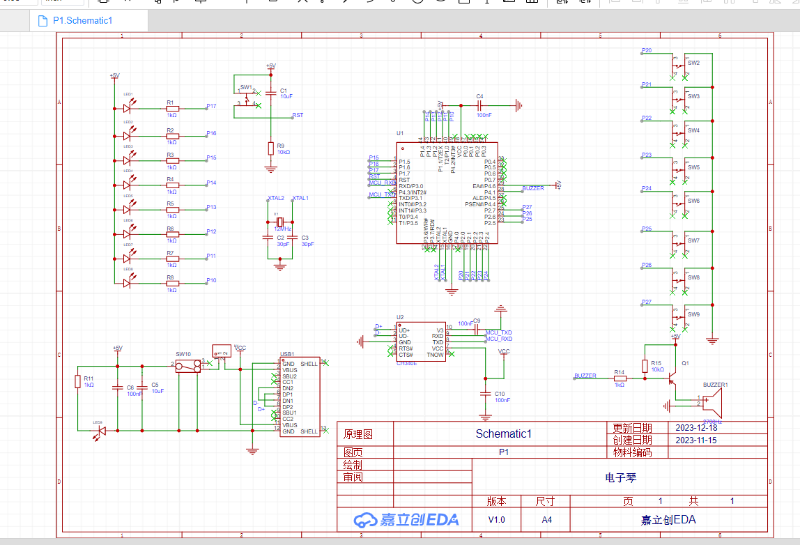
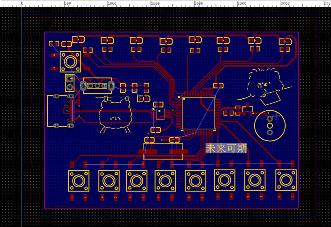
PCB
3D View

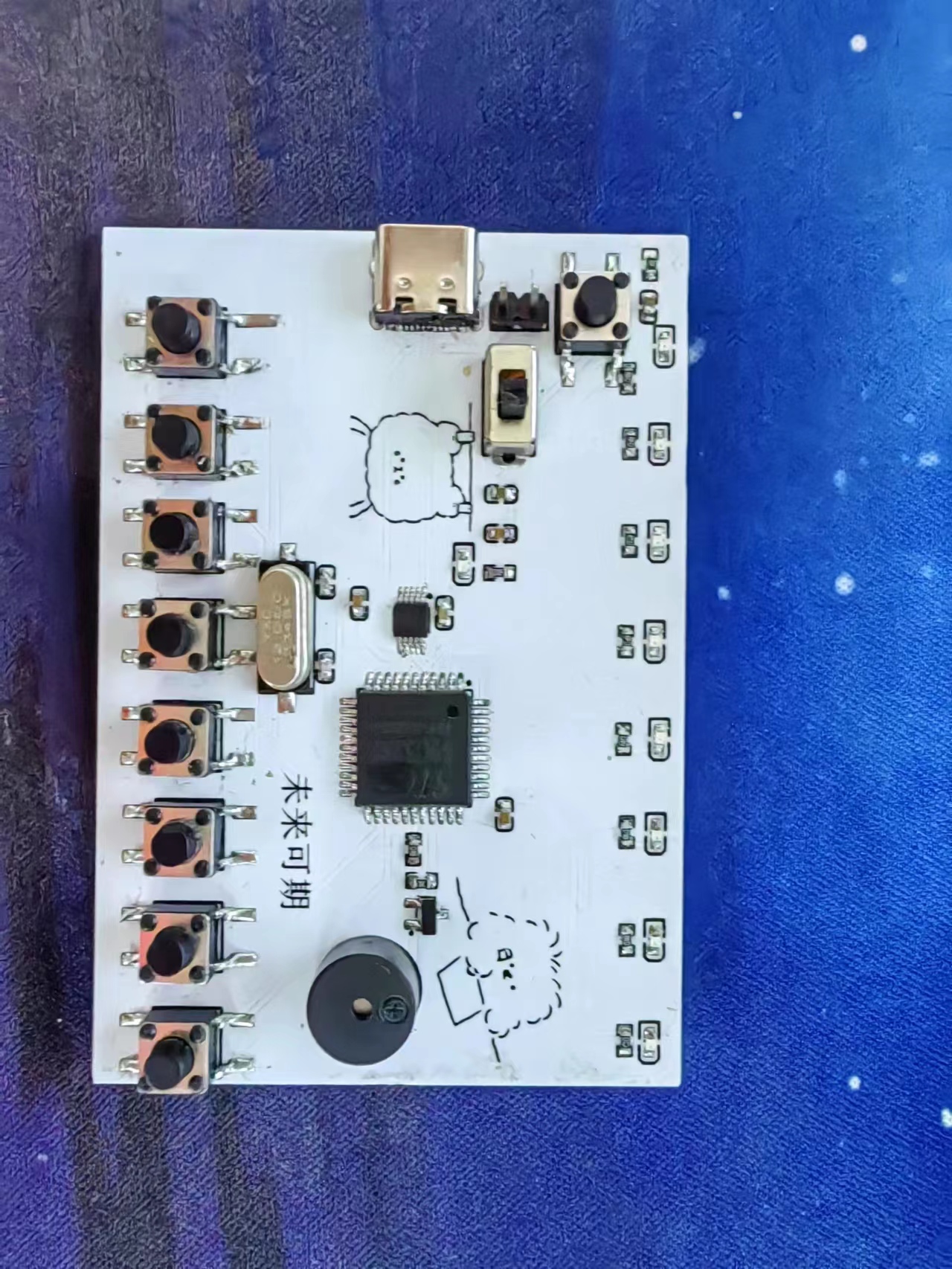
Physical Demonstration
VI. Cost Estimation
The cost of an embedded electronic keyboard is influenced by several factors, including the hardware, software, production scale, and other related factors. Here are some factors that may affect the cost of an embedded electronic keyboard:
1. Hardware Costs: The hardware cost of an embedded electronic keyboard includes the cost of components such as microcontrollers, sensors, keyboards, displays, and audio output devices. Different specifications and performance levels of components will result in different prices.
2. Software Costs: The software costs required to develop an embedded electronic keyboard include programming, debugging, and testing costs. If complex functions or interfaces are required, software costs may increase accordingly.
3. Production Scale: Small-scale production or customized production is generally more expensive.
4. Design and Development Costs: Customized design or development of special functions will increase design and development costs.
Overall, the cost of an embedded electronic keyboard will vary depending on specific needs and specifications. For mass-produced consumer products, costs may be relatively low, while for small-batch production or high-end customized products, costs may be higher.
BOM_Board1_Schematic1_2023-12-22.xlsx
Electronic Keyboard.zip
Screenshot 2023-12-19 213042.png
Screenshot 2023-12-19 210350.png
WeChat image_20231224171326.jpg
PDF_Standard Electronic Keyboard.zip
Altium_Standard Electronic Keyboard.zip
PADS_Standard Electronic Keyboard.zip
BOM_Standard Electronic Keyboard.xlsx
96649
electronic

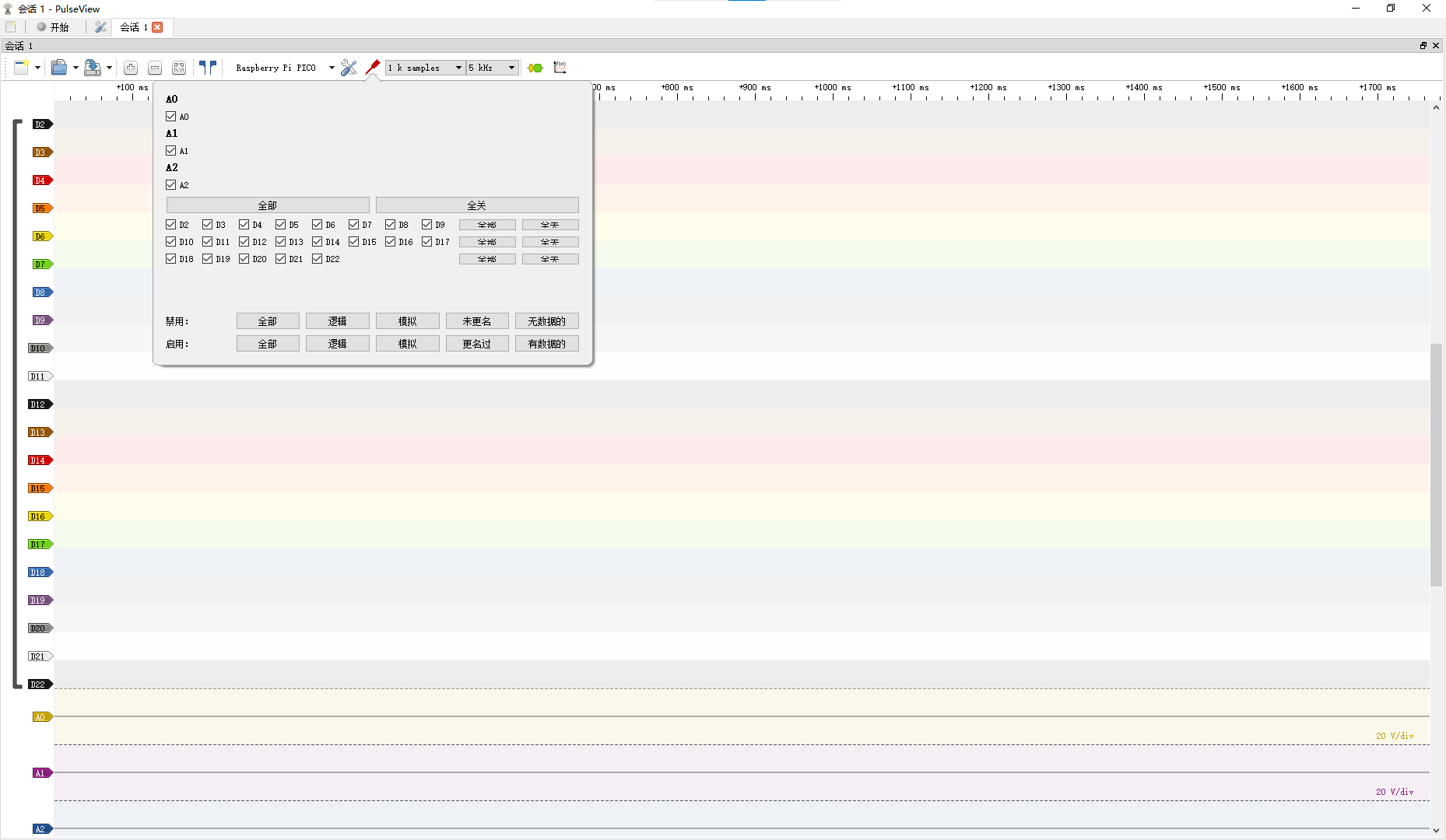
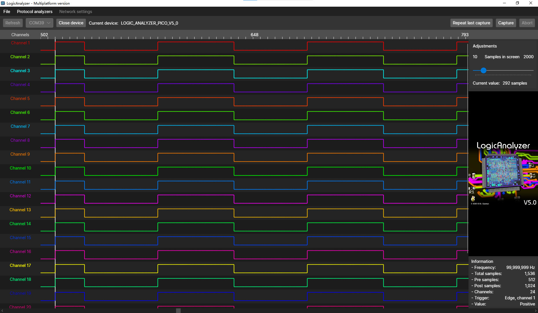 the test used firmware pico_sdk_sigrok.uf2 and supported the PulseView host computer. Channels 22, 23, and 24 can be used as analog channels. The test achieved a very high sampling rate with a 100kHz square wave.


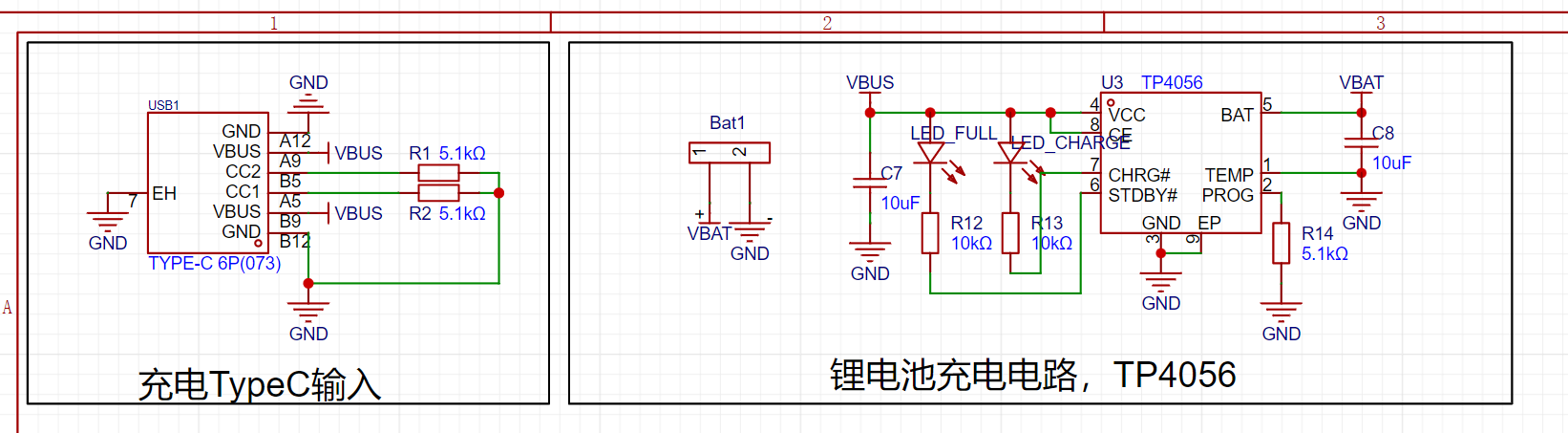 LED_FULL fully charges and lights up; LED_CHARGE charges and lights up.
 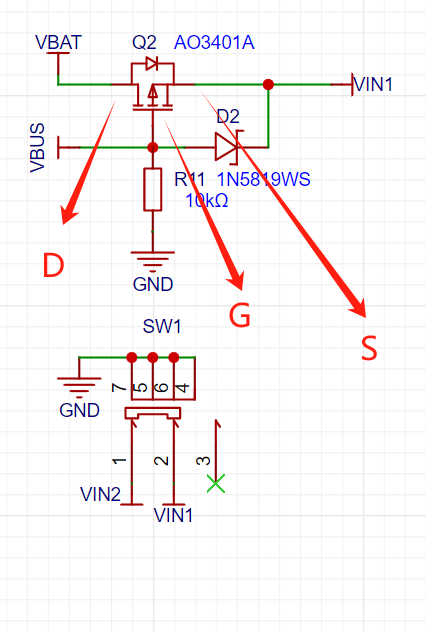 Power supply switching is implemented using PMOS. No Type-C (VBUS = 0), VBAT flows a small voltage to S, then VS > VG, directly SD conducts; powered by lithium battery; with VBUS, the potential at G is higher than S (with Schottky diode), SD does not conduct, VBUS directly supplies VIN1;
  , whether it is 5V or lithium battery voltage input, finally drops to 3.3V output, supplying power to WS2812B and Air001.
 The MCU main schematic
  uses SWD programming method
 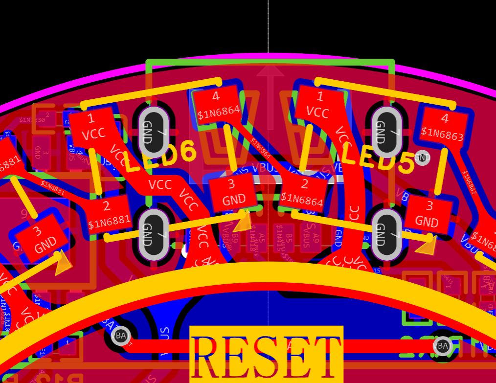 solder Type-C, pay attention to check if the pins are short-circuited, LED5 is generally fine, that GND is interconnected; note that the data pin of LED6 cannot be grounded.
 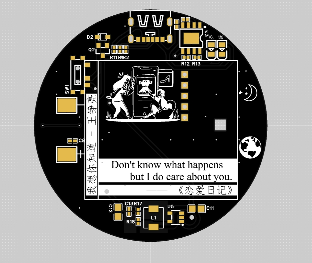 Although I played Wang Daye's song, my favorite is Land Rover!!! (Green)
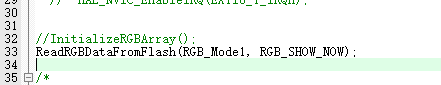
 Two burning steps to save flash data. First burning: uncomment `InitializeRGBArray();`.
  Only monochrome display mode can adjust HSV. Multicolor mode is my custom code written in the flash; you can modify it in the `InitializeRGBArray()` function in `flah.c`. H: 0-360 Hue button; S: 0-1 Saturation button (0 represents white light); V: 0-1 Brightness button (1 is the brightest
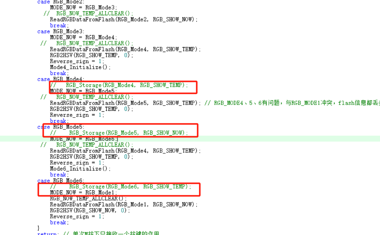
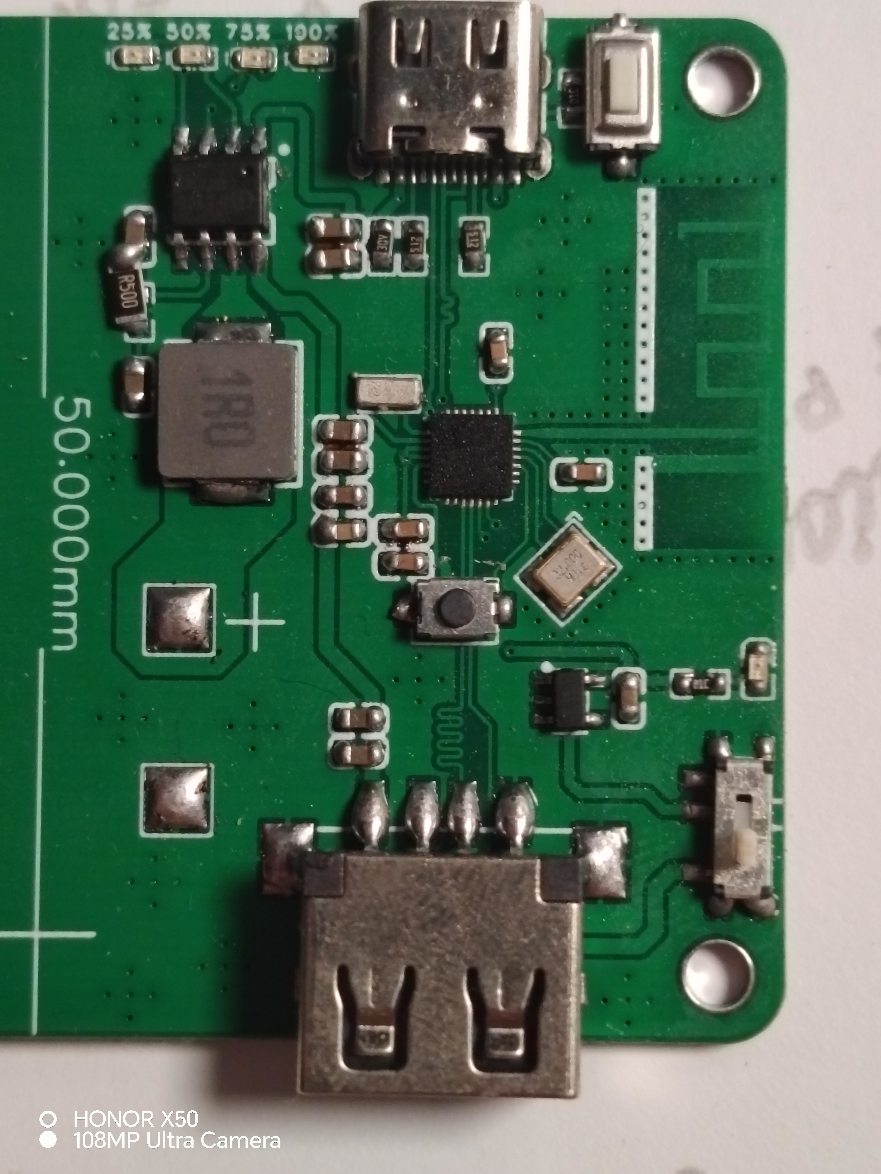 It supports power display (via four LEDs) .
 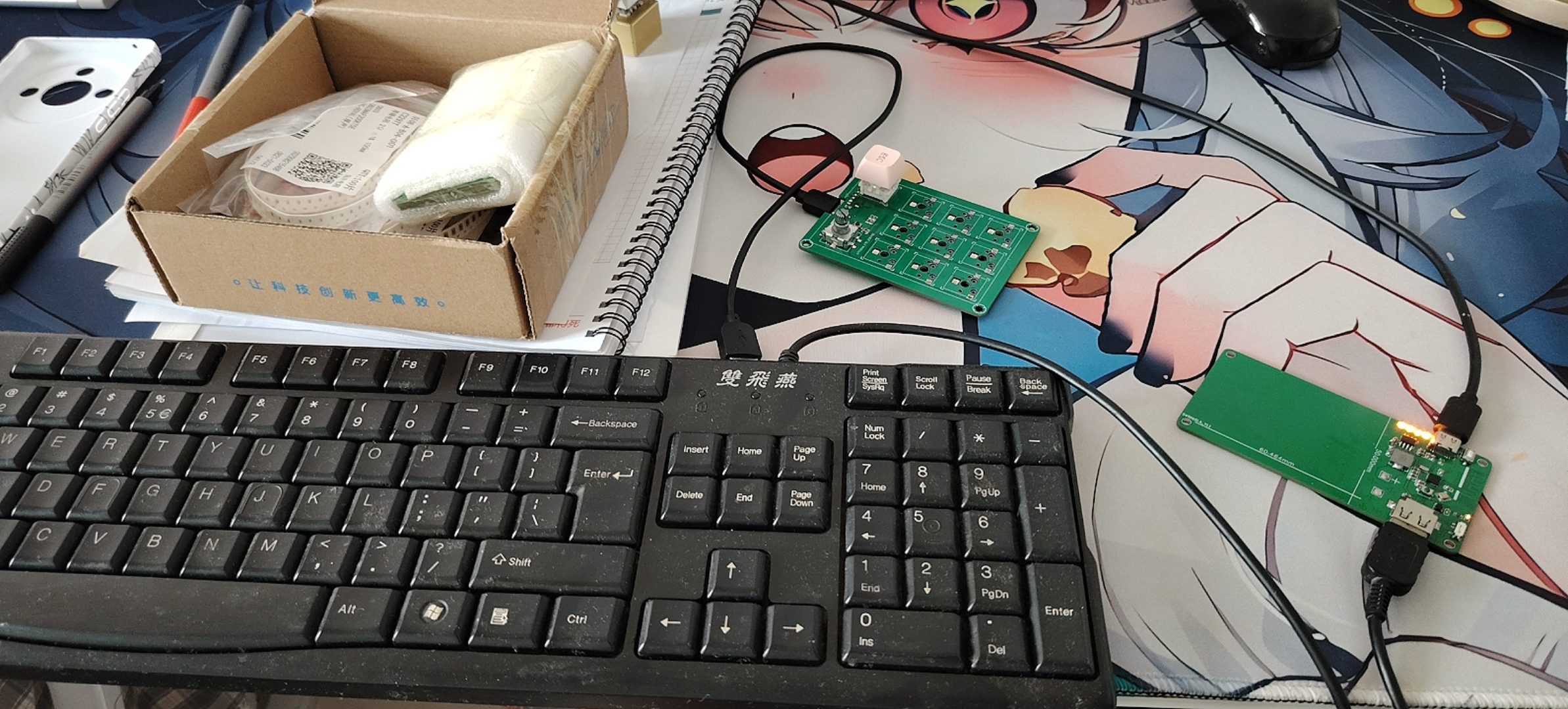 showing that all LEDs can be triggered.
  Currently, this module only supports standard keycodes; some keyboard macros are also supported (see attached video).
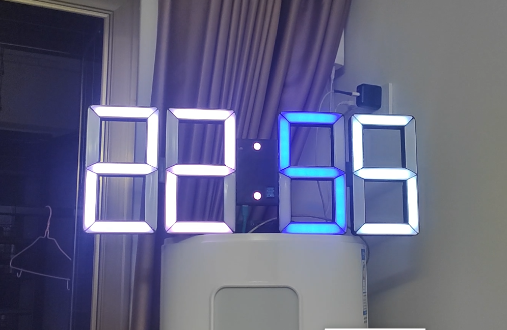
 The LED strip arrangement is as follows.
 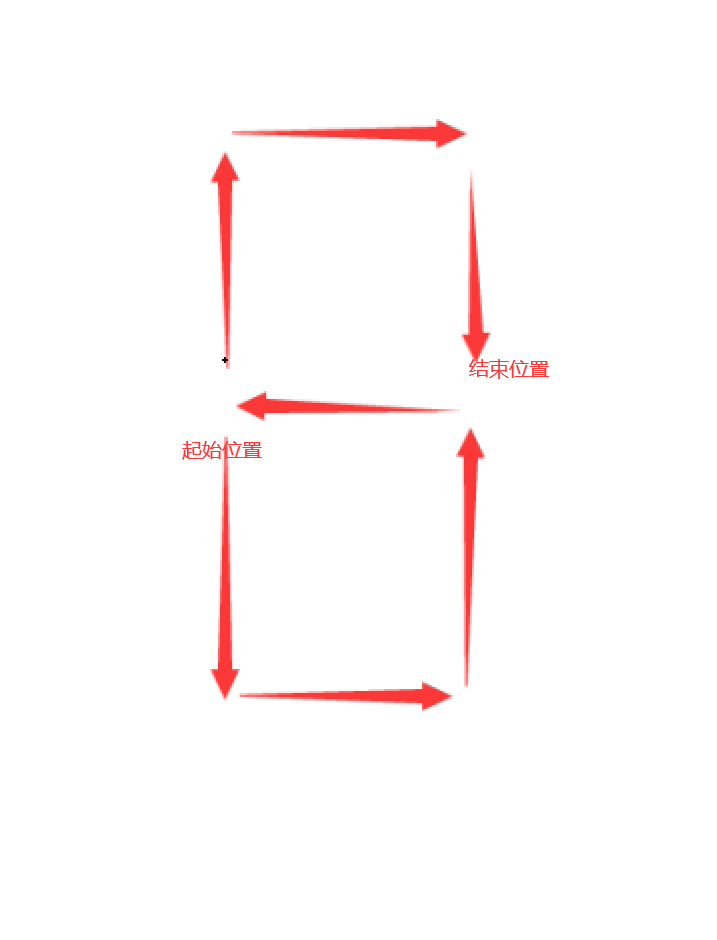 Note the number of LEDs in each slot. If the number is incorrect, you need to modify the code to match the number of your LEDs; otherwise, there will be display issues.
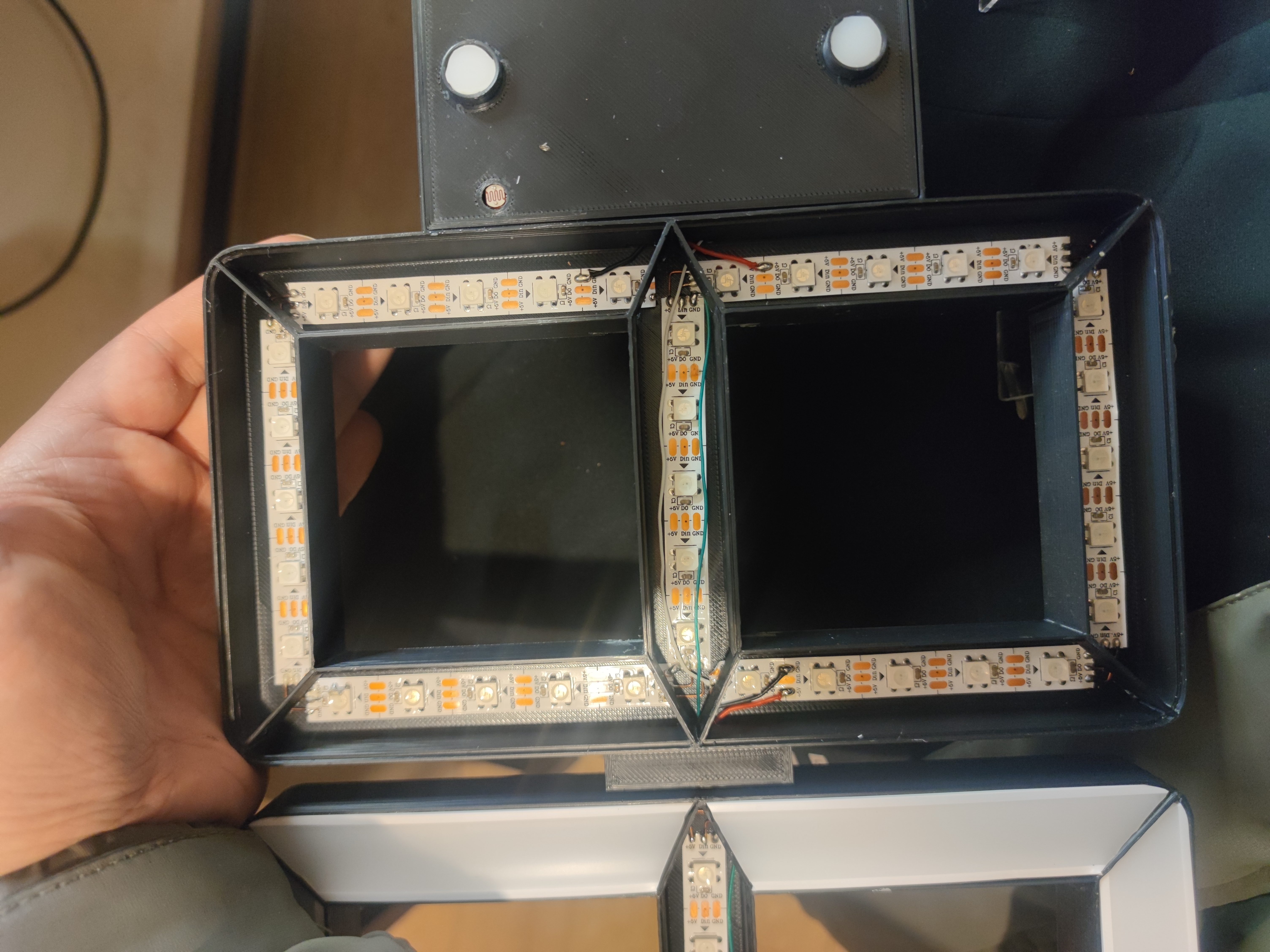


 京公网安备 11010802033920号

 LM3702XCBPX-42


