The PCB version of "The Book of Answers" is a book made using PCB design.
The demo video is still on Bilibili:
https://space.bilibili.com/476762182 .
The source code is attached; it's directly modified from another project, and much of the original project's content hasn't been removed, but it doesn't affect the overall design.

Test_OLED_STM32F103C8.zip
PDF_The Answer Book.zip
Altium_The Book of Answers.zip
PADS_The Book of Answers.zip
96653
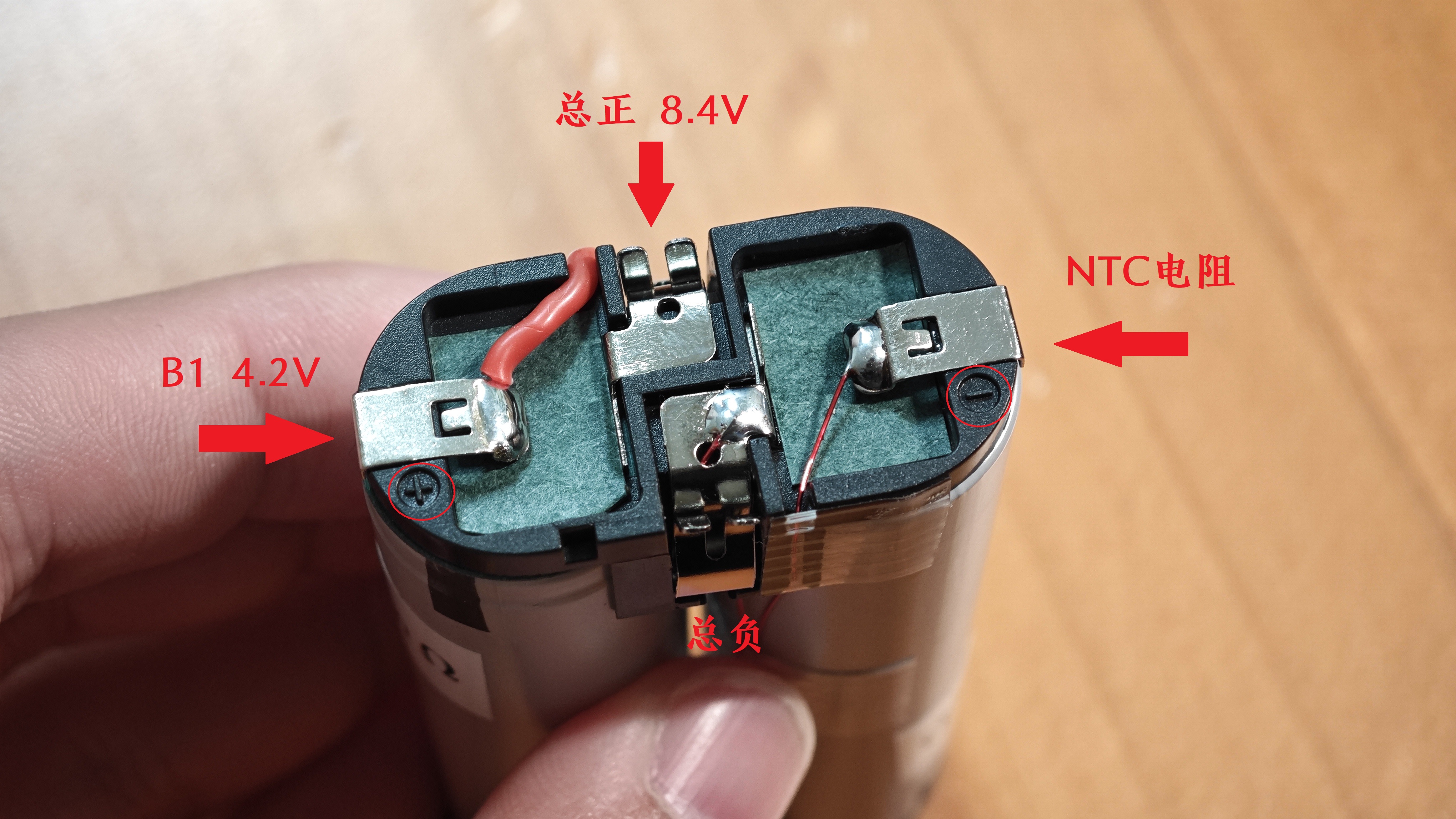
IP2326 charging pad - Makita 7.2V battery pack
The charging board is designed to be used with Makita 7.2V battery packs. It features NTC protection and charging equalization, and parameters can be quickly adjusted via a dial. It is suitable for making simple chargers or for secondary development.
It's not that original batteries are too expensive, but rather that homemade batteries offer better value for money.
1. If the charging board uses NTC and equalization functions, it's only suitable for Makita 012 and 022 homemade battery packs; original batteries won't work.
2. If you don't use NTC and equalization, both homemade and original batteries are acceptable; there are no restrictions.
Many experts have already open-sourced the IP2326 circuit on open-source forums; the projects are directly copied from the official schematics.
Here are some points to note:
1. I've purchased both IP2326 components from LCSC, and both are usable. The information I have only shows that I can't distinguish between IP2326 and IP2326_NPD. If anyone knows, please reply in the comments.
2. The PCB battery spring package has been modified; the inner hole has been changed to 1.0mm for easier and more precise positioning during soldering.
3. The NTC and B+ terminal springs should have a working height of 3.8mm (C5157250).
4. NTC and equalization are not needed. Do not solder either spring. For the NTC, solder a 51K pull-down resistor.
5. The battery kit I bought from Xianyu (a second-hand marketplace) came with an NTC resistor whose parameters I don't know. It's best to replace it with a 100K NTC resistor with a B value of 3950.
6. Do not remove the battery casing cap before testing is complete; it will be difficult to remove once attached.
7. It's best to use a charger with QC protocol. This will allow the chip's negotiated input voltage to gradually rise to around 7V, reducing voltage drop and heat generation. With PD, it only operates at 5V throughout.
8. Whether a homemade battery can be charged with the original charger is unknown. (Most likely not, as I don't have the original charger.)

PDF_IP2326 Charging Board - Makita 7.2V Battery Pack.zip
Altium IP2326 charging board - Makita 7.2V battery pack.zip
PADS IP2326 charging board - Makita 7.2V battery pack.zip
BOM_IP2326 Charging Board - Makita 7.2V Battery Pack.xlsx
96654
Cyber Hourglass - Colored Sand Version (Completely Open Source)
Cyber Hourglass - Colored Sand Version
Cyber Hourglass - Colored Sand Edition: The LED dot matrix has been upgraded to use WS2812 iridescent LED beads, making it incredibly beautiful. The effect isn't great in photos taken with a phone, but it looks fantastic in person.
See the demo video on Bilibili; please follow and like!
[Dao Dao Chu's Personal Space - Bilibili] https://b23.tv/fXla7HD
The microcontroller source code is attached.
The STL file for the casing is attached.
The SolidWorks source file for the casing is attached.
ShaLou7Color.zip
Part 16-1.STL
Part 16-2.STL
Part 16-1.SLDPRT
Part 16-2.SLDPRT
ShaLou.hex
PDF_Cyber Hourglass - Colored Sand Version (Completely Open Source).zip
Altium_Cyber Hourglass-Colored Sand Version (Completely Open Source).zip
PADS_Cyber Hourglass - Colored Sand Version (Completely Open Source).zip
96657
xl2596_3
Three 2596 converters handle adj, 12V, and 5V respectively, while one 1117 converter handles 5V to 3.3V conversion. The 2596 converters performed normally in the tests.
This module is designed for use with 12V, 5V, and 3.3V voltages, and also includes an adjustable voltage channel that allows for voltage adjustment by soldering resistors of different values.
PDF_xl2596_3.zip
Altium_xl2596_3.zip
PADS_xl2596_3.zip
BOM_xl2596_3.xlsx
96658
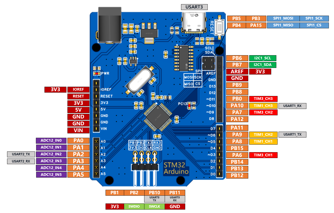
An Arduino development board with an STM32 microcontroller
This is an Arduino development board based on the STM32F103C8T6, with pins fully compatible with Arduino.
To use SimpleFOC on an STM32 microcontroller and with the SimpleFOC Arduino driver board, the idea arose to create an STM32_Arduino circuit board.
An STM32F103C8T6 was used as the main controller, and its shape was drawn exactly according to the Arduino form factor.
Most of the STM32's pins were brought out, achieving pin-to-pin compatibility. The special PWM pins were also dedicated to the STM32 timer output pins.
The pinout diagram is shown below.
A Keil test program project is provided in the attachment, which can be downloaded via STlink.
Program behavior: The LED toggles every 500ms, while simultaneously outputting an incrementing number (0~255) via serial port.
f103c8t6_arduino_test.zip
Altium_An Arduino Development Board with an STM32 Controller.zip
PADS_An Arduino Development Board with an STM32 Microcontroller.zip
BOM_An Arduino development board with an STM32 main controller.xlsx
96659
Type 86 five-hole socket (magnetic latching relay, metering, Zigbee)
The Zigbee intelligent 86-type five-hole wall socket uses a CC2530 magnetic relay and an HLW8032 metering chip.
Type 86 five-hole wall socket, Zigbee (CC2530), power detection, magnetic relay.

PDF_86 Type Five-Hole Socket (Magnetic Latching Relay, Metering, Zigbee).zip
Altium_86 type five-hole socket (magnetic latching relay, metering, Zigbee).zip
PADS_86 type five-hole socket (magnetic latching relay, metering, Zigbee).
96660
Eight-route patrol grayscale 1.2
Using the LM324DR2G chip and ITR20001 infrared sensor module, I created an eight-channel line-following grayscale sensor, an improvement on the previous version, by changing the sensor type. With the support of JLCPCB consumables, I successfully completed the project and it now functions correctly.
This module is primarily used in photoelectric vehicle competitions that require infrared module line following. It is recommended to use supplemental lighting under the vehicle for enhanced sensitivity. Additionally, adding a tantalum capacitor and a 100nF capacitor to the schematic can reduce interference.
video_20231224_155702.mp4
PDF_Eight-Road Patrol Grayscale 1.2.zip
Altium_Eight-Way Line Patrol Grayscale 1.2.zip
PADS_Eight-Road Line Patrol Grayscale 1.2.zip
BOM_Eight-way Line Patrol Grayscale 1.2.xlsx
96661
electronic


 京公网安备 11010802033920号

 AAT351XIGV-4.20AB


