I saw Qinheng's cheap RISC-V microcontroller CH32V003 in a group chat before. It only costs 70 cents per chip. I had been using ESP32 before and was eager to learn about this kind of cheap single-use microcontroller. So I used it to make an ammeter to practice.
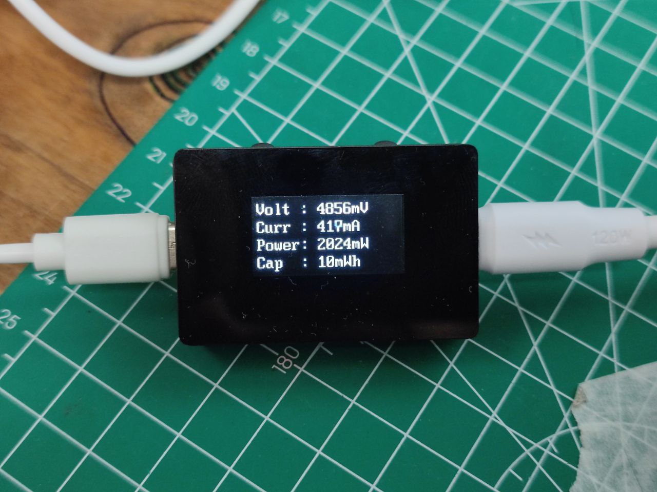
Voltage, Current, Power, and Capacity Interface:
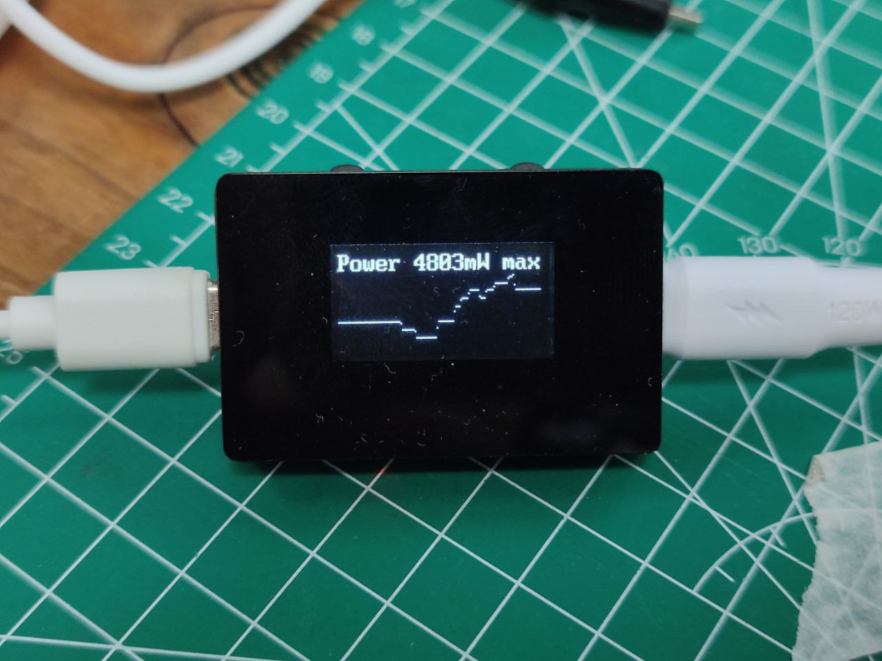
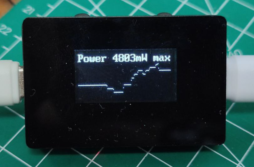
Power History Chart Interface:
USB Ammeter Requirements
Due to limited resources on the CH32V003, not many functions were designed. It is mainly used to verify the capabilities of this MCU and familiarize users with the SDK. Therefore, the main functions of the ammeter are as follows:
USB Type-C input and output;
PD protocol pass-through
support; 5-20V voltage detection
support; 0-5A current detection
support; power calculation and capacity statistics
support; power history chart display
support; statistical data recording and clearing;
button switching between voltage/current data and power history charts;
using INA219 to collect voltage and current related data;
using a 12864 OLED to display related data.
CH32V003 Introduction
The CH32V003 series is an industrial-grade general-purpose microcontroller based on the Qingke RISC-V2A core, supporting a 48MHz system clock frequency, and featuring wide voltage range, single-wire debugging, low power consumption, and ultra-small package. The CH32V003 series integrates a DMA controller, a 10-bit analog-to-digital converter (ADC), an operational amplifier comparator, multiple timers, and standard communication interfaces such as USART, IIC, and SPI.
Official website: https://www.wch.cn/products/CH32V003.html
Main parameters:
32-bit RISC-V2A processor, supports 2-level interrupt nesting,
maximum system frequency of 48MHz
, 2KB SRAM, 16KB Flash,
power supply voltage: 3.3/5V,
multiple low-power modes: sleep, standby, power-
on/power-off reset, programmable voltage monitor,
1 set of 1-channel general-purpose DMA controller,
1 set of op-amp comparators,
1 set of 10-bit ADC
, 1 16-bit advanced timer and 1 16-bit general-purpose timer
, 2 watchdog timers and 1 32-bit system time base timer
, 1 USART interface, 1 set of IIC interface, 1 set of SPI interface,
18 I/O ports, mapping one external interrupt,
64-bit unique chip ID,
serial single-wire debug interface.
Package types: TSSOP20, QFN20, SOP16, SOP8.
For this project, using the 12864 OLED and INA219 requires an I2C interface, while the buttons need to use ordinary GPIO and UART. For debugging information output, SDIO is used for programming. After comparison, the CH32V003F4P6 in TSSOP20 package is more suitable. It has more GPIOs than the CH32V003J4M6 in SOP8 package, and the UART and SDIO are not multiplexed, which better meets the needs of this project.
The MCU

section is straightforward, powered by 3.3V with a 100nF decoupling capacitor. Note that when using I2C with the CH32V003, pull-up resistors need to be added to SCL and SDA.
Although a network identifier is added to the SPI interface, it is not actually used. For
USB Type-C input/output,

to keep the ammeter compact, a USB Type-A interface is not added; both input and output use USB Type-C 16-pin connectors. To avoid affecting PD protocol negotiation, the CC1 and CC2 pins of the input/output are directly connected. Although the other pins have no practical use in the PD protocol, they are all directly connected for compatibility.
There are two points to note regarding this usage: First,
because CC1 and CC2 are not connected to 5.1K pull-down resistors, when using the CC cable and PD charging adapter, the adapter cannot negotiate the PD protocol, therefore it will not supply power, and the ammeter will not start. Second,
because CC1 and CC2 are directly connected without a MUX chip, reversing the charging cable connection will also prevent PD protocol negotiation. Third,
since the USB Type-C connectors on both sides are straight-through, there is no distinction between input and output; either side can be connected to the charger. For
DC-DC power supply
, since the ammeter itself does not have an external power supply, it needs to draw power from the voltage being measured. Since the voltage being measured is relatively high (up to 20V in the PD protocol), a high-voltage power supply solution is required.
The traditional AMS1117 chip does not support a 20V withstand voltage, so a better solution is to use a DC-DC converter. After searching on LCSC, the LGS5145 was chosen. This DC-DC chip has an input voltage range of 4.5V to 55V, which is sufficient to handle the high voltage step-down requirements of PD.

The schematic diagram is drawn directly from the LGS5145 datasheet. R6 and R7 are because I had resistors of those specifications on hand; in actual use, a 30K resistor can be used instead. C6 is a feedforward compensation capacitor and does not need to be soldered. For
voltage and
current measurement, the Texas Instruments INA219 is used. It was chosen because I have used it before and am familiar with it, and there is a readily available library available.
The INA219 is a shunt and power meter with an I2C or SMBUS compatible interface. This device monitors the shunt voltage drop and bus power supply voltage; the number of transitions and filtering options can be set through programming.
The INA219 has a maximum voltage range of 26V. For PD2.0 100W, a maximum of 20V is sufficient. However, it will exceed the range when using PD3.1 140W with a 28V power supply. Currently, there are relatively few chargers and devices supporting 140W, so this issue is not a major concern. The INA226, with its higher range, can be considered as a replacement in the future.
To measure relatively high voltages and avoid excessive heat, a 10mR sampling resistor is used. This results in a power consumption of only 0.25W even at 100W 20V 5A, and in actual testing, it did not overheat during prolonged 100W operation.

The ammeter

uses a common 0.96-inch 12864 OLED screen as its display device. This screen is easy to operate and consumes relatively little power, making it suitable for this scenario. In addition, since a 0.96 OLED bare screen requires relatively complex supporting circuitry, in order to simplify the manufacturing process, a pre-made screen module is directly used and soldered onto the PCB via pin headers.
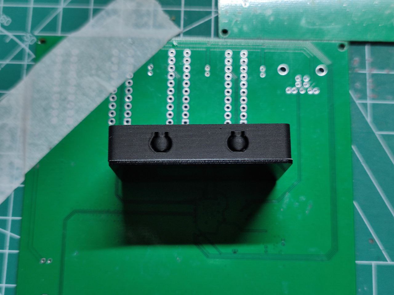
The 2.54mm pin header height allows for a proper distance between the screen and the PCB without pressing on the MCU or other components. Note that U8 and H2 share the same interface; U8 is placed primarily for positioning and alignment.
The buttons are standard side-pressed and triggered by a low level.
For downloading and debugging
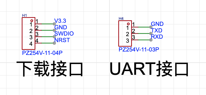
, the CH32V003 series requires a WCH Link-E programmer. In practice, only V3.3, GND, and SWDIO need to be connected to program. If the ammeter's Type-C input has power, only GND and SWDIO need to be connected for programming.
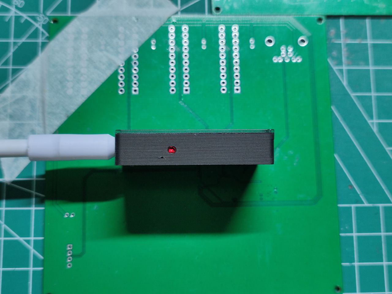
The casing and panel
are 3D printed, with a hole at the bottom to reveal the power status and two buttons on the top for operating the ammeter.
The ammeter panel uses LCSC's custom panel service, directly attached to the casing with adhesive. It must be said that with LCSC's custom panel service, DIY products are becoming increasingly professional.

The ammeter
program is a loop that reads voltage and current, calculates power and capacity, and displays the results.
The I2C and 12864 OLED driver code references the implementation at https://github.com/wagiminator/CH32V003-GameConsole.
Actual testing showed a screen refresh rate of approximately 40 FPS, meaning voltage and current were sampled 40 times per second.
The power history curve is displayed using the average value per minute, with 128 points horizontally, allowing for a total of 128 minutes of power history, which should meet most needs in general scenarios.
In conclusion,
this ammeter is relatively simple overall. The CH32V003 didn't present many problems during use. The main issues encountered were a significant resource shortage compared to the ESP32 and the lack of hardware floating-point calculations. Therefore, in the actual coding process, mV and mA were used as units, and integer calculations were performed.
Furthermore, the DC-DC circuit was the component with the most components in the entire solution. Future plans include replacing it with a high-voltage LDO, such as the HT7533, which can handle input voltages up to 30V. This would simplify the circuit, and since the overall power consumption of the MCU + OLED is only a few milliamps, there shouldn't be any serious heat generation issues.


 京公网安备 11010802033920号

 NRSG561M16V16X25TRF


