For the demonstration video, please click here.
Due to limited expertise, the entire PCB is assembled from modules: a 1S battery is used as the power unit, a 5V boost module powers the microcontroller, a 12V boost module powers the brushless motor, an MPU6050 is used for pose detection, and an LGT8F32P microcontroller control unit (compatible with Arduino Nano).
It uses a small board from Allwinner's F1C100S/F1C200S, featuring onboard ESP8266/8089 wireless networking, CP2102 serial communication, a USB interface, a 0.42-inch OLED screen, and an SPI interface...
This is a small Linux board I designed as a practice project. It uses an F1C100S as the main controller and can run the official firmware for the Lychee Pi series. You can also compile and create your own image file as needed
. It has a variety of peripherals (approximately), including audio input and output, a mini screen on the front, and the back can be configured with different screen sizes (requires driver modifications in the kernel). The board is very small and looks quite refined.
CPU: Allwinner F1C100S / F1C200S;
Serial Port: CP2102;
WIFI: ESP8266 / The ESP8089
resistor-capacitor package is basically 0402, with a relatively high density, requiring considerable hands-on skill .
The TF card slot is quite low, so be careful not to bend the card forcefully when inserting or removing it, otherwise it may be easily damaged . The power supply
uses the EA3036 solution .
>>> ...
PADS_ConcoPi - A small terminal based on F1C100S.
A simple line-following and obstacle-avoiding vehicle was constructed using an LM393 and a 74HC00N paired with an infrared beam transistor, facilitating the understanding of more circuit concepts.
1. Design Requirements
: Design a simple line-following and obstacle-avoiding vehicle. The line-following function should be implemented using digital circuitry, and the obstacle-avoiding function should be implemented using analog circuitry.
2. Overall Design Scheme
: Based on the design requirements, a 74HC00N NAND gate paired with an infrared photodiode is used. The receiver tube is activated by determining whether infrared light is detected, and the signal is input to the NAND gate to achieve digital line-following.
Similarly, an LM393 comparator paired with an infrared photodiode is used. The receiver tube is activated by determining whether infrared light is detected ahead, and the two sets of signals are compared to achieve the obstacle-avoiding function of the analog circuit.
3. Circuit Composition:
3.1 Power Supply Circuit
: Powered by two AA batteries, each with 1.5V, the two batteries connected in series provide 3V, meeting the minimum power requirements of the chip. A three-position sliding switch switches between line-following and obstacle-avoiding functions. Capacitors C1 and C3 are filter and energy storage capacitors. When the motor starts working, the transient current is large, and the 100uF capacitors assist the battery in discharging.
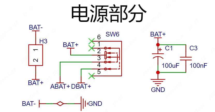
Figure 1 Power Supply Circuit
3.2 Motor Drive Circuit
The positive terminal of the battery is connected to the positive terminal of the motor, and the negative terminal is controlled by a transistor. When a digital tracking or analog obstacle avoidance signal is generated, the base of the transistor is controlled to control the operation of the left and right tires, thereby realizing the tracking and obstacle avoidance functions.
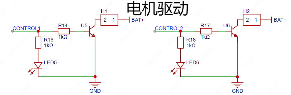
Figure 2 Motor Drive Circuit
3.3 Digital Signal Tracking
U2 and U3 are infrared emitting tubes, and LED3 and LED4 are infrared receiving tubes corresponding to them, which are installed on both sides of the front wheels of the vehicle. The principle analysis is as follows:
1. When the vehicle starts moving and encounters the white paper, the infrared light is reflected and received by the receiver tube, which then conducts. When it encounters the black line, the infrared light is absorbed, and the receiver tube is cut off.
2. The 74HC00N is a NAND gate. When it encounters the black line, the receiver tube is cut off, CNT1 outputs a high level, corresponding to OUT1 outputting a low level and OUT3 outputting a high level.
3. At this time, the high level output by OUT3 flows through the motor transistor, controlling the three stages to conduct, and the motor rotates.
The vehicle continuously encounters black and white lines on the map route, thus continuously turning the transistors on and off, realizing the function of following the track around the black line.

Figure 3 Digital signal tracking circuit
3.4 Analog signal obstacle avoidance
IR1 and IR2 are infrared emitting tubes, and CGQ1 and CGQ2 are the corresponding infrared receiving tubes, installed on both sides of the front of the vehicle. The schematic diagram is analyzed as follows:
1. When the vehicle is running and there is no obstacle in front, the infrared signal will not be received, the receiving tube is cut off, the non-inverting input of the 393 comparator is the battery voltage, the voltage is greater than the inverting input, at this time, the 393 comparator outputs a high level, controlling the vehicle to move forward.
2. When there is an obstacle in front of the vehicle, the infrared signal is received by the receiving tube, the receiving tube is turned on, the non-inverting input of the 393 comparator is low, the voltage is less than the inverting input, at this time, the 393 comparator outputs a low level, the corresponding wheel stops running, thus achieving steering.
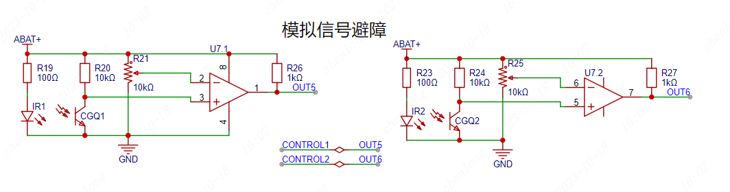
Figure 4 Analog signal tracking circuit
4 PCB design
After completing the schematic design, first check whether the circuit is connected correctly and whether there are any missing or disconnected networks. After all checks are correct, click Design - Schematic to PCB in the top menu bar of the schematic diagram to start the PCB design.
4.1 Appearance design
After generating the PCB, a PCB appearance needs to be set. The size of the appearance needs to be designed according to the number and size of the components and the shell. Adhering to the principle of appropriate size and aesthetics, when designing the appearance of this project, the position of the motor and tires needs to be considered to ensure that the tires and the PCB board will not interfere.
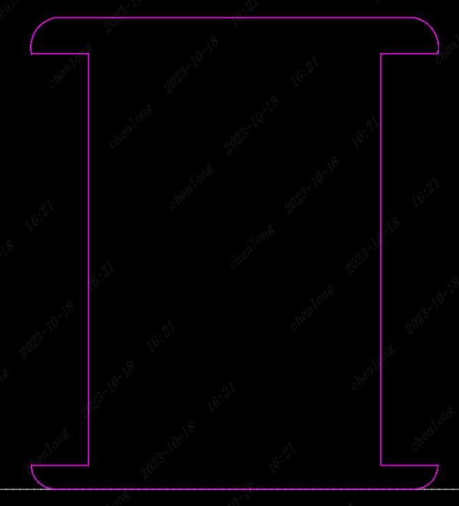
Figure 6. Outline of the Line-Following Cart
4.2 Component Layout
After transferring the components from the schematic diagram to the PCB, the component layout becomes quite messy. The second step in PCB design is to classify and lay out the components. Classification is based on placing components of different circuits together. Using the layout transfer function provided by JLCPCB EDA, each circuit module can be quickly laid out. Note that the infrared photodiode should be placed at the edge of the board to reduce unnecessary interference.

Figure 7. Line-Following Cart Layout
4.3 PCB Routing
When designing a double-layer circuit board, PCB routing is divided into top-layer routing and bottom-layer routing. The top-layer routing is red by default, and the bottom-layer is blue. Routing involves connecting copper wires in the circuit board. Select the layer in the Layers & Elements section, and then connect the pads of two identical nets. Even seemingly simple connections require constant adjustment and optimization. The placement of components also affects the difficulty of routing. Considering the routing more during layout will make it much simpler. Here are some suggestions for routing:
(1) Set power lines to 40mil and signal lines to 10mil;
(2) Prioritize routing on the top layer. Only consider routing on the bottom layer if the top layer cannot be connected smoothly;
(3) Do not route GND. Simply cover the bottom layer with copper;
(4) Prioritize straight lines during routing. Use obtuse angles or rounded bends where necessary;
(5) After completing the routing, add appropriate silkscreen markings to indicate the purpose and interface functions of the PCB board.
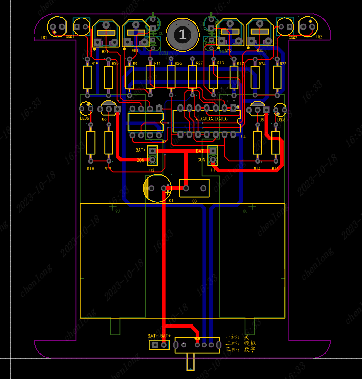
Figure 8. Top-level wiring diagram of the line-following trolley.

Figure 10. Bottom-level wiring diagram of the line-following trolley.
5. Debugging Notes:
1. After soldering, do not insert the battery immediately. First, use a multimeter in continuity mode to test for short circuits.
2. If the vehicle fails to achieve its intended purpose, adjust the value of the adjustable resistor to change the sensitivity.
3. You can use a multimeter to test each input voltage value to more clearly understand the corresponding voltage changes.
4. When purchasing the chip, ensure that the 3V battery meets the chip's minimum operating voltage. If not, try using three batteries connected in series.
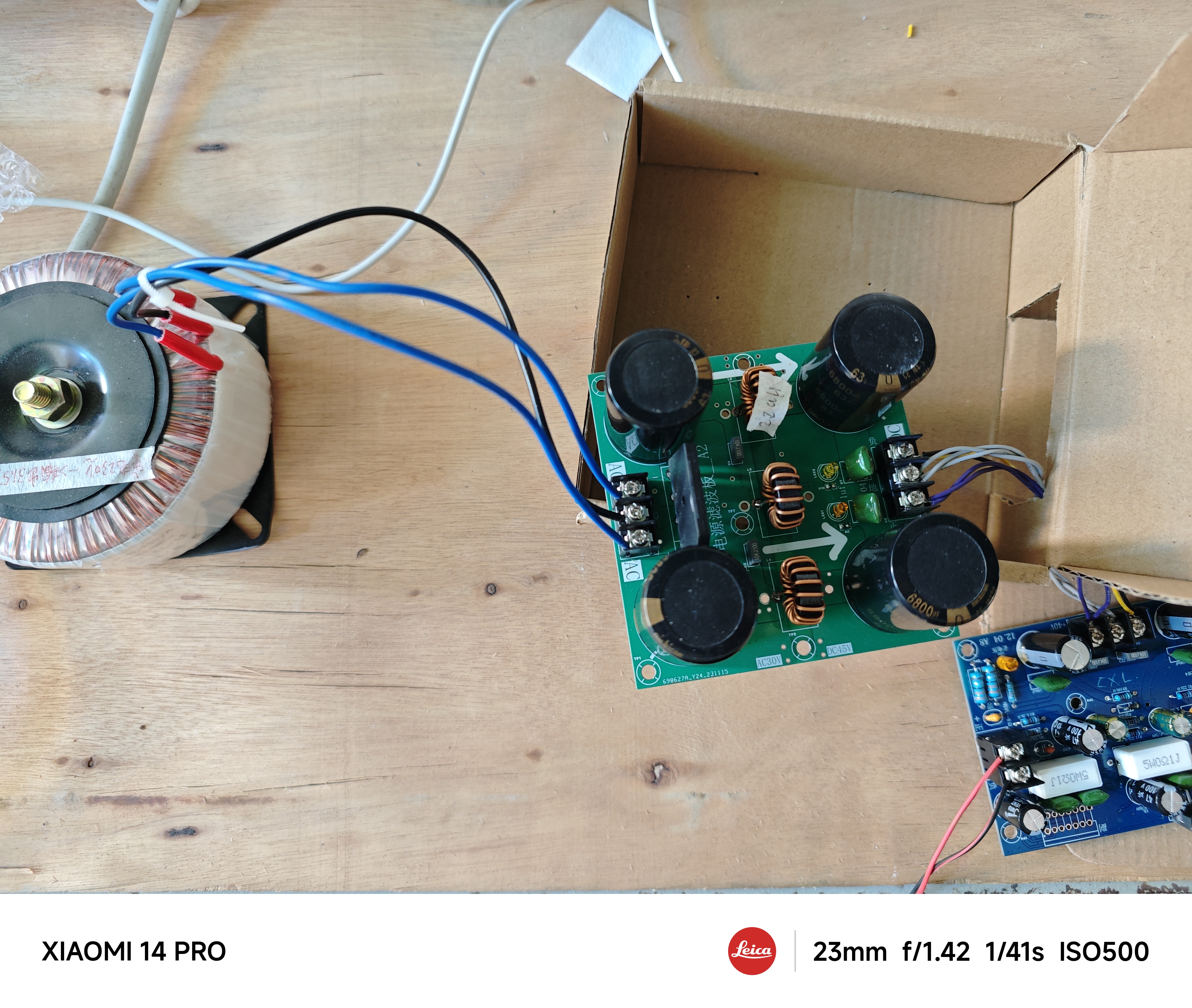
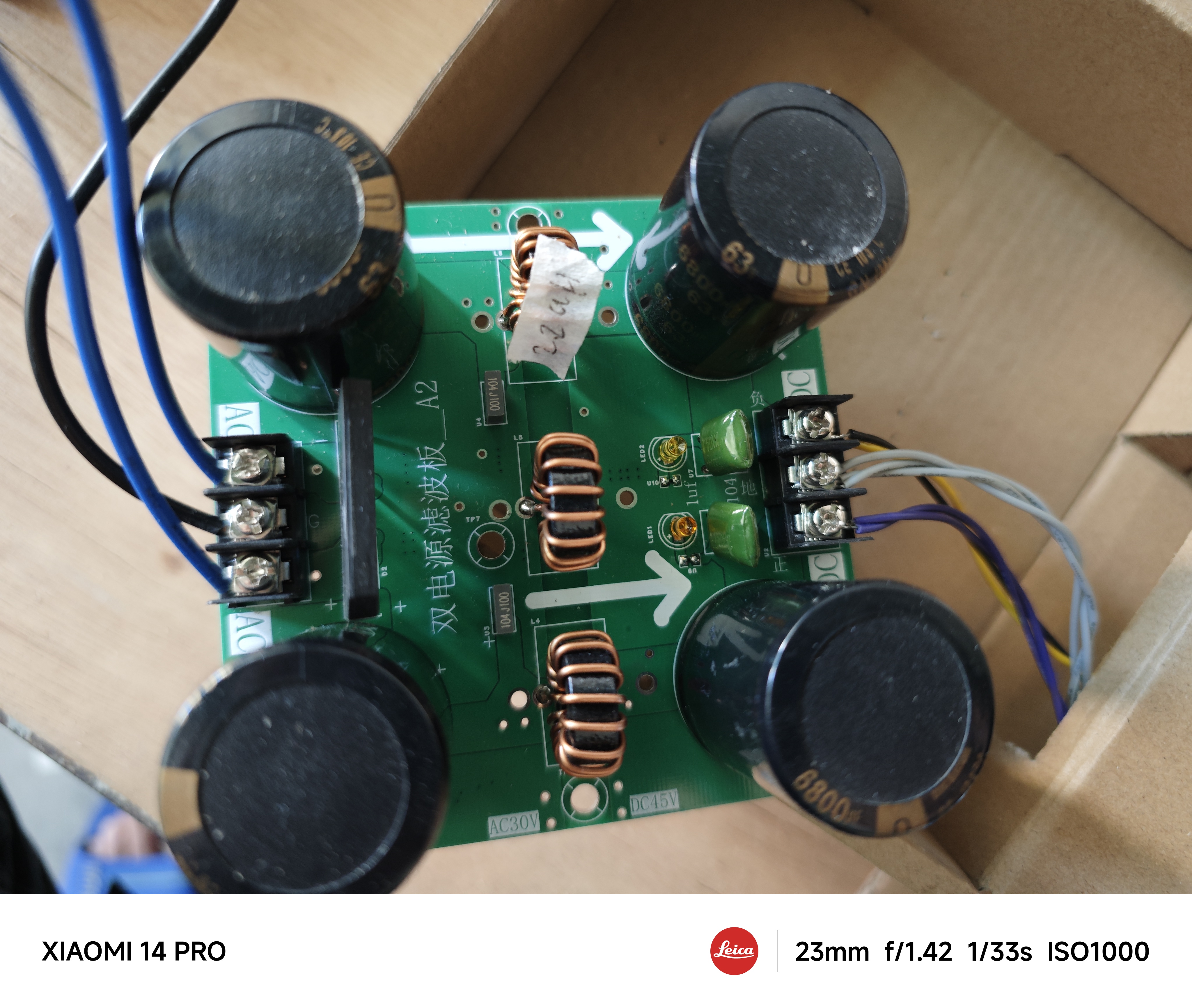
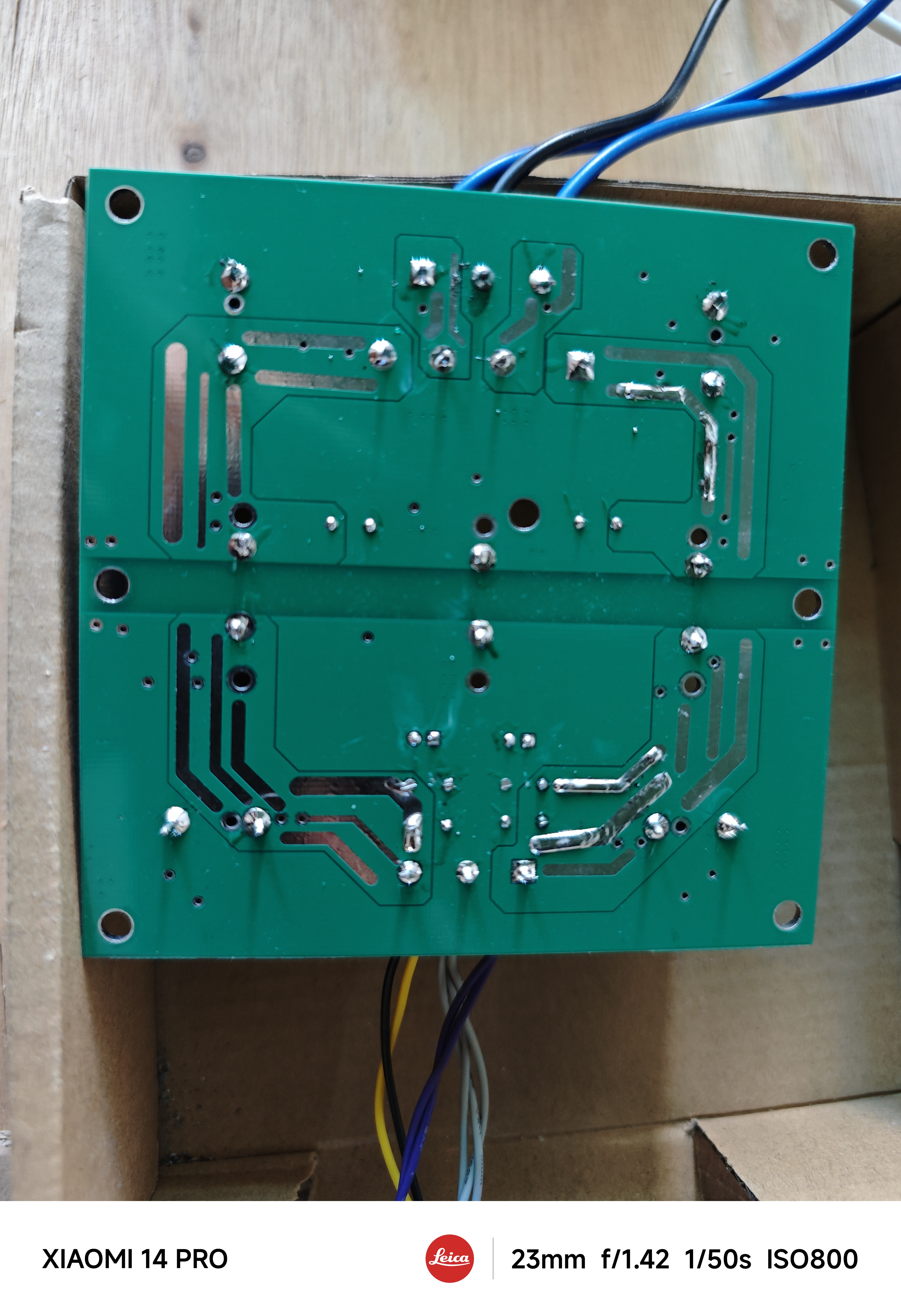
The power supply uses a dual-power supply filter (-30°C to 0°C and +30°C)
with rectification to produce 42V
for the 7293 amplifier board.
I'll post
the full specifications once the amplifier board is finished;
it
's not technically difficult
.

PDF_Power Supply Rectifier + Filter Board - A1.zip
Altium Power Supply Rectifier + Filter Board - A1.zip
PADS_Power Supply Rectifier + Filter Board-A1.zip
BOM_Power Supply Rectifier + Filter Board-A1.xlsx
96838
[Joint Laboratory] STM32 Line-Following Car | Taiyuan University of Technology
This small servo-driven tracking car can follow a pre-set route.
PDF_【Joint Laboratory】STM32 Line-Following Car_Taiyuan University of Technology.zip
Altium_【Joint Laboratory】STM32 Line-Following Car_ Taiyuan Institute of Technology.zip
PADS_【Joint Laboratory】STM32 Line-Following Car_ Taiyuan Institute of Technology.zip
BOM_【Joint Laboratory】STM32 Line-Following Car_Taiyuan University of Technology.xlsx
96839
Weld inspection device
The pipeline weld quality inspection device can identify weld problems at low cost, and determine the location of the problematic weld based on the length of the traction rope.
This circuit is designed to solve the problem of inspecting the quality of pipe welds. In use, it consists of a high-sensitivity light probe receiving matrix composed of multiple large-sized photoresistors. It is inspected in the pipe with a traction rope. When a weld with light leakage is encountered, the LED light on the main unit outside will light up as an alarm.
SCH_Schematic1_1_1-P1_2023-12-07.png
360 screenshot 20231207222413655.jpg
360 screenshot 20231207222444226.jpg
360 screenshot 20231207222612682.jpg
360 screenshot 20231207222641947.jpg
PDF_Weld Inspection Device.zip
Altium_weld inspection device.zip
PADS_Weld Inspection Device.zip
96840
Heart rate and blood oxygen monitoring
Wearable device for real-time monitoring of blood oxygen and heart rate.
With a heart rate and blood oxygenation detection module as its core, the data reception, calculation, and transmission are controlled by an STM32F103C8T6 microcontroller. A dedicated sensor acquires heart rate and blood oxygenation samples; only data meeting the criteria is used. Based on the sampled data, the heart rate and blood oxygenation values are calculated and displayed on an OLED screen along with their waveforms. Blood oxygenation measurement is mainly divided into transmissive and reflective methods, with transmissive methods currently being the mainstream, although their principles are similar. Both use light-emitting diodes (RED, IR, GREEN, and BLUE, etc.) to illuminate the measured area, and then a photodiode receives the transmitted/reflected light, converting the light signal into an electrical signal. A high-precision ADC then measures the reflected current to assess the oxygen content in the blood. The principle can be simplified as: light --> analog signal --> digital signal. Therefore, we need to control the current intensity and sampling rate of the LED light source, as well as the ADC accuracy (xbit) of the photosensitive sensor. This design is compact, lightweight, simple, and intuitive. Its watch-style design makes it easy to carry, and its high-frequency sampling sensor provides accurate data. An independent rechargeable lithium battery eliminates the hassle of cables. In short, this design has strong practical applications.
PDF_Heart Rate and Blood Oxygen Detection.zip
Altium_Heart Rate & Blood Oxygen Detection.zip
PADS_Heart Rate & Blood Oxygen Detection.zip
BOM_Heart Rate and Blood Oxygen Detection.xlsx
96841
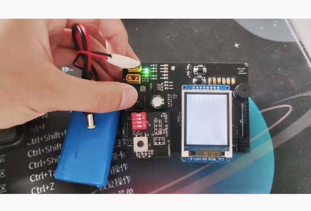
[Verified] QSL card with clock
The front features a digital display clock, and the back contains a QSL card.
I wanted to make a different kind of QSL card with a clock on a PCBA
. I need to constantly check the time during communication, and considering my previous experience with ESP8266 NTP clocks, I designed this.
Regarding the color silkscreen
verification board, to save costs, the size is kept under 1010 pixels and color silkscreening is not used. The original design was approximately 11.575cm in size, and 5 pieces cost 35 yuan.

The hardware and software are now working, and we can order the color silkscreened version.
Why does your QSL card design have a gold 5★?
Because I have many card designs. Based on the content of the image, the ease of obtaining (or rather, photographing? For an artist, it's probably the effort spent creating the image?), and the cost (for example, PCBAs are much more expensive than postcards), they are divided into four-star, limited five-star, and permanent five-star.
Communicating with me can get you virtual items… well, I don't know how to name them, but they're basically the kind used for gacha pulls. One of these items can be used for one "card draw" (i.e., applying for a QSL card, or simply a card lottery).
A maximum of 20 draws will yield one five-star card (commonly known as a small pity). If the five-star card obtained this time is not the current featured card, the next five-star card obtained will definitely be the current featured card (commonly known as a large pity).
(For details, please see my webpage or QRZ.com)
The PCB design uses a standard QSL card for
the back
silkscreen. Single-sided layout, no protrusions in the card area. The signature area is between the pins of the digital display. (Wow, OP!)

Standard silkscreen is white, and the card content is filled in with an oil-based pen. Green (or according to your own solder mask color) background, white template, black handwritten text.
White solder mask requires black silkscreen, resulting in white background with black text, regardless of whether the content is printed or handwritten.
Order Notes: Whether you choose color silkscreen or standard silkscreen, the content will display correctly. However, it is recommended to use light-colored solder mask, such as green and white.
The front features
two 0.56-inch digital tubes. One is a standard one, used to display the date (currently MMDD), and the other is the one with a colon indicating the clock, used to display the time.

For some reason, photos of the digital tubes taken with a mobile phone look terrible, even though they appear normal to the naked eye.
An NFC tag can be attached to the right digital tube; scanning it will directly launch Genshin Impact. If the card is shipped overseas, the tag content will be changed to launch the international version of Genshin Impact. The entire project
, excluding the PCBA,
includes the PCBA, code, and a contact webpage.
The support page for this card
(not finished yet, will be updated later)
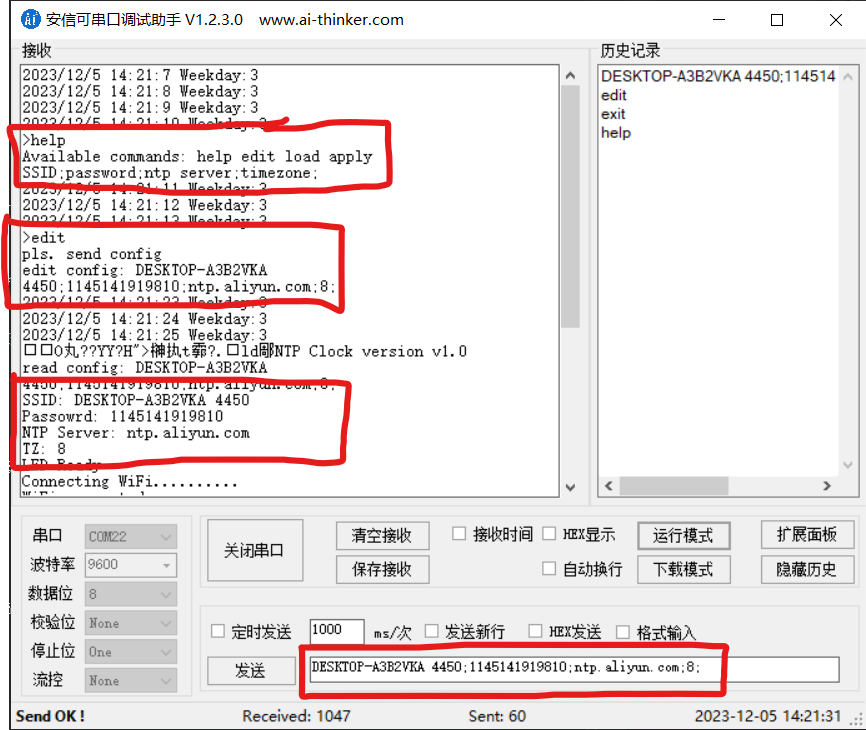
is coded on GitHub, but generally, you don't need to compile the code yourself; you can just tune parameters via serial port, which is convenient for users who don't know how to code or don't have the necessary environment.
Currently, parameter tuning is possible via serial port; the tuning method will be put on the webpage later. Essentially, entering the `help` command in the serial port will display all available commands and the configuration file format; it's somewhat similar to a shell scripting interface, in my opinion. (When I first wrote this part of the parameter tuning code, I wanted to use a shell-like approach.)
More...?
I posted it in the group, and the members immediately started brainstorming. Some suggested solar panels, some suggested e-ink screens, but I think that having an onboard lithium battery would be the simplest (and most practical) solution. So, maybe in my next life, I'll add a lithium battery charging and discharging circuit to this thing.
40D1FD60EAE0C6EEFA6E2FF8EAC7C7A1.mp4
PDF_【Verified】QSL Card with Clock.zip
Altium_【Verified】QSL Card with Clock.zip
PADS_【Verified】QSL Card with Clock.zip
BOM_【Verified】QSL Card with Clock.xlsx
96844
electronic


 京公网安备 11010802033920号

 BX5105


