1. Project Function Introduction:
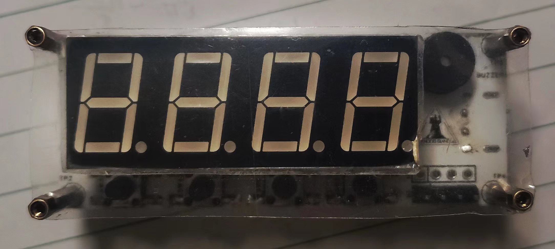
This desktop electronic clock is implemented using the R7FA2E1A72DFL chip. The digital display uses a four-digit 0.56-inch common cathode LED display (without a colon), and the temperature and humidity display uses a DHT11 chip.
The clock uses the chip's built-in clock, supports a reset button, SWD download circuit, and I2C for easy downloading and debugging.
2. Project Attributes: This project
was created as part of the 2023 JLCPCB Summer Training Project.
3. Open Source License
: The project uses the GPL 3.0 open source license; all hardware and software are open source.
4. Hardware
PCB Design: The PCB uses JLCPCB Professional Edition EDA.
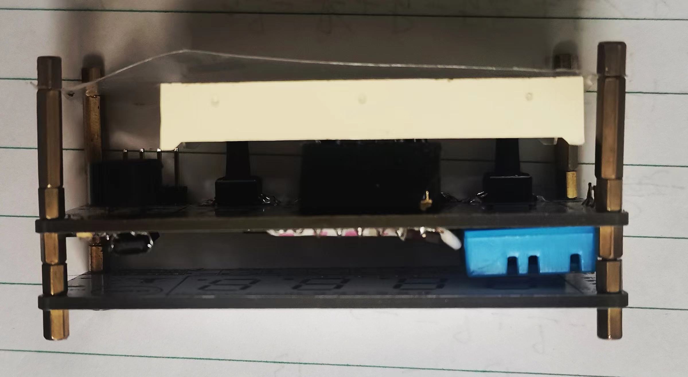
The casing is made from surplus printed panels, M2 studs, and plastic casings used for chip packaging.
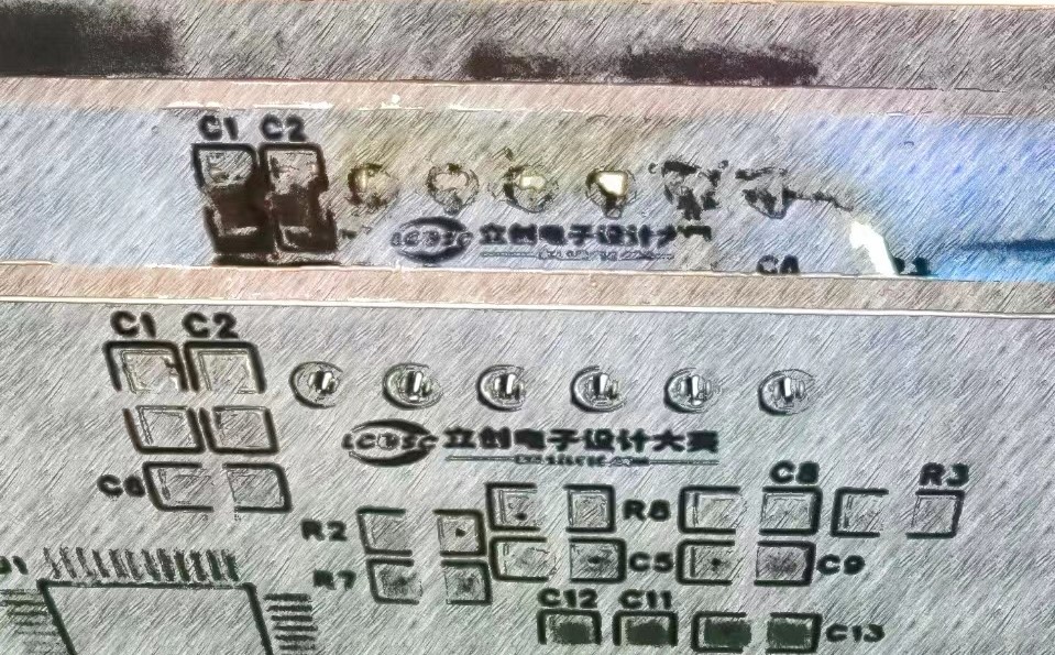
If the LED display fails to display after soldering, it's a soldering issue; check for
cold solder joints. To remove the LED display, use a pry bar, apply a suitable amount of solder to the holes on both sides of the LED display, heat the soldering iron to approximately 400 degrees Celsius, repeatedly heat the holes, and then gently pry the LED display while tapping.
Patience is key; otherwise, you might accidentally remove the solder pads.
Rosin can be added to the main controller to prevent solder bridging.
5. Software:
The software uses Keil for coding and Renesas RA Smart Configurator for pin and clock configuration. The buzzer's sound is controlled by adding "buzzer_num"
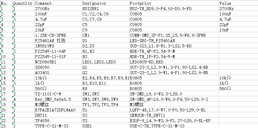
in "timer_smg.c". The number 0 on the project cover is particularly bright because the display refreshes one digit at a time, and the rapid refresh makes it appear bright. Other possibilities include poor pin contact. Due to a circuit issue, buttons 3 and 4 were physically positioned incorrectly; this has been corrected in the software, and their positions are now in the "set_smg_button()" function in "timer_smg.c". Button 1 modifies the time; pressing it on the humidity and temperature display screen returns to the displayed time. Button 2 decreases the time. Button 3 increases the time. Button 4, when pressed once, displays the temperature in degrees Celsius (first digit shows C), and the second press displays the humidity (first digit shows H). Pressing it again returns to the displayed time. Pressing it while modifying the time saves the time and returns to the displayed time. Note that due to debugging issues, after multiple soldering attempts, two pins on the chip became detached (the image is not very clear, but there is no solder bridging) . The damaged pins are P103 and P104, which are connected to SEG_A and SEG_1 respectively. Therefore, SEG_A is now connected to P111, and SEG_1 is connected to P201. If you attempt to copy this, you need to modify "BSP_IO_PORT_**_PIN_**" in SMG_A_OPEN, SMG_A_CLOSE, SMG_1_OPEN, and SMG_1_CLOSE in smg.h to 01-03 and 01-04 respectively. The personal program is "Clock.hex", the original pin program is "Clock_Org.hex", the original version without buzzer is "Clock_NoBeep.hex", and other programs are "src.rar". "hal_entry.c" was forgotten but has been added. 6. BOM List 9 7. Competition Logo Verification 8. Demo your project and record a video to upload to the LCSC Electronics Competition: #8thLCSC Electronics Competition# Voice Clock Appearance Showcase: Top Button Side Back Bottom Chip Side


 京公网安备 11010802033920号

 LTL-4254-0D1A


