The schematic diagram
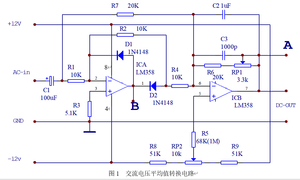
shows RP1 and RP2S for adjusting the measurement accuracy (adjust before use).
Adjustment method:
1. Connect positive and negative power supplies, measure at point A with a multimeter, then adjust RP2, making the multimeter reading as close to 0 as possible; 2.
Connect positive and negative power supplies and a 1Vrms, 100Hz signal, measure at point A with a multimeter, then adjust RP1, making the multimeter reading as close to 1 as possible.
Principle analysis:
Break this down into two operational amplifier circuits, analyze them separately, and then superimpose at
point B: (Simplified)
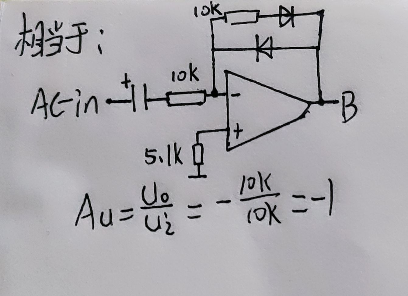
Alternating current has positive and negative cycles
. Positive cycle: The upper diode conducts, the lower diode does not conduct. It is reverse amplified, with a magnification factor of -1, so the positive half-cycle is a waveform of equal magnitude but opposite phase to the input waveform. Negative
half-cycle: The upper diode does not conduct, the lower diode conducts. The voltage is zero.
That is: output a half-wave, and this half-wave is opposite to the input.
Point A: (simplified diagram)
Here, A and B are connected together by R4, which is not considered for now, and will be calculated when superimposed.
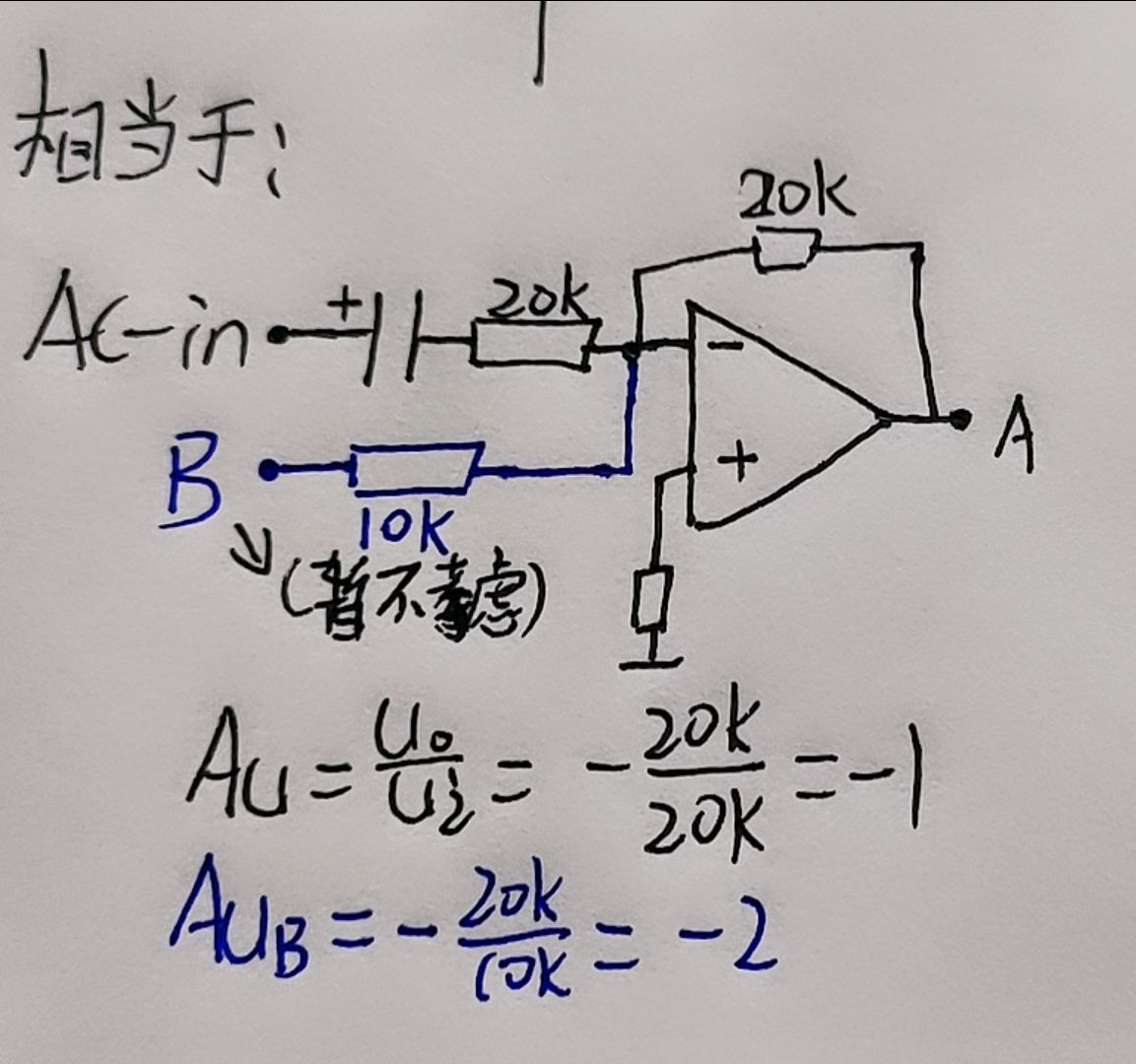
The blue text in the diagram is not considered here.
This is a reverse amplification, and the amplification factor is -1, so it is a waveform that is equal in size and opposite in phase to the input waveform.
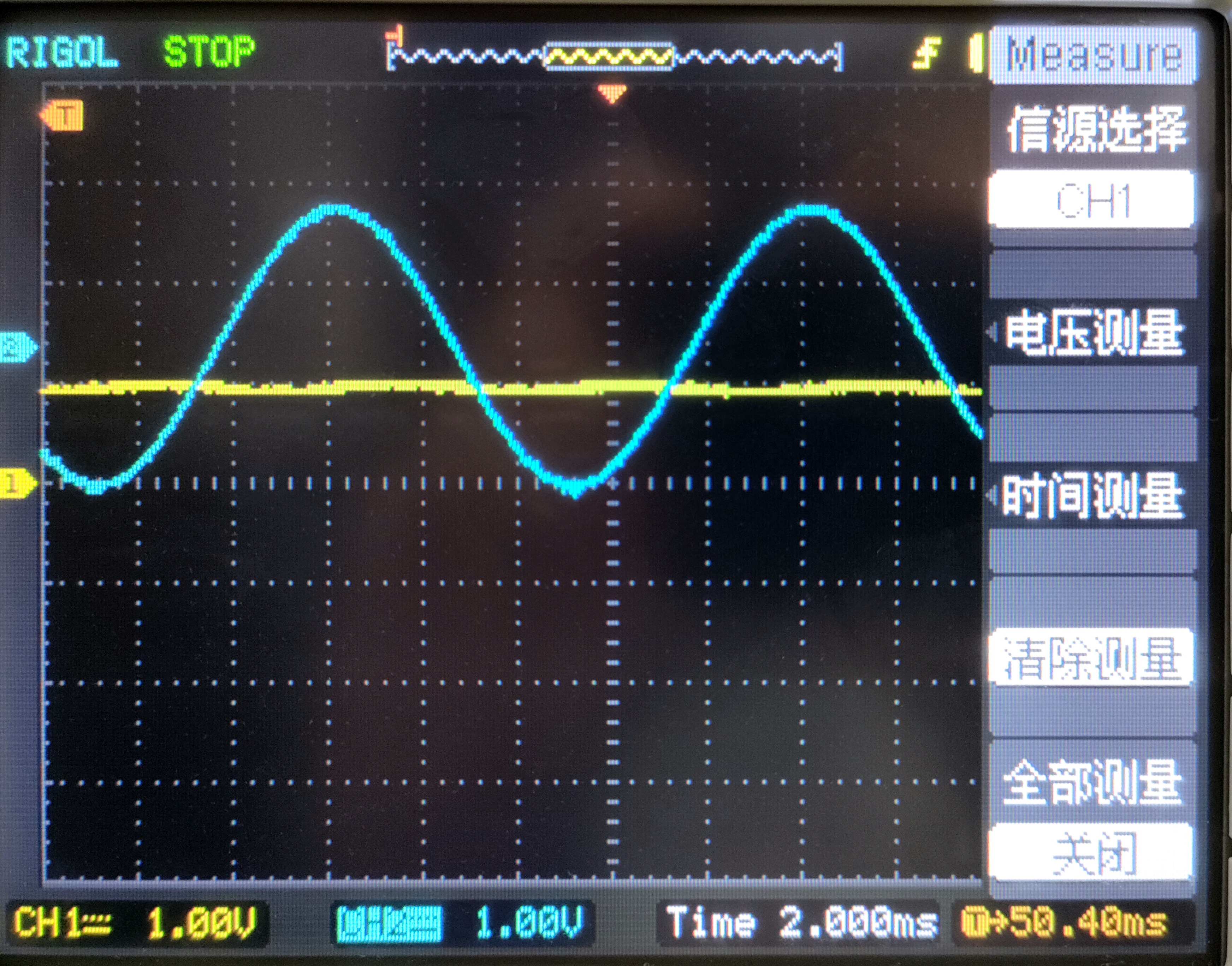
The following is the waveform of point A at 1KHZ, 1V (blue line).
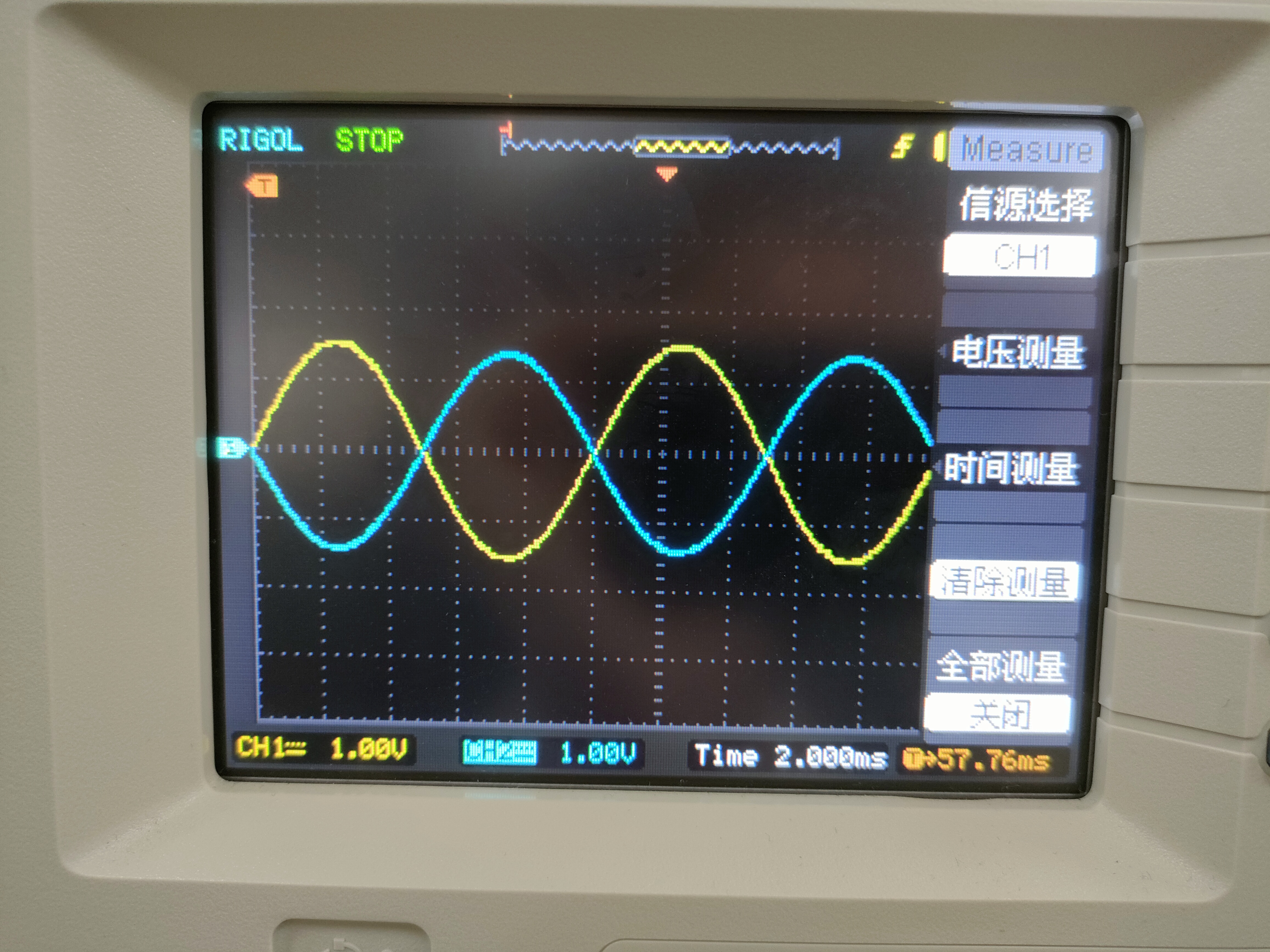
This waveform is the waveform with R4 and C2 disconnected. Disconnecting R4 means disconnecting the connection of the previous op-amp.
C2 is a filtering function. Disconnecting C2 is to better see the waveform
superposition analysis:
disconnect R7 and C2.
R7: AC power only enters from the first op-amp, disconnecting the connection between AC power and the second op-amp.
C2: Remove the filtering function. Disconnecting C2 is to better see the waveform.
From the previous analysis of point B, at this time, point B is a half-slope and opposite;
point B then goes to the second op-amp, forming a reverse amplification, with an amplification factor of -2;
that is to say, point B is amplified again by inversion, so after two inversions, this waveform becomes a positive half-slope and twice the size (-1*-2=2).
The waveform at point A (input blue line, output yellow line)
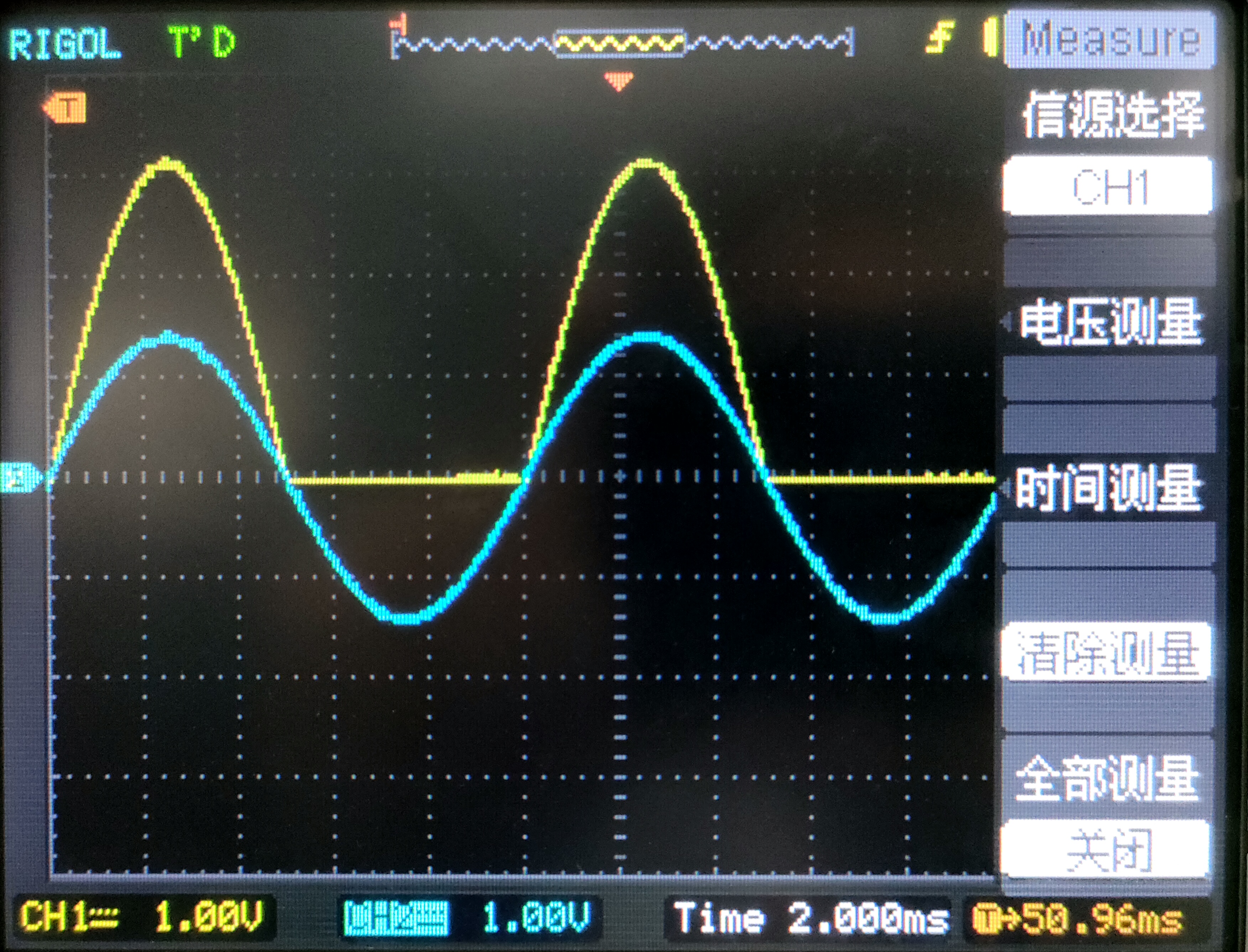
is shown below. Next, consider disconnecting only C2 and analyzing the waveform before filtering
: this is the superposition of the waveform shown above and the waveform analyzed at point A.
The inverted waveform superimposed with the double half-slope equals the full wave.
The waveform at point A (input blue line, output yellow line)

is shown below. This basically concludes the analysis. Finally, reconnect C2 for filtering.
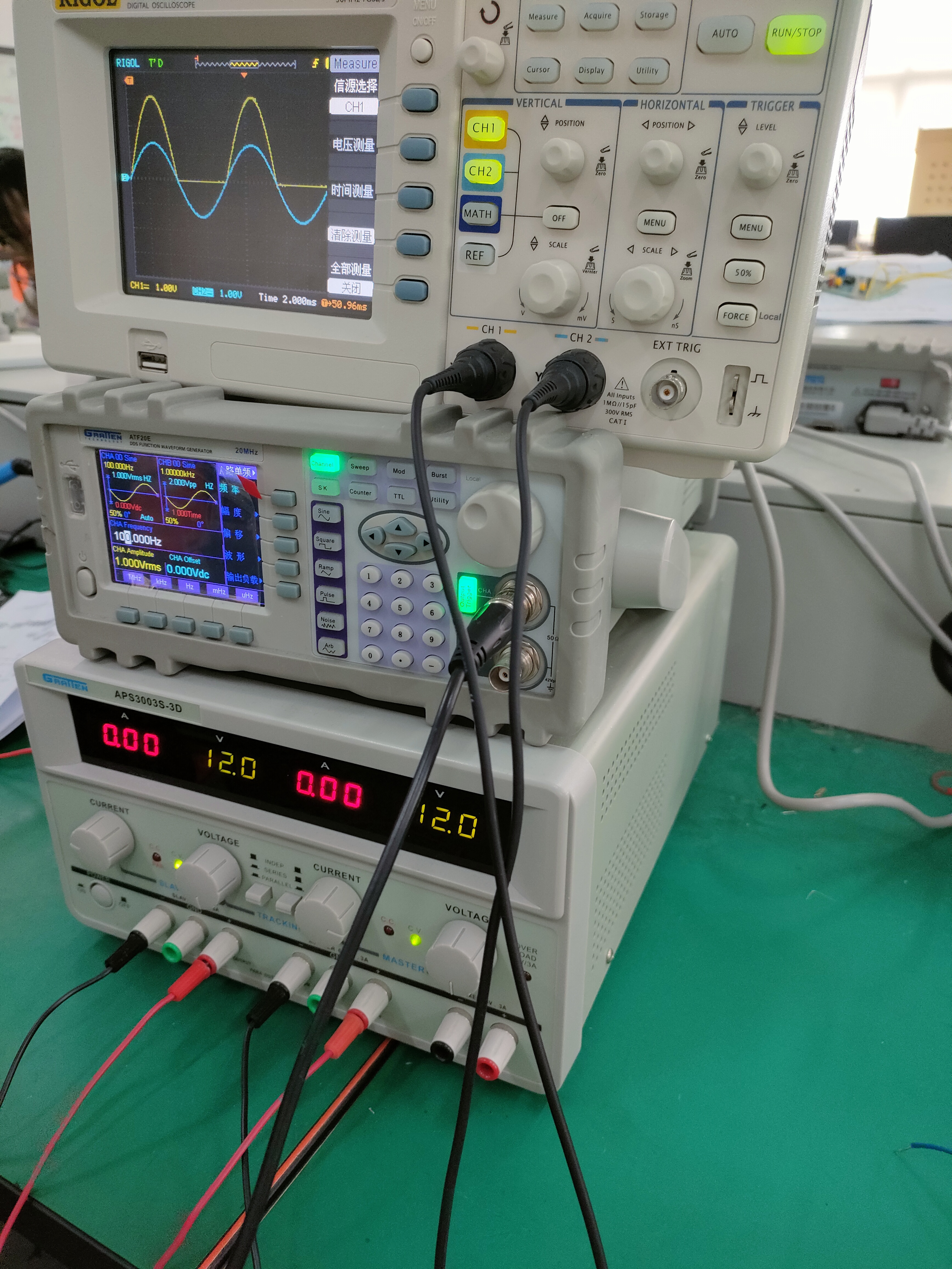
This converts the 1Vrms, 100Hz AC power into 1V DC
power. (Physical demonstration)
PDF_AC Voltage Average Converter.zip
Altium AC Voltage Averaging Converter.zip
PADS_AC Voltage Average Converter.zip
BOM_AC Voltage Average Converter.xlsx
96942
pirtk
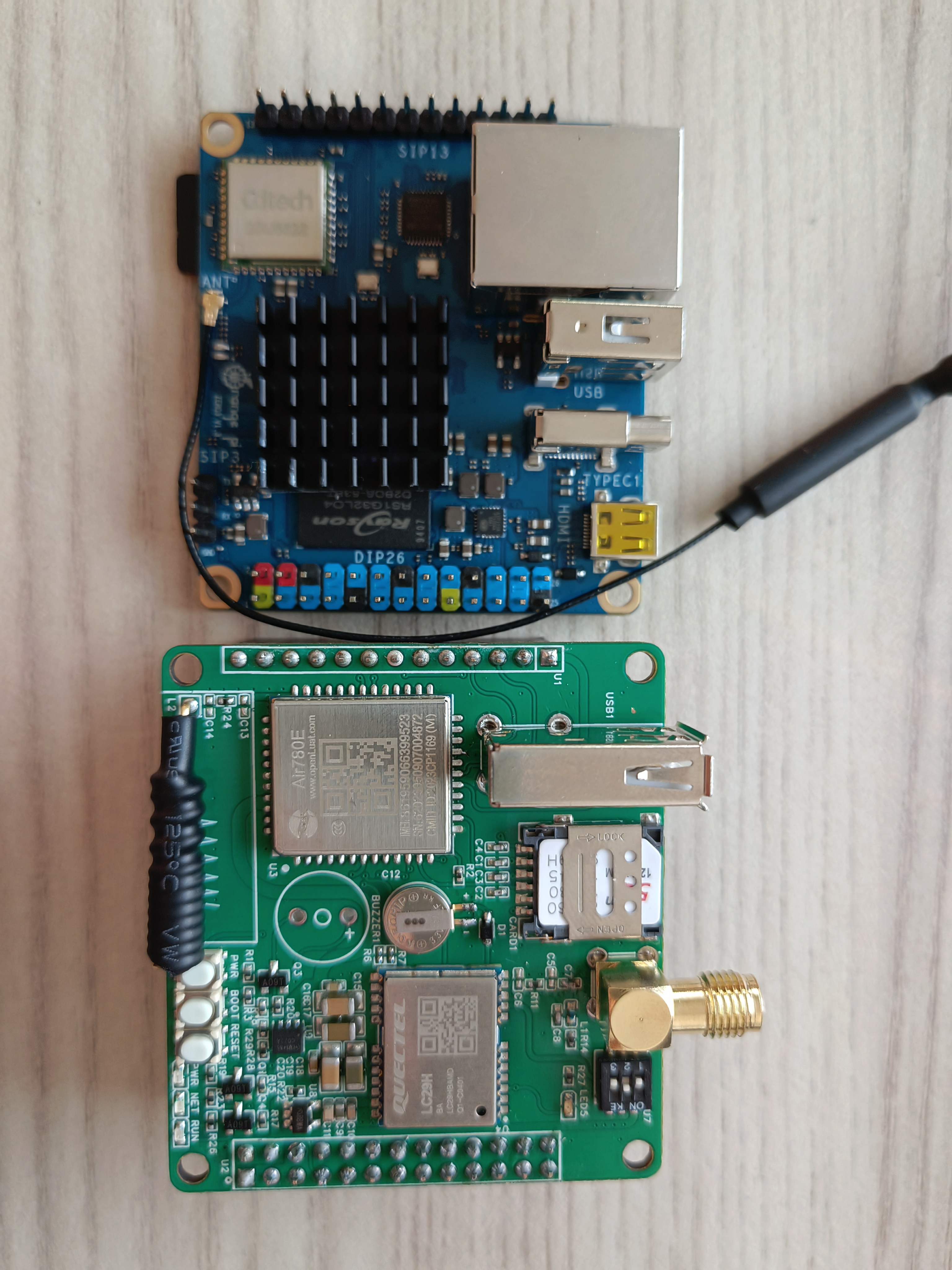
LTE+GNSS expansion board designed for Orangepi Zero3
Functional Description:
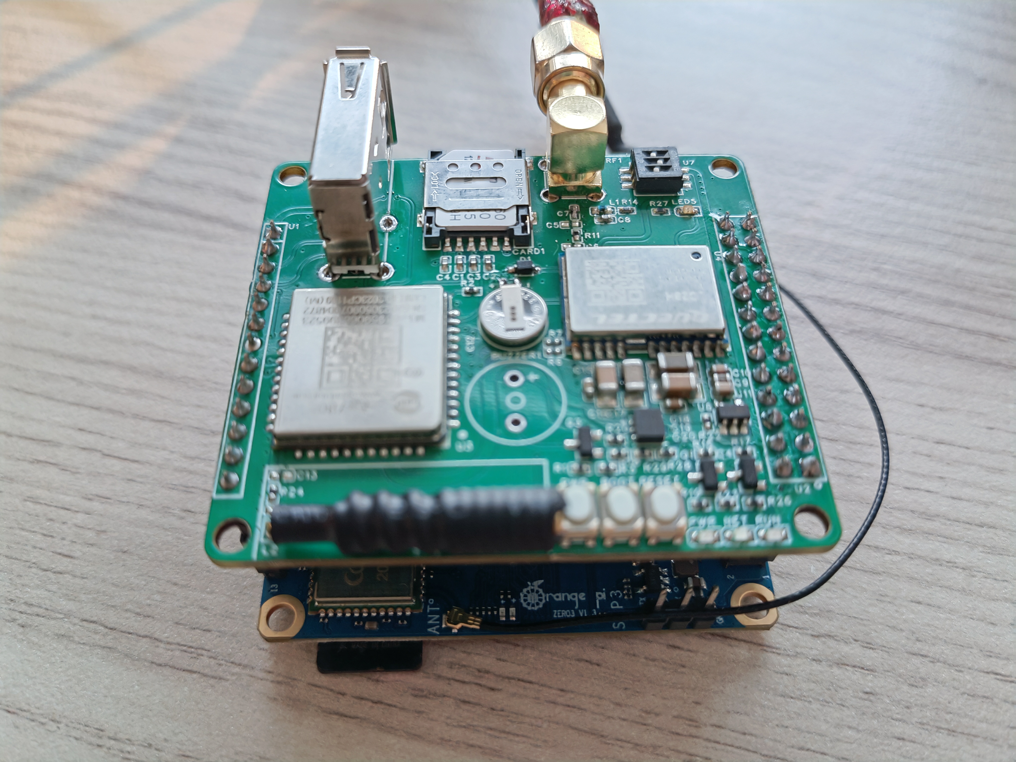
Pirtk is an LTE+GNSS expansion board designed for Orangepi Zero3, enabling Orangepi Zero3 to connect to the network via LTE. The GNSS module can be used for CORS self-hosting or algorithm research.
Hardware Description
: Interfaces: USB
Antenna: Onboard 4G antenna + SMA terminal (GNSS antenna)
4G: Hozon Air780 module, supports patch SIM card or nanoSIM
GNSS: Quectel LC29H module, supports RTK positioning, supports raw observation output
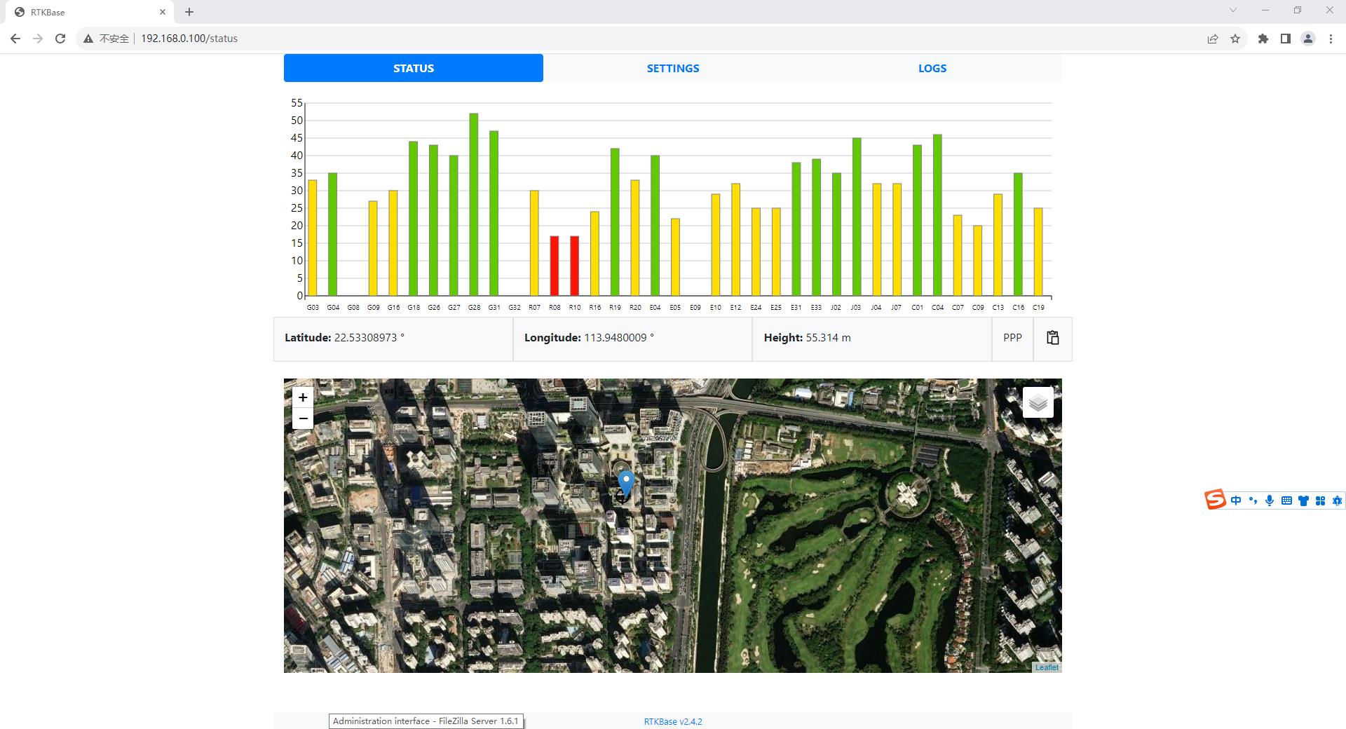
Software Description:
Orangepi Zero3 supports Ubuntu system, and the following software can be freely installed
: RTKBase: Open source CORS self-hosting software
Traccar: Open source positioning and tracking platform software
OpenCaster: Self-developed Caster software
RTKLIB: Open source positioning algorithm, research-specific
physical object
software Image Code Block:
PDF_pirtk.zip
Altium_pirtk.zip
PADS_pirtk.zip
BOM_pirtk.xlsx
96943
Desktop electronic clock
A simple desktop clock based on the electronic clock from LCSC Training Camp.
1. The main
control circuit uses a Renesas R7 series chip, with each pin exposed.

2. A passive buzzer driver circuit is used as the alarm clock module .

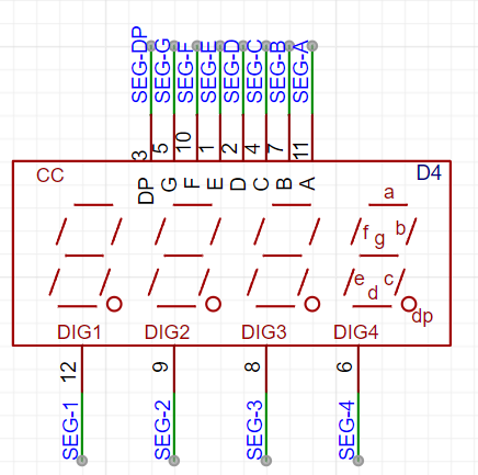
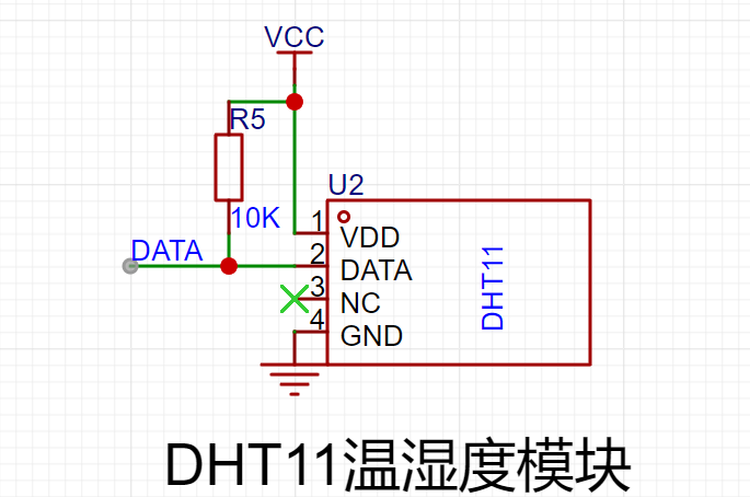
3. The display module
uses software to drive a cathode ray tube to display the time, date, temperature, and humidity.
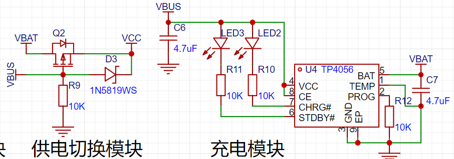
4. The power module
can be powered via USB or a coin cell battery.

A TP4056 linear charging chip is used for charging management, and it is packaged in an ESOP8 package to supply power to both the USB port and the adapter.
Second Board Desktop Electronic Clock.zip
BOM.xlsx
RA2E1_Clock.hex
Tool shaolu Project.zip
PDF_Desktop Electronic Clock.zip
Altium Desktop Electronic Clock.zip
PADS_Desktop Electronic Clock.zip
96944
ESP32 debugger
The functionality has been verified by board testing. The USB expansion chip CH334R is used to expand 4 USB signals, and one USB signal and serial port are directly connected to ESP32 S3/C3. An STM32G030F6P6 is added to collect sensor data.
The functionality has been verified by board testing. The USB expansion chip CH334R is used to expand 4 USB signals, and one USB signal and serial port are directly connected to ESP32 S3/C3. An STM32G030F6P6 is added to collect sensor data.
PDF_ESP32 debugger.zip
Altium_ESP32 debugger.zip
PADS_ESP32 debugger.zip
BOM_ESP32 debugger.xlsx
96945
TDA2050 Mono Amplifier Board
The completely independent amplifier circuitry provides better separation and facilitates installation.
The two channels use completely identical and independent power supply and amplification circuits. In addition, LCSC's color printing gold process not only enhances the appearance but also reduces wire resistance and power supply internal resistance, thereby achieving better stereo separation. The high and low frequencies are improved, and the effect is very good.
PDF_TDA2050 Mono Amplifier Board.zip
Altium_TDA2050 mono amplifier board.zip
PADS_TDA2050 Mono Amplifier Board.zip
BOM_TDA2050 Mono Amplifier Board.xlsx
96947
docking station + STM32 keypad
I often lamented the lack of sufficient USB ports on my computer and the absence of a simple Ctrl+C/V function, hence this 2-in-1 solution. Unfortunately, I forgot to add a 1.5k pull-up resistor to the USB port. This has already been fixed in the project, allowing it to run at full USB 2.0 speeds.
Essentially, it's a USB docking station plus an STM32 keyboard. There aren't any ready-made products I need on the market, and since I've been playing with STM32 recently, I decided to try it myself. Any chip that supports HID will do; I haven't tried other chips yet.
Some points:
1. Due to the high integration, soldering is difficult, which is not user-friendly for beginners like me.
2. The key actuation force is a bit high, making it not smooth to press. The keys in my project are 260GF small keys.
3. I initially planned to make a 4x4 matrix, but found that I didn't need that many, so I reduced the number. There's still room for development on the back.
4. Other types of Type-C connectors can be chosen; differential pair wiring is sufficient.
5. Since this is just for fun, no protection circuit was designed, so it's not anti-static.
usb_keybord.rar
PDF_Dockyard + STM32 Keyboard.zip
Altium_Dock + STM32 Keyboard.zip
PADS_Dock + STM32 Keyboard.zip
96948
electronic


 京公网安备 11010802033920号

 APM4804KC-TU


