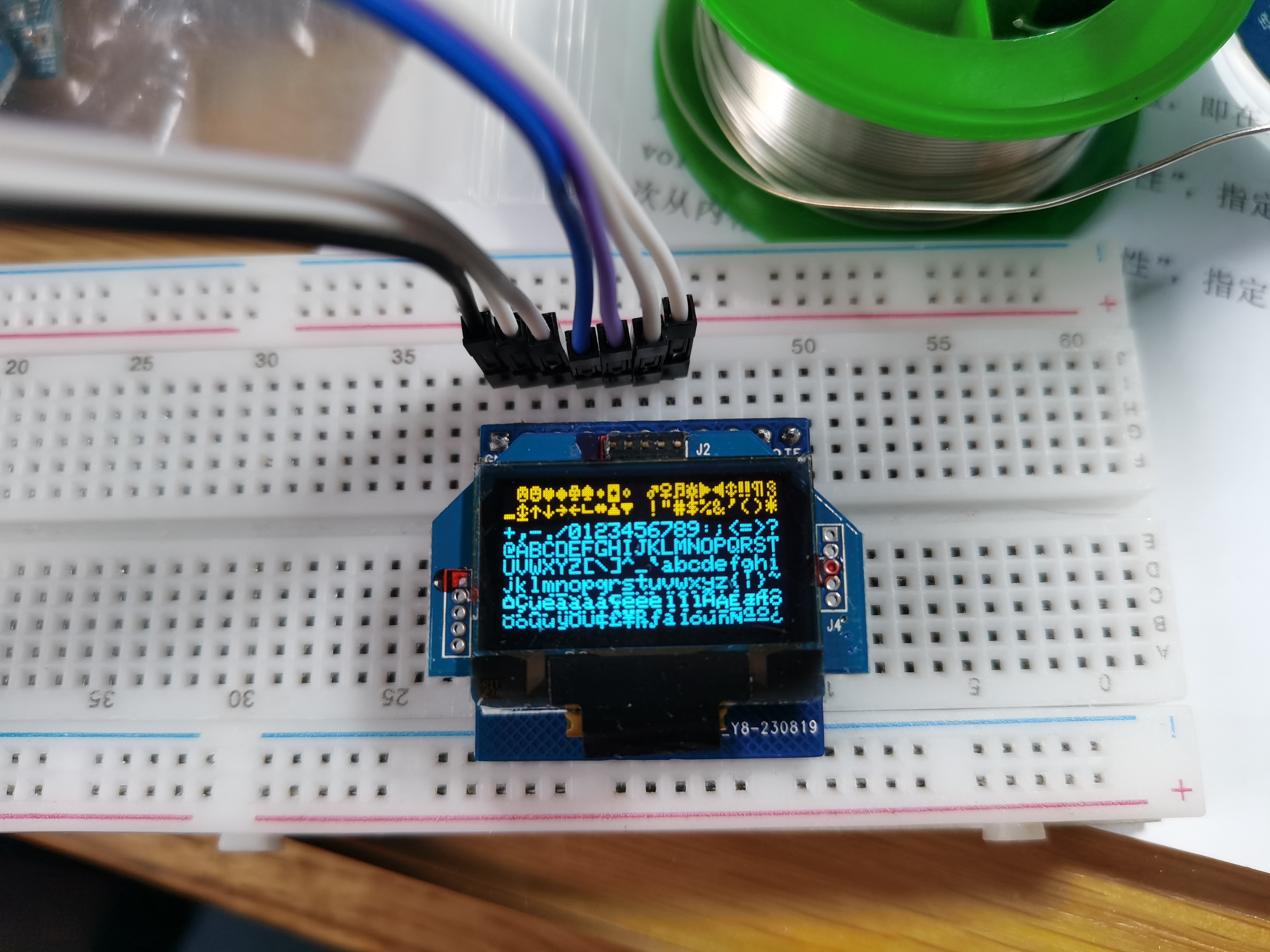
1. OLED screen adapter board;
3. ST7789 color screen driver board;
4. LCD12864 driver board.
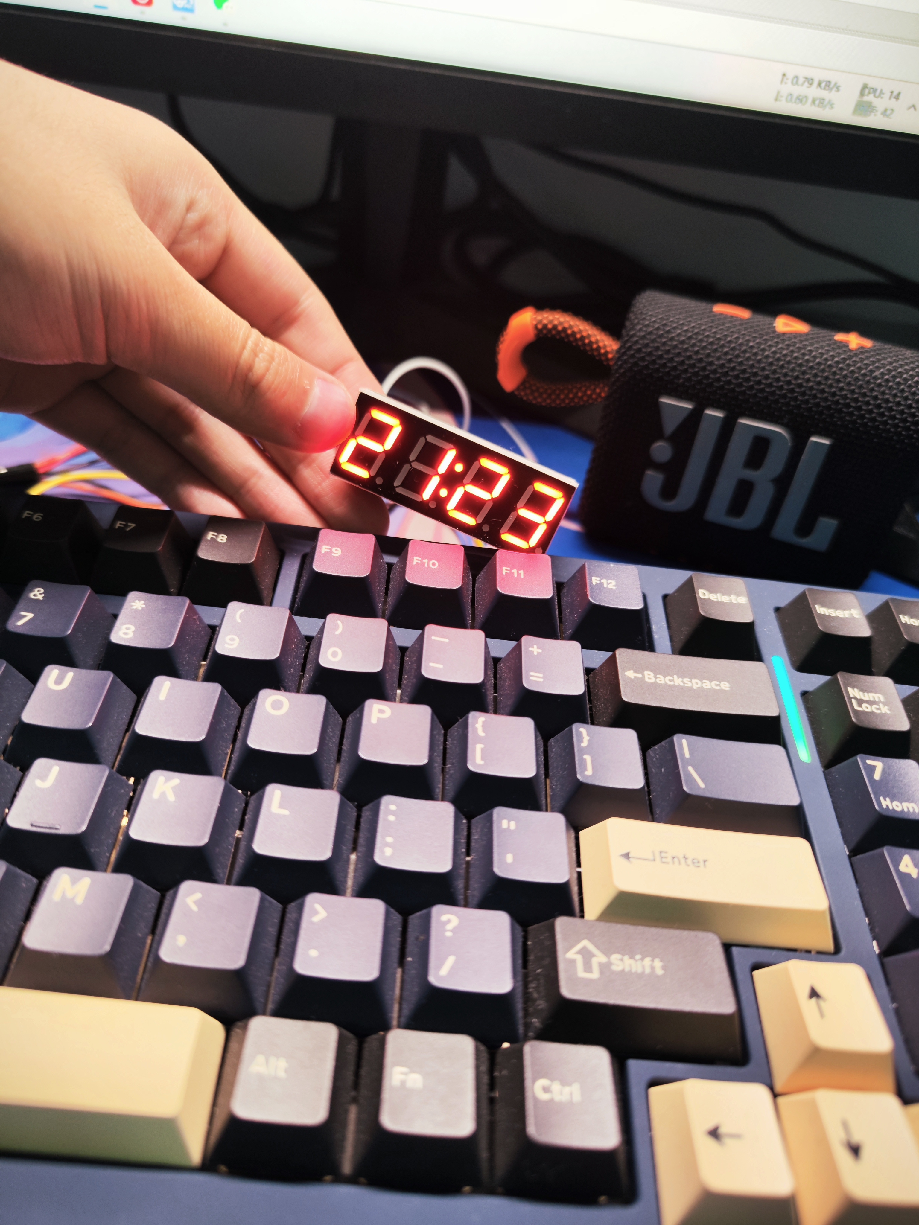
This project uses air001's HAL library and currently implements functions such as time display, time setting, Pomodoro timer, temperature and humidity display, and brightness adjustment. Because it's a new project, the goal is to minimize its size, so it's currently very small. Please
be gentle with your feedback, experts!
Introduction
: This project uses the Air001 main controller (I had too many on hand and wanted to use them up,
so this project came about). The Air001 digital clock
is a good example; if you've clicked on this, I bet you have a lot of Air001s too...
Any useful suggestions are welcome!
Regarding cost,
I had the PCB custom-made and bought 5 sets of components, costing approximately 70 (note: 5 sets! 5 sets!!!).
Version iteration
0.1v is just a prototype, emmmm, there's no way around it... Currently implemented functions
include: time display (year, month, day, hour, minute switching);
time setting (year, month, day, hour, minute setting). Why isn't there a second function? (That's a separate function; I don't have time to write it due to finals).
Temperature and humidity display (there's a slight issue with the PCB design; it will be revised). The current version v0.1
implements a Pomodoro timer, currently capable of counting down 30 minutes, 60 minutes, and 90 minutes. Three options
and a countdown (originally, I wanted to just modify the timestamp in the code; this function will be released later for direct
brightness switching (because the digital tube consumes too much power!).
The button scanning method uses interrupts (I'm an idiot, don't worry about that, right?).
Thanks to Professor Luo: it's not like the function to be implemented can't be used.
Modify the PCB to a four-layer board,
optimize the circuit, change to a smaller LOD, and change the position of the AHT20 (if you ask me, can the temperature measured next to the LOD be accurate...).
Change the `dealy` in the code to `sleep` or something else to further reduce power consumption.
Adjust the time via serial port to set the countdown.
Implement battery expansion board Type-C charging, and also include USB to...
Please include my contact information regarding the TTL chip . If there are many people, I can create a group QAQ. I'm too lazy to
upload the code
to GitHub, so I've just uploaded a compressed file.
How to use:

The left and right buttons are for page turning, and
the middle button is for confirming and switching menus.
Press the left and right buttons on the time interface to switch clock display modes.
Remember to release the button after long-pressing! Otherwise, it won't respond (I'm an idiot; why did I write my own button driver?).
The button driver setting time is a bit long (it should be long-press).
Long-press the left button on the clock interface to set the time!
Long-press the middle button to enter the switching interface
: 0. Clock, 1. Temperature, 2. Humidity, 3. Pomodoro Technique, 4. Countdown (set to 2025 postgraduate entrance exam time), 5. Brightness setting.
Next batch of pictures (I'm too lazy to solder them, but the board is finished).

Schematic

demonstration video.
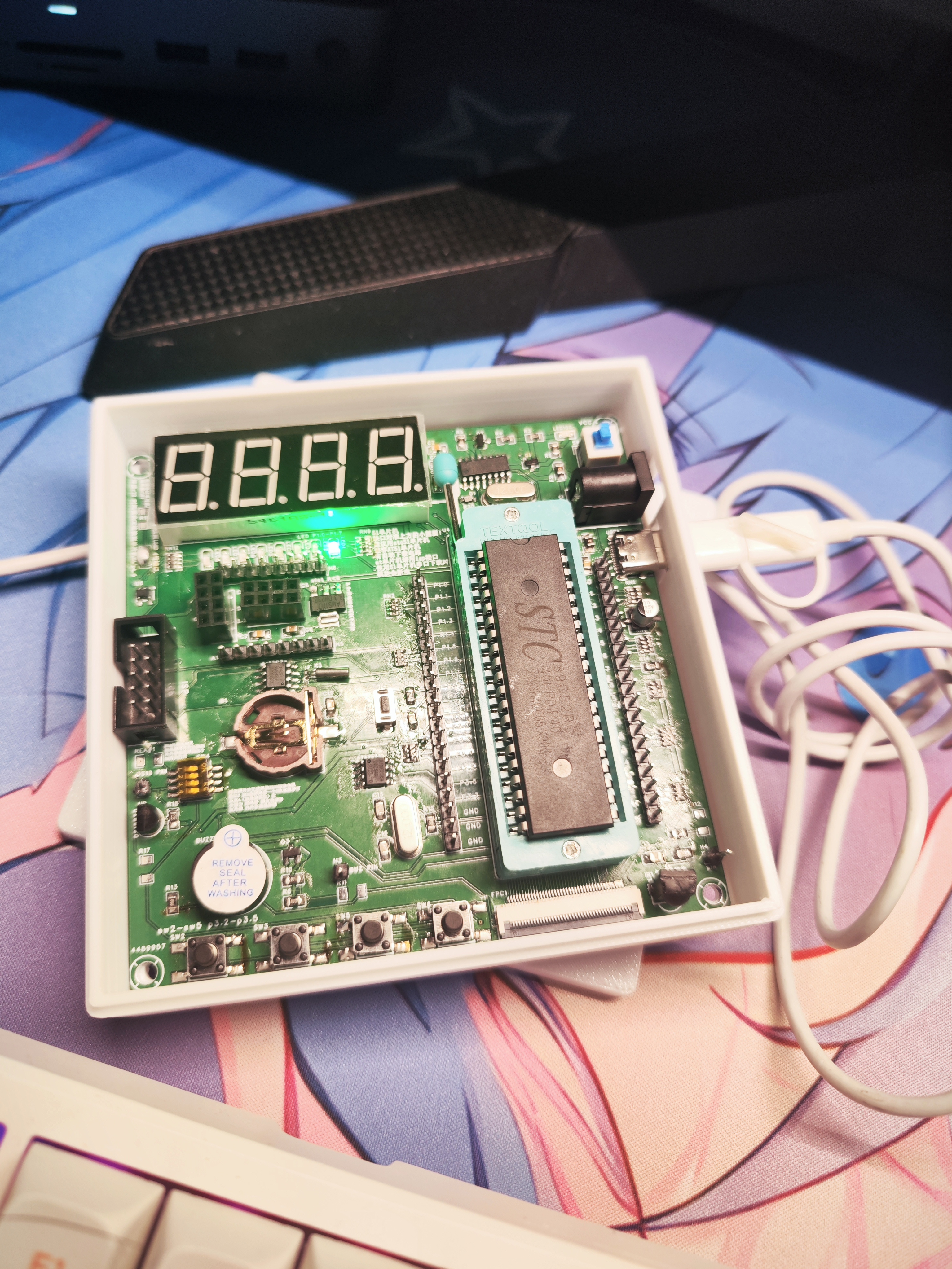
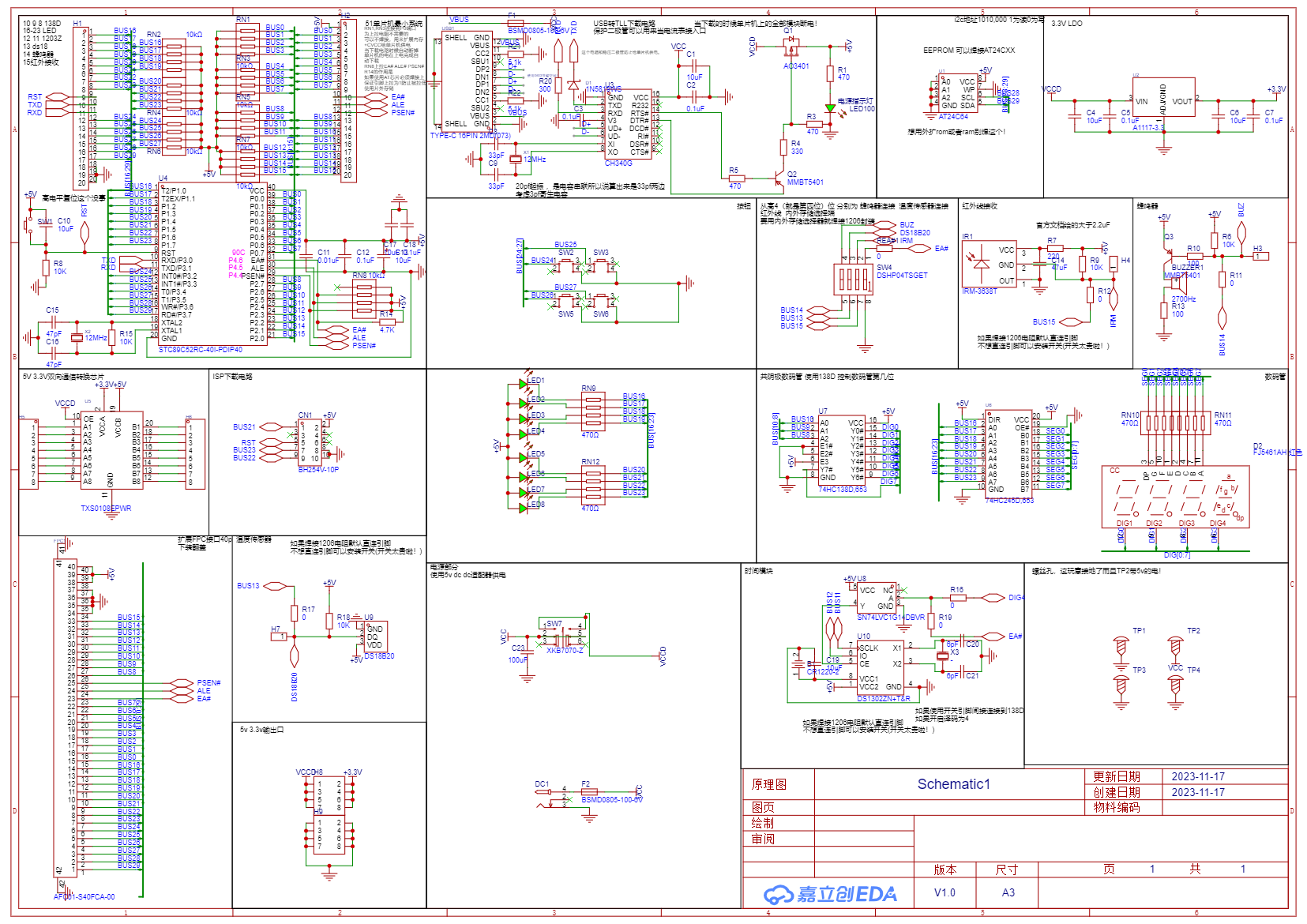
This project
is a creation based on my ideas for a 51 microcontroller development board
. Recently, my school offered a 51 microcontroller course, and I created this project with a learning attitude. I also hope to add my own ideas and make some improvements to the project. Here are
some things I did:
Compared to other development boards on the market, this board has an ISP interface that can be used with STC. Alternatively, you can use either an AT51 microcontroller or an STC chip (although an STC chip is sufficient
and a Type-C interface is added, reducing the need for cables; it has a built-in CH340G chip for direct programming and an automatic download circuit, eliminating the need for a switching power supply for downloading
– most importantly, and also my biggest mistake). If you want to expand with RAM or ROM, that's also possible, as the development board has DIP switches for these functions (if you really want to try it out...).
The bottom has an FPC cable to help you quickly connect an external expansion board. (Of course, you'll need to modify
the M3 screw post; the upper right corner connects to the VCC for easy stacking, and the other copper posts are grounded).
It provides 3.3V power and TXS0108 bidirectional level conversion communication,
eliminating the need for a 3.3V module with a 5V level for the 51 microcontroller.
The rest are optional:
8 LEDs, an infrared receiver, a buzzer, a common cathode digital tube driven by 74HC138 and 74HC245,
a built-in DS1302 time chip, a DS18B20 temperature chip, 4 buttons, and an AT24C02. The memory chip includes ISP and TTL auto-download circuitry
(CH340G), the USB-to-serial chip has a step-down chip that can output 3.3V, and the TXS0108 bidirectional level conversion communication chip
board was prototyped several times, but thankfully all the problems were solved (thanks to JLCPCB QAQ
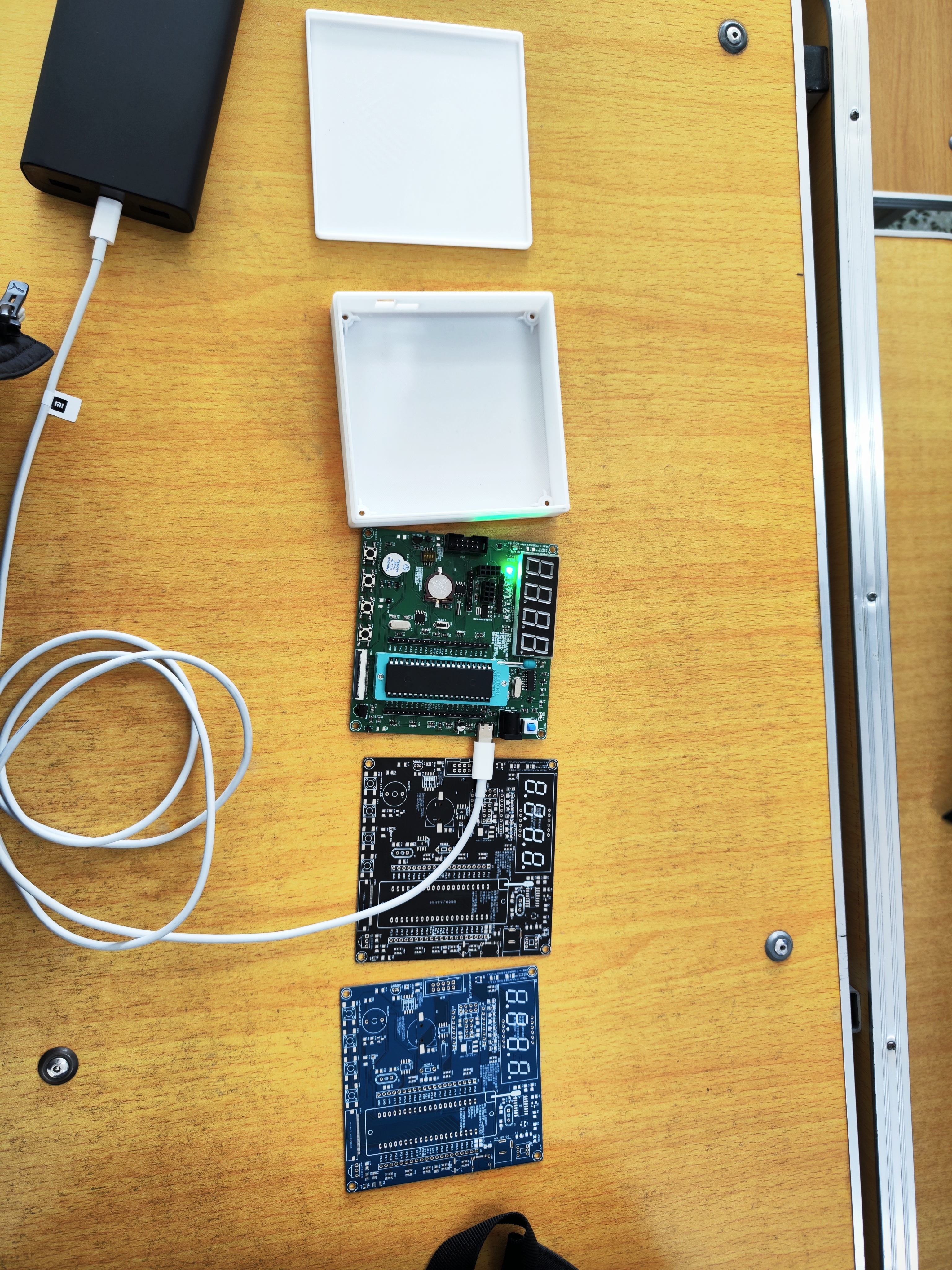
for providing the schematic).
VID_20231117_000740.mp4
SCH_Schematic1_2023-11-17.pdf
PDF_51 Microcontroller Development Board (Compatible with STC and AT chips).zip
Altium_51 microcontroller development board (compatible with STC and AT chips).zip
PADS_51 Microcontroller Development Board (Compatible with STC and AT chips).zip
96980
A four-way quiz buzzer system based on CD4511
A four-way quiz buzzer system based on CD4511
This system features a four-way answer-grabbing function, with reset and latching capabilities.
The engineering description of the CD4511-
based four-way answer-grabbing device for digital tube displays is as follows: 1. Hardware Design: The core of the system is a four-way answer-grabbing device composed of the CD4511 integrated circuit. The CD4511 is a BCD-to-seven-segment decoder used to drive common-cathode LED (digital tube) displays. It has BCD conversion, blanking and latching control, seven-segment decoding, and driving functions. In addition, the entire system also includes a decoding display circuit and an answer-grabbing encoding circuit.
2. Design of Logic Function Expressions: Based on Karnaugh map simplification, the logic function expressions for outputs a, b, c, d and inputs A, B, C, D are: a = A + C, b = B + C, c = D, d = 0.
3. Software Design: Although this problem mainly focuses on hardware design, the role of software cannot be ignored. For example, it implements functions such as latching for priority answering and driving LED digital displays with decoded outputs.
4. System Testing: After completing the above steps, the system needs to be tested to ensure it functions properly. During the test, multiple users should be simulated simultaneously answering questions to check if the system's answering, encoding, priority, latching, digital display, and reset functions are working correctly.
0a46796b8dd21d72a6e8bac4851e56ef.mp4
PDF_CD4511-based four-way quiz buzzer system.zip
Altium-based CD4511 four-way quiz buzzer system.zip
PADS_CD4511-based four-way quiz buzzer.zip
BOM_Four-Way Answering Machine Based on CD4511.xlsx
96981
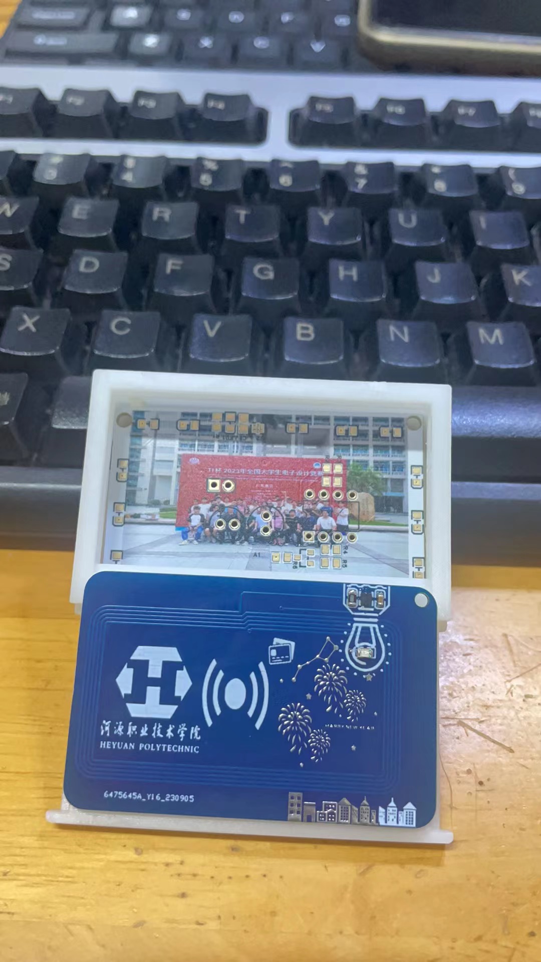
Campus Commemorative PCB
Campus Commemorative Cards
Campus Commemorative Cards
PDF_Campus Commemorative pcb.zip
Altium_Campus Commemorative pcb.zip
PADS_Campus Commemorative pcb.zip
BOM_Campus Commemorative pcb.xlsx
96982
Building a minimal flight controller using Arduino and MPU6050 (with example programs)
It includes a power distribution board; simply plug in the MPU6050 and Arduino Ano to use it.
The link https://www.bilibili.com/read/cv27782906/
includes a power distribution board; simply plug in the MPU6050 and Arduino ANO to use it. It features one IIC (MPU6050) input pin, one analog input pin (for connecting an angle-of-attack sensor), and three PWM input pins (receiver channels 1, 2, and 4 for pitch, roll, and yaw). It also has four output pins for supplying PWM to the servos (canards, ailerons, and rudder). The servo and Arduino power supplies are independent, with two power ports: 7-12V for the Arduino and 5V for the servos.
aoasensor.stl
aoa_ctrl_and_yaw_damper_MPU6050_final_PD.ino
e63d0bff918738991de3f9fce6688915352485377.png
PDF_Arduino and MPU6050 Simple Flight Controller Creation (with Example Programs).zip
Altium_arduino and MPU6050 Simple Flight Controller Creation (with Example Programs).zip
PADS_arduino and MPU6050 Simple Flight Controller Creation (with Example Programs).zip
Creating a Simple Flight Controller with BOM_arduino and MPU6050 (with Example Programs).xlsx
96983
Breathing Photo Ambient Light Ornament
This project is divided into two main categories:
1. A breathing ambient light composed of an NE555 timing chip, LED lights, and some peripheral circuits;
2. In addition, an NFC communication system composed of an NXP radio frequency chip and peripheral circuits is used to enable sharing of photos and data with a mobile phone.
PDF_Breathing Photo Ambient Light Ornament.zip
Altium_Breathing Photo Ambient Light Ornament.zip
PADS_Breathing Photo Ambient Light Ornament.zip
BOM_Breathing Photo Ambient Light Ornament.xlsx
96984
Jlink-SWD isolation
Whenever I'm troubleshooting the motor, the high voltage and interference always make me anxious. After all, that's how I ruined two USB ports on my computer. And that's how I started having this problem.
Adapted from: https://oshwhub.com/yuyunlin/h7tool-swd-ge-li

3.3V debugger input
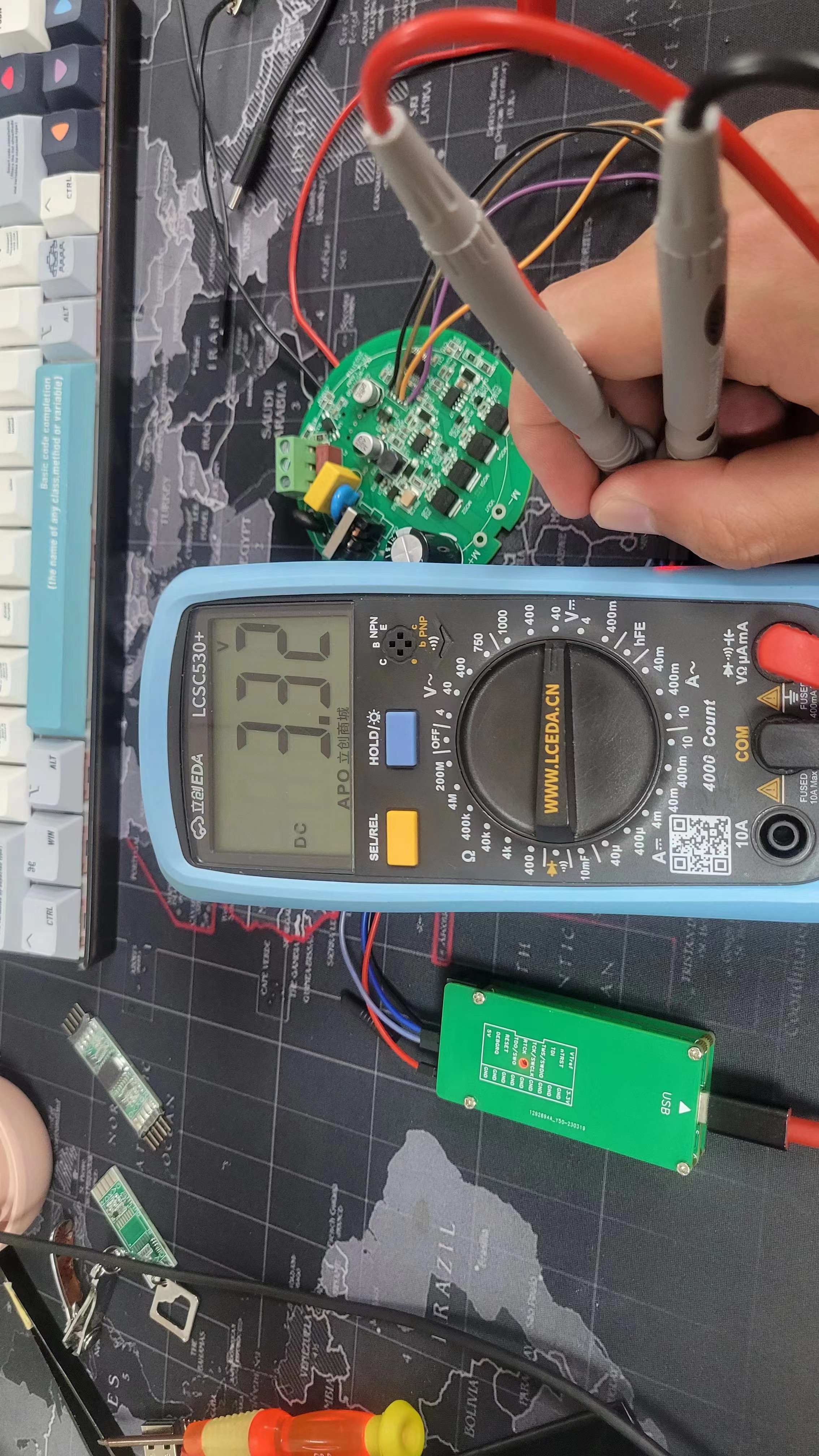
5V MCU device

download
J-Link v9 normal debugging download 5V MCU (Lingou)
QQ20231123-11530.mp4
PDF_Jlink-SWD Isolation.zip
Altium_Jlink-SWD Isolation.zip
PADS_Jlink-SWD Isolation.zip
96987
electronic
 3. ST7789 color screen driver board;
 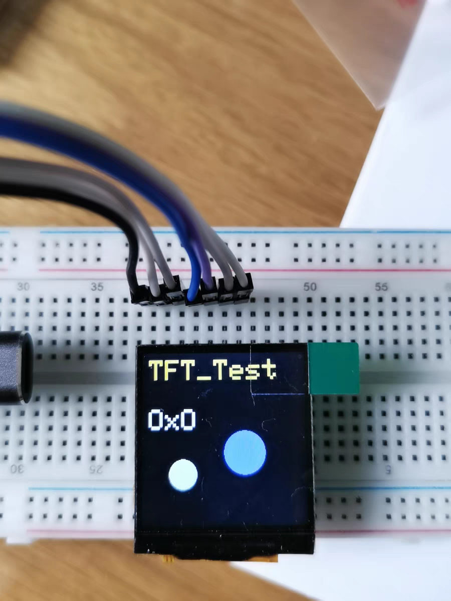 4. LCD12864 driver board.
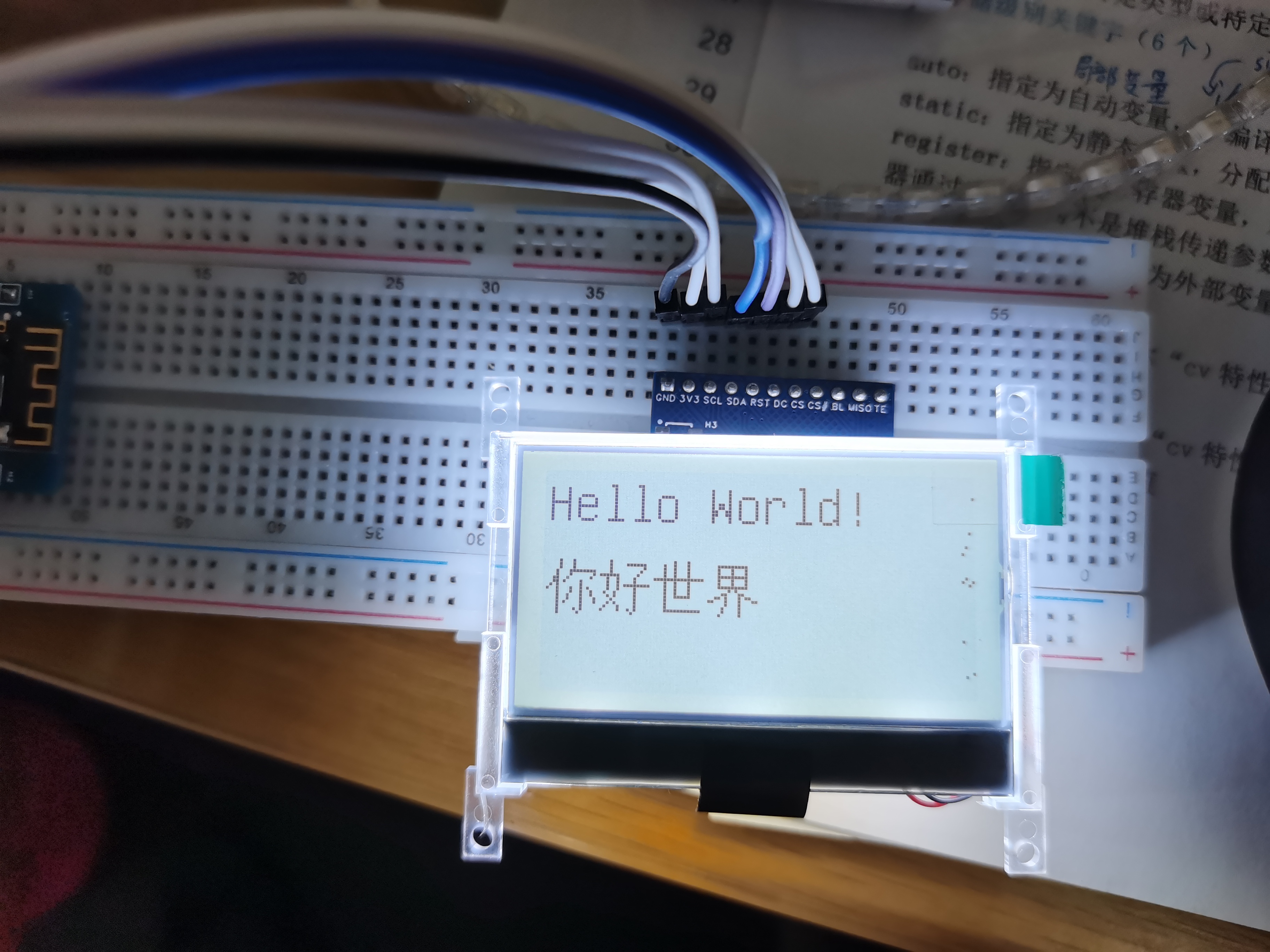


 京公网安备 11010802033920号

 5082-7408-HC000


