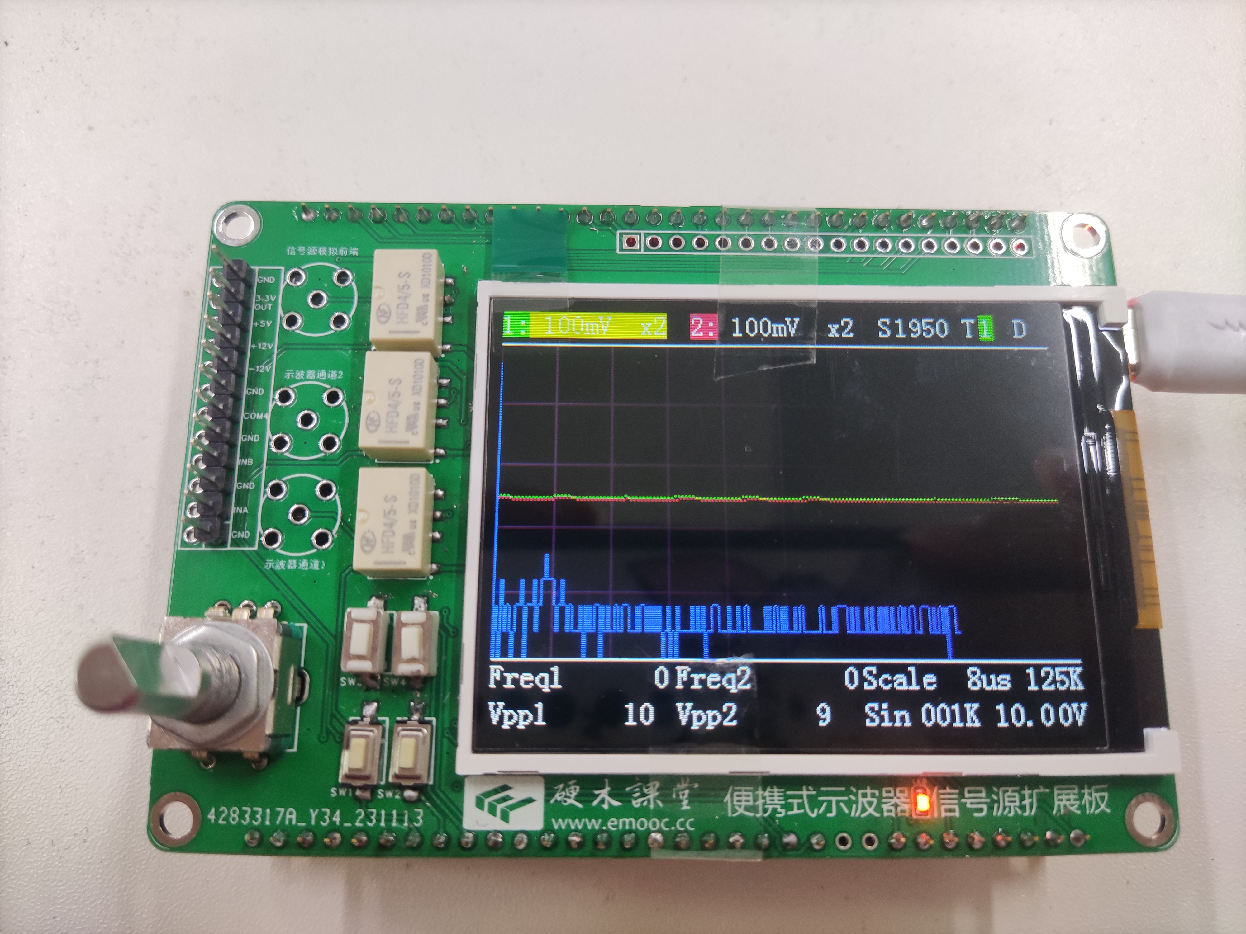
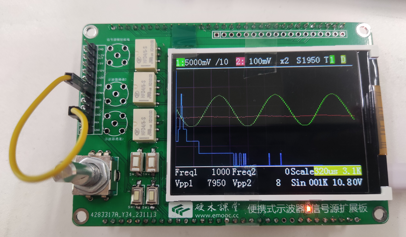
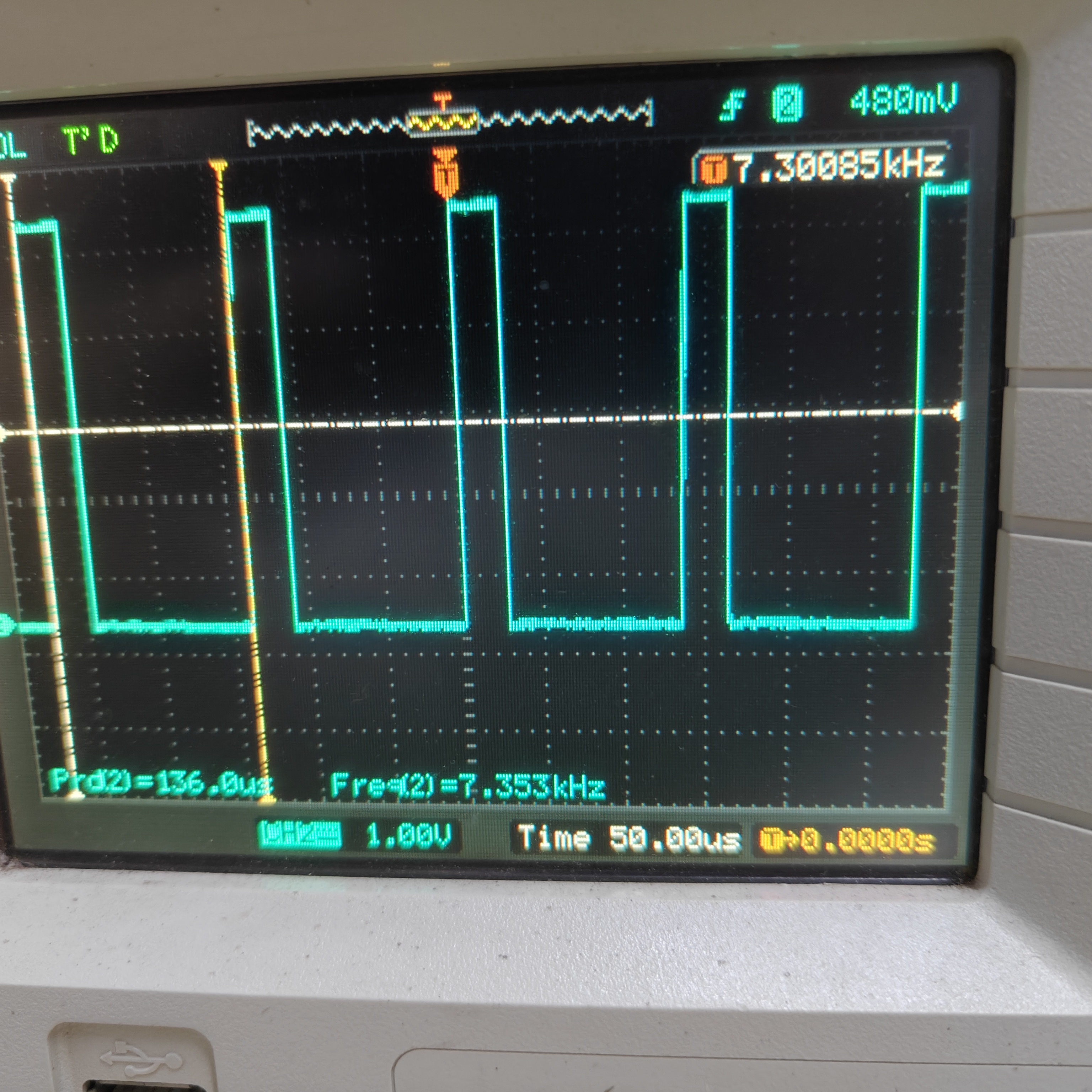
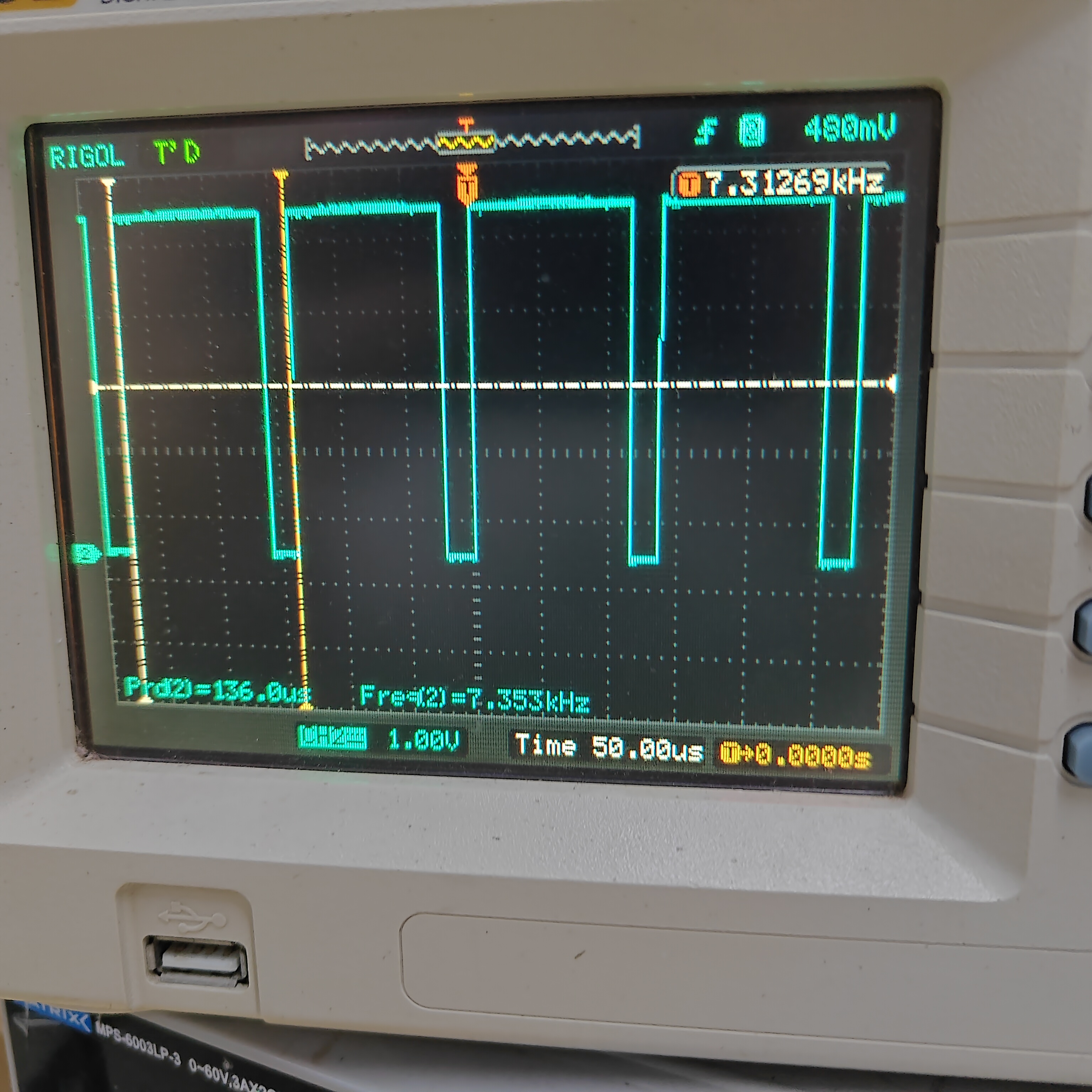
Result Diagram:
Implementation of Signal Conditioning Circuit:
Below, we will briefly introduce the analog input and output channels on the AFE03 board. We will then discuss the design and calculation methods in detail later.
Analog Input Channel Introduction:
This includes signal conditioning implemented with resistor voltage dividers and operational amplifiers, and a square wave output implemented with a comparator (for triggering and frequency measurement).

INA, INB: The input terminals of the oscilloscope. The pocket instrument sends an analog signal to this point. Here, a 1MΩ input impedance is achieved through a series resistor voltage divider, generating two signals for selection: one is a direct input, and the other is attenuated to 1/20.

gain: A selection switch that selects either the direct signal or the signal attenuated to 1/20 to enter the first-stage non-inverting amplifier. The non-inverting amplifier performs two tasks: first, it amplifies the input signal at the non-inverting terminal by a factor of two; second, it shifts the amplified signal by 1.65V, calculated as Vo = 1.65 + 2*Vi. Therefore, the overall gain of the corresponding circuit is either 2 times or 1/10 times.
AnalogA and AnalogB: The analog signals, amplified and shifted by the inverting amplifier, are connected to the STM32H750 development board and enter the H750's ADC.

TrigerA and TrigerB: The square wave signal generated by AnalogA, AnalogB, and the DC reference level (generated by one of the H750's DACs) after passing through a comparator enters the STM32H750's timer for frequency measurement.
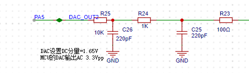
DAC_OUT2: The DC reference level is output through the STM32H750's internal DAC2 configuration.
Analog output channel description:
Includes signal conditioning implemented by resistor dividers and operational amplifiers, and a square wave output implemented by a comparator (for triggering and frequency measurement).
The STM32H750's DAC1 output has a waveform range of 0-3.3V.
A second-order RC filter implements a low-pass filter function.

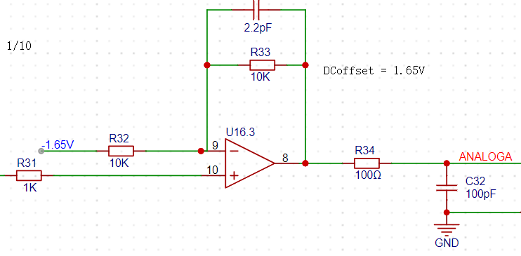
A resistor divider and buffer convert the 5V input to a low-impedance 2V output, which is then amplified by -5 times for shifting the output signal.
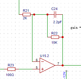
The output amplifier performs two functions: first, it amplifies the non-inverting input by 6 times; second, it shifts the amplified signal by -10V before outputting it. The calculation formula is Vo = -10 + 6 * Vi.

The voltage divider network is used to achieve good results when outputting small signals by utilizing analog circuit voltage division.
Below, we will introduce the calculation of the analog circuit in detail:
Analog Input Channel Calculation:
This section requires some basic knowledge of operational amplifiers.
First, we need to understand that when the VREF of the STM32H750 is powered by 3.3V, the input range of the STM32's ADC is 0-3.3V, while our maximum input signal is ±15V. Therefore, we need to solve the problem of large signal input not saturating. Let's solve an equation:
15 * a + b = 3.3
- 15 * a + b = 0,
which gives a = 0.11 and b = 1.65.
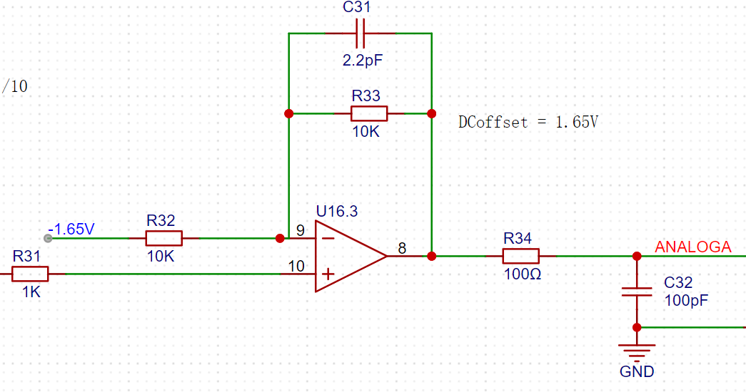
This means we need to attenuate the input signal to at least 0.11 times (approximately 1/9), and then add 1.65V DC to meet the full-scale input of the ADC. Therefore, we use the following operational amplifier circuit. The resistor network achieves 1/20 attenuation, and the operational amplifier performs a 2x amplification and a 1.65V voltage shift, thus achieving 0.1INB + 1.65V.
We can use the superposition theorem to analyze this circuit. First, when analyzing the contribution of the input signal INB to the output Vo, we ground the other voltage source in the circuit, -1.65V. This way, the input signal is divided to 1/20 after passing through R14 and R18, and then amplified by a factor of 2 by the non-inverting amplifier circuit. The overall gain of the input signal is 1/10. When analyzing the contribution of -1.65V to the output, we ground the input signal AIN, and the amplification factor of -1.65V is -1. Therefore, we obtain the output Vo = -1.65V * (-1) + AIN/10 = 1.65V + AIN/10.
The -1.65V above is obtained from -12V through a resistor divider and buffer.

This circuit solves the problem of matching the ±15V input to the ADC's 0-3.3V input range. We also need to consider accurate sampling even with small input signals. For example, a 10mV signal will attenuate to 1mV after passing through this circuit. To maximize the signal-to-noise ratio of the input signal, we add a switching mode to the analog front-end. When acquiring small signals, the switch selects the direct input of INB to the non-inverting input of the op-amp, instead of selecting the attenuated signal from INB. This ensures the signal entering the ADC is as large as possible. Combined with a 16-bit ADC, this ensures accurate and reliable sampling results.
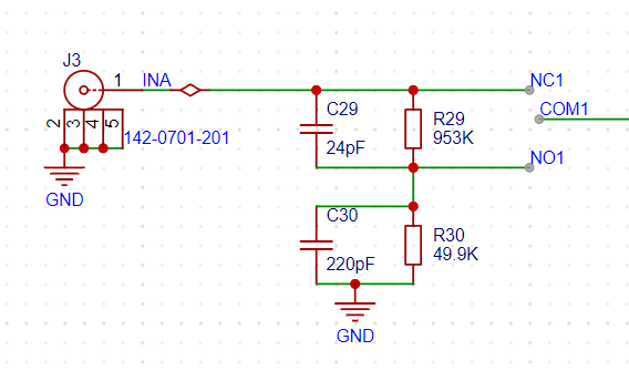
As shown in the diagram, we add a signal switch (relay or manual switch) after the 1M ohm input voltage divider resistor to select whether INB enters the op-amp's non-inverting input directly or after being divided by 1/20. Both methods result in a 1M ohm input impedance for INB. When we need to acquire small signals, we can toggle the switch to use the direct input for more accurate measurement results.
We can calculate that when the direct input is selected, Vo = 2AIN + 1.65, and when the attenuation input is selected, Vo = AIN/10 + 1.65.
Analog output channel calculation:
When the VREF of the STM32H750 is powered by 3.3V, the output range of the internal DAC is 0-3.3V. To achieve the ±10V output required in the problem, we need to solve the following equations:
0*a + b = -10V
3.3*a + b =
Solving for 10V , we get a=6.06 and b=-10
, which allows us to design the following circuit:
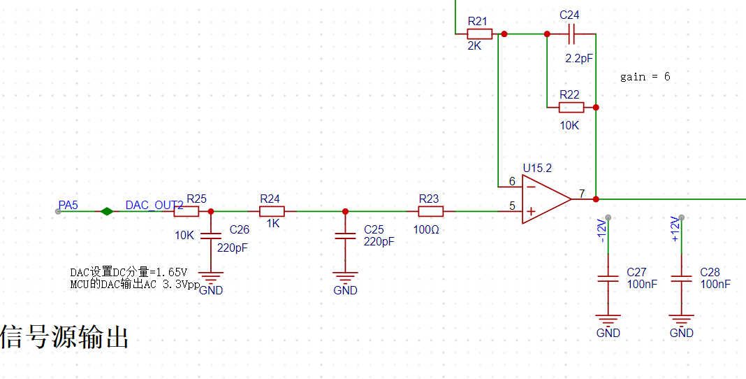
In the diagram above, the 0-3.3V signal output from the STM32H750's internal DAC is filtered by a low-pass filter and then input to the non-inverting input of the TL082, forming a non-inverting amplifier with a gain of 6. The amplified waveform is 0-19.8V. Then, utilizing the -5x amplification capability of the TL082's inverting amplifier section, the +2V obtained from the 5V voltage divider is amplified by -5x to obtain -10V. This -10V is then superimposed on the 0-19.8V signal output from the non-inverting amplifier to obtain an output of approximately ±10V. The calculation formula is: Vout = 6*Vin -10.
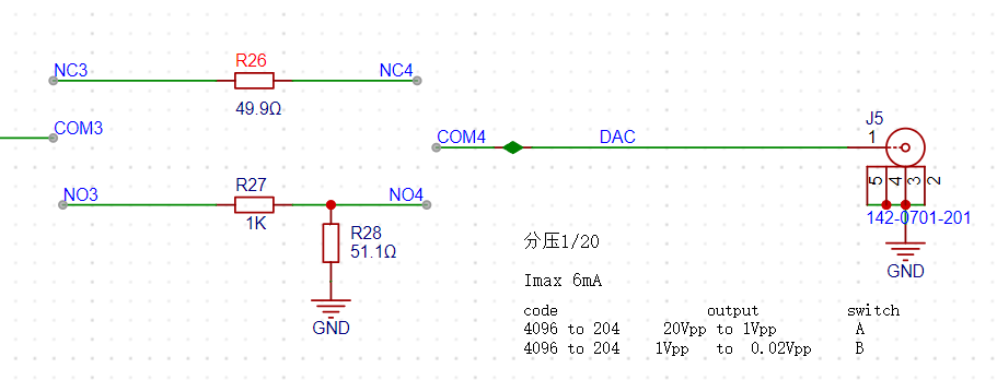
Similar to an ADC, to ensure the signal source output covers ±10mV to ±10V, while simultaneously balancing a large signal range and small signal accuracy, the DAC's resolution is a crucial factor. The H750's DAC is 12-bit, and its full-scale output (using all 4096 code values) is ±10V. When outputting small signals by reducing the DAC code value, to achieve a 7-bit voltage resolution (128 vertical points), the waveform must be attenuated by 128/4096 = 1/32. This translates to an output voltage range of ±10V/32 = ±0.3215V. For signals smaller than ±0.3125V, further reducing the code value results in insufficient DAC resolution and noticeable waveform steps. Therefore, we use analog voltage division. When outputting signals smaller than ±0.3125V, we use a switching resistor divider to attenuate the waveform by 1/20, ensuring sufficient voltage resolution for small signals. Simultaneously, the combination of R57 and R62 ensures a 50Ω output resistance at 1/20 attenuation, and R5 ensures a 50Ω output resistance at x1.
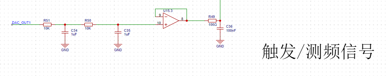
Comparator circuit:
To implement the trigger and frequency counter functions, we designed two comparator channels on the board. These channels convert the waveforms of the two analog input channels before they enter the ADC into square wave signals for use as timer inputs in the H750. The reason for using the waveforms before entering the ADC for comparison is that the waveforms entering the ADC, after conditioning by the front-end analog circuitry, fall within the known 0-3.3V range, making the comparator's comparison threshold easier to design.

As shown in the diagram above, the H750 uses its internal DAC2 to output a 0-3.3V DC signal to compare with the waveform of channel 2 before entering the ADC, converting the channel 2 waveform into a square wave. This allows the H750's timer function to use the square wave signal for interrupt handling and timer capture.
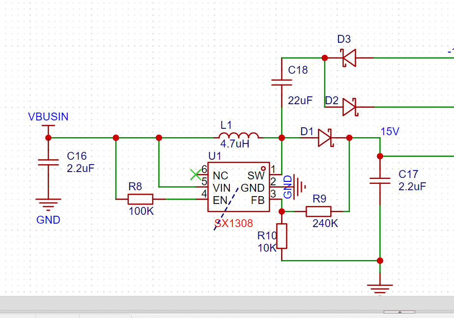
The boost module uses an SX1308 to boost to 15V; the positions of R9 and R10 must be correctly matched! The -15V generation utilizes capacitor reverse vibration and diodes.
Ideal board color in mind:

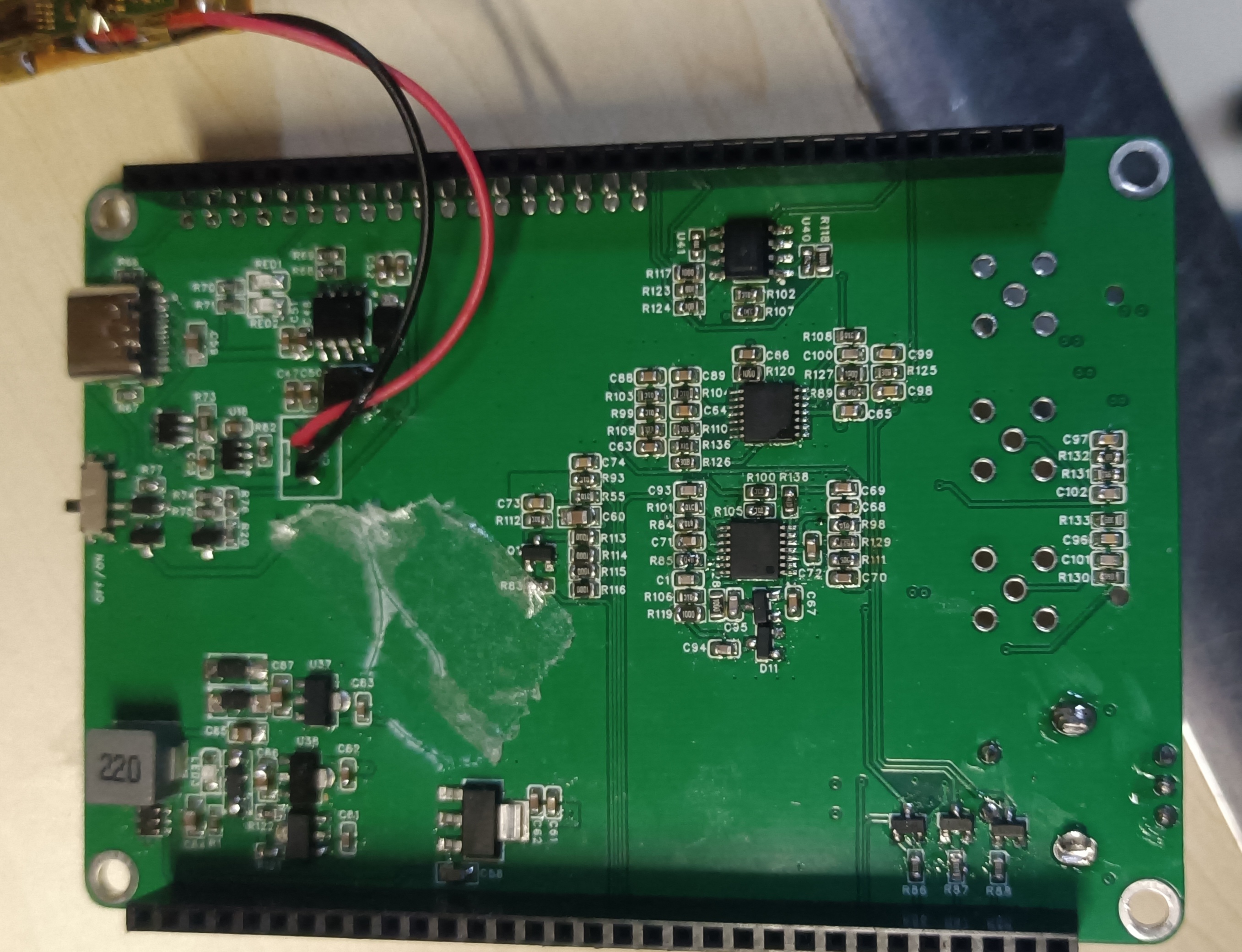
Final physical image:
DAC.zip
Oscilloscope demonstration video 1.mp4
PDF_Based on_Hardwood Classroom_AFE03 Simple Oscilloscope Signal Source Expansion Board.zip
Altium_Based on_HardwoodClassroom_AFE03 Simple Oscilloscope Signal Source Expansion Board.zip
PADS_Based on_Hardwood Classroom_AFE03 Simple Oscilloscope Signal Source Expansion Board.zip
BOM_Based on_Hardwood Classroom_AFE03 Simple Oscilloscope Signal Source Expansion Board.xlsx
97011
ADC-PWM module with motor speed control or LED dimming
The output PWM duty cycle can be adjusted from 0 to 100 via a potentiometer. It can be connected to a motor speed controller or an LED dimming controller, with a fixed output frequency of 7-8kHz.
This is a small toy with a very simple circuit. I haven't touched a 51 microcontroller in a long time; I bought quite a few 51s and STM8s that have been gathering dust. I made a small tool to use them.
The microcontroller reads the I/O port voltage via ADC, converts the voltage into a PWM output with a fixed duty cycle to drive a MOSFET. The recommended operating voltage is 6.5V-20V (maximum 35V; LDOs seem to be 35V, be aware of high voltage difference causing overheating).
You can choose a suitable MOSFET; this one can withstand up to 60V, but it's unnecessary to use such a high voltage. This one was chosen mainly because it's cheap, costing around 30 cents. If you have the resources, you can use an easier-to-drive one.
Considering the microcontroller's driving capability isn't very good, the output frequency is set relatively low to reduce switching losses, but you definitely won't see flickering when driving LEDs.
Note: There is no reverse connection protection; pay attention to polarity.

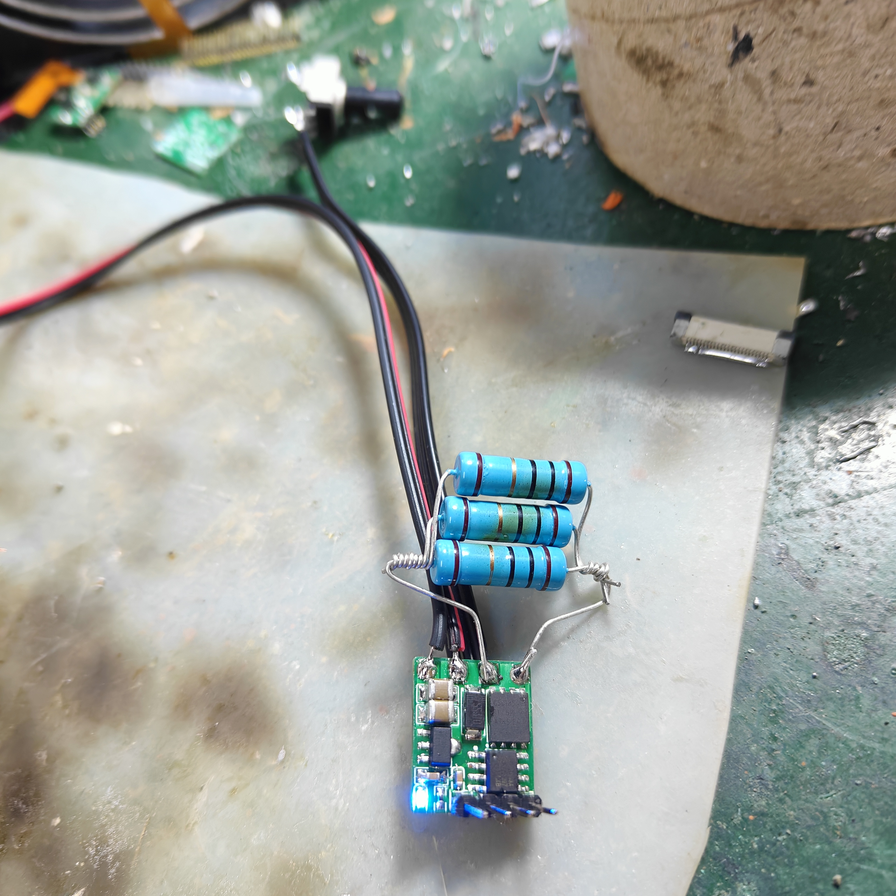
The output was tested using three 10R 3W metal film resistors connected in parallel, equivalent to 3.3R. With a 12V power supply and a duty cycle set to around 60%, the board did not overheat. Currently, I don't have a motor on hand. If you have LEDs, I recommend connecting a small resistor in series.

Adjust the PWM

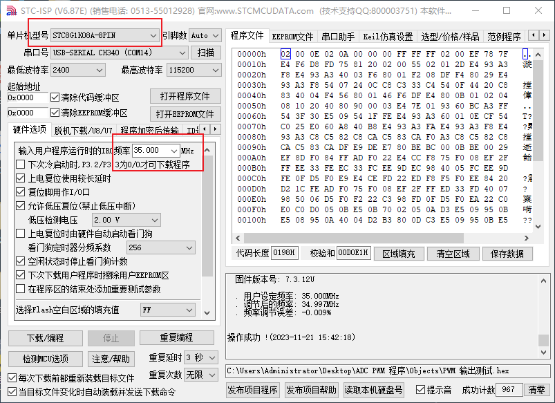
using a potentiometer. ... For programming, use STC_ISP. Download link: https://download.ihsdus.cn/down/2022down/1/21/TCICP.rar?timestamp=655c6678&auth_key=1d8fd78df58a3b8e9e9f7be34fc1ff5a
After opening, please set the parameters as shown in the image. You can then use any serial port programming tool to program it.
To program the circuit board, connect the DuPont wires to +5V GND RXD TXD. Configure the serial port as shown in the image, paying attention to the selected options. Refer to the tutorial: https://zhuanlan.zhihu.com/p/593000651.
Finally, connect the wires according to the silkscreen markings on the board.
PWM output test.hex
ADC PWM program.zip
PDF_ADC-PWM module with motor speed control or LED dimming.zip
Altium_ADC-PWM module with motor speed control or LED dimming.zip
PADS_ADC-PWM module with motor speed control or LED dimming.zip
BOM_ADC-PWM module, with motor speed control or LED dimming.xlsx
97012
Wireless charging based on IP6826
A wireless charger based on IP6826, beautifying your charger with colorful silkscreen printing.
Wireless charging case v1.5.3mf
PDF_Wireless Charging Based on IP6826.zip
Altium_IP6826-based wireless charging.zip
PADS_Wireless Charging Based on IP6826.zip
BOM_Wireless Charging Based on IP6826.xlsx
97013
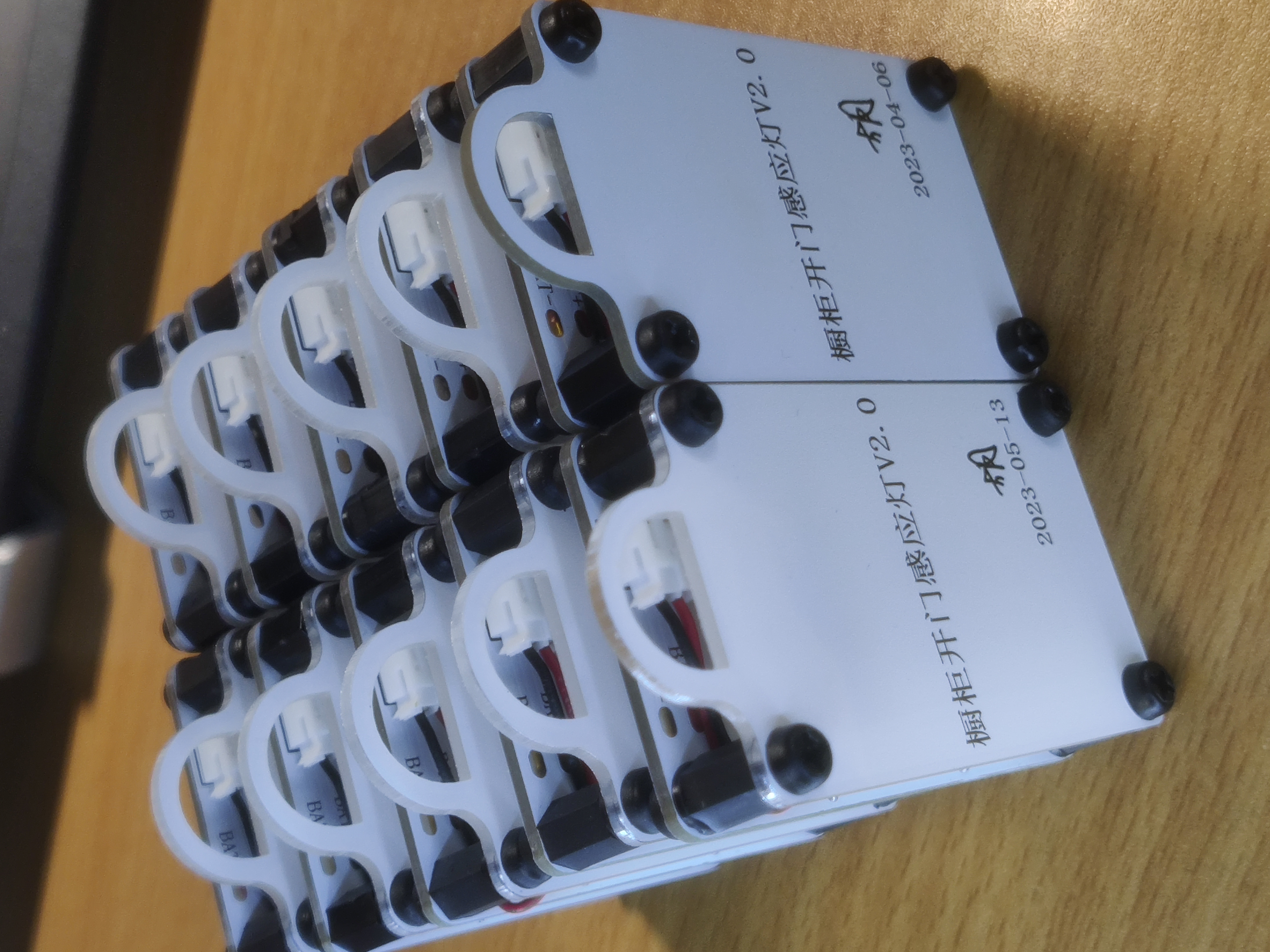
Cabinet door sensor light
The purely analog circuit enables automatic light activation when the door is opened. It is battery powered and has a standby power consumption as low as 15 microamps.
Bilibili video link: Click to play:
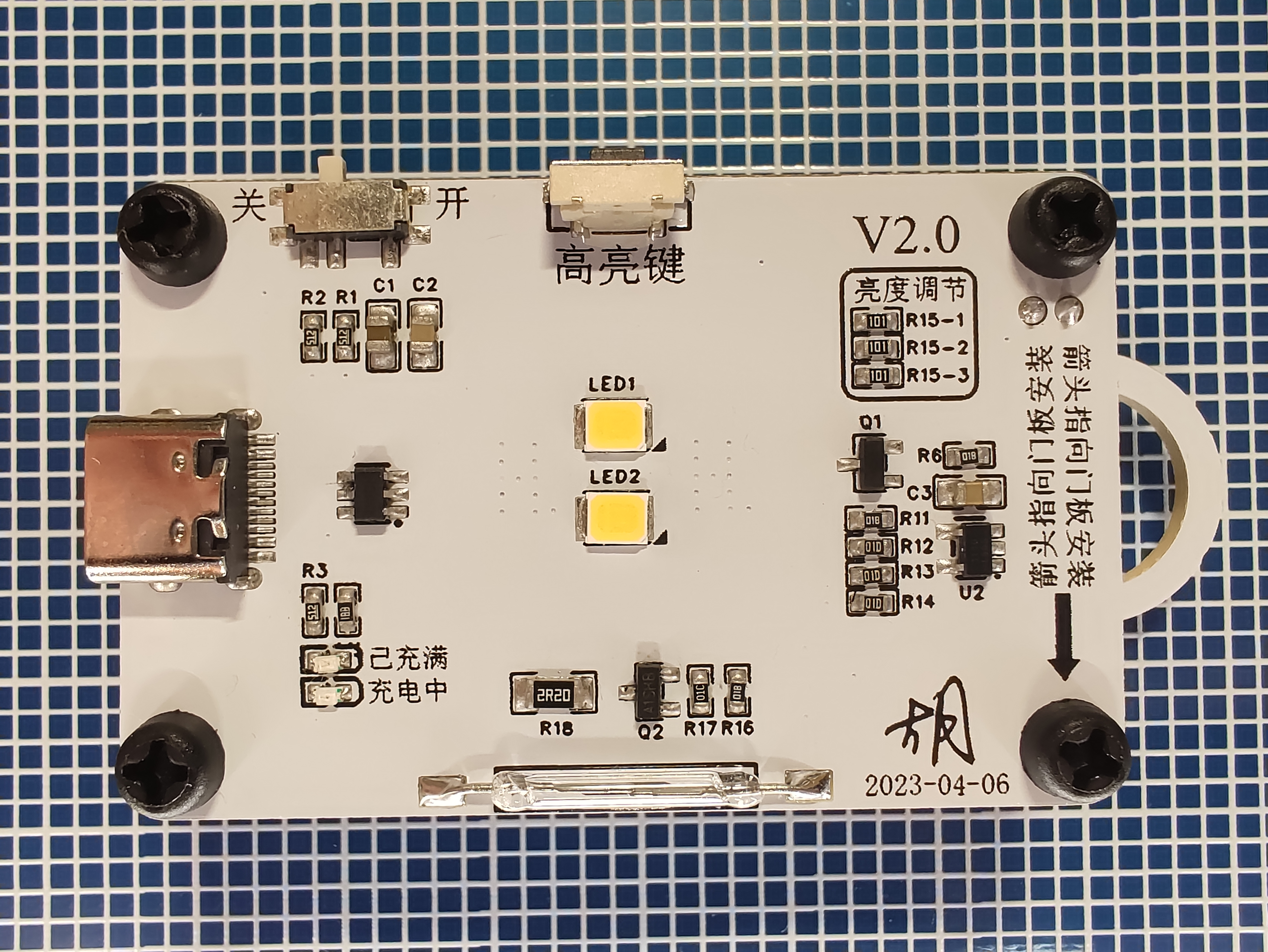
Finished product image of cabinet door sensor light:
Function introduction:
1. Automatic light turns on when the door is opened, no additional operation required;
2. Comprehensive battery protection system, with protection circuits for both charging and discharging;
3. Equipped with a charging indicator light, automatically stops charging and turns on when fully charged;
4. Standby power consumption as low as 15 microamps, consuming only 1000 mAh of power over 7 years of standby;
5. Versatile installation method, can be removed at any time and used as a small flashlight;
6. Equipped with a high-brightness button, pressing it will activate the LED at full load, which can be used in conjunction with flashlight mode;
7. Type-C charging interface with CC resistor, supports C to C cable.
Working principle:
The LED driving part of this product uses analog circuits, only the charging and discharging protection uses a ready-made protection chip.
1. Chip Section:
1-1. The charging protection chip is model TP4059, with a maximum programmable charging current of 600mA. R4 is the current programming resistor. The current relationship table is as follows:

1-2. The discharging protection chip is model DW02A. This chip also includes charging protection. Combined with the battery's built-in protection board, it provides triple charging protection and double discharging protection, ensuring your safety.
2. Analog Circuit Section:
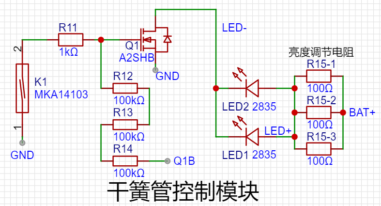
2-1. The main LED bead driving section uses only one N-channel MOSFET. The principle is based on voltage division through the gate resistor. When the reed switch is closed due to the door being closed, the gate is pulled low through R11, the MOSFET is cut off, and the LED is off. When the door is opened, the reed switch is open, the gate is pulled high by R12, R13, and R14, the MOSFET conducts, and the LED lights up. R14 connects to Q1B, which is the middle pin of the switch. The switch controls whether Q1B is high or low. If Q1B is low, whether the door is open or not will not affect the LED bead's off state.
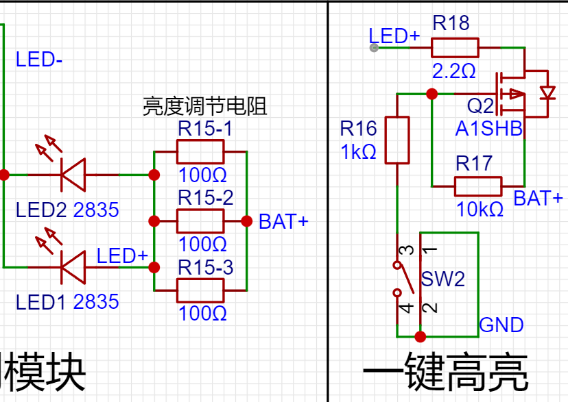
2-2. The working principle of the high-brightness button is to use a very small current-limiting resistor R18, connected in parallel with three larger fixed current-limiting resistors R15-1, R15-2, and R15-3, to make the LED work at full load.
2-3. When the door is closed, the reed switch closes. At this time, R11, R12, R13, and R14 are directly connected in series across the power supply. This is why R12, R13, and R14 have such large values. The current at this time is
3.7 ÷ (100000 + 100000 + 100000 + 1000) = 0.0000122 amps, which is equivalent to 12 microamps. Adding the standby power consumption of the two chips, the actual measured standby current of the entire device is only 15 microamps, which is extremely low power consumption. It only consumes 1000 mAh of power in 7 years of standby.
Minor details & precautions for replication:
1. This open-source project contains two versions; please replicate V2.0. V1.0 was a design failure, but because of the effort I put into it, I couldn't bear to delete it, so I'm keeping it here as a memento.
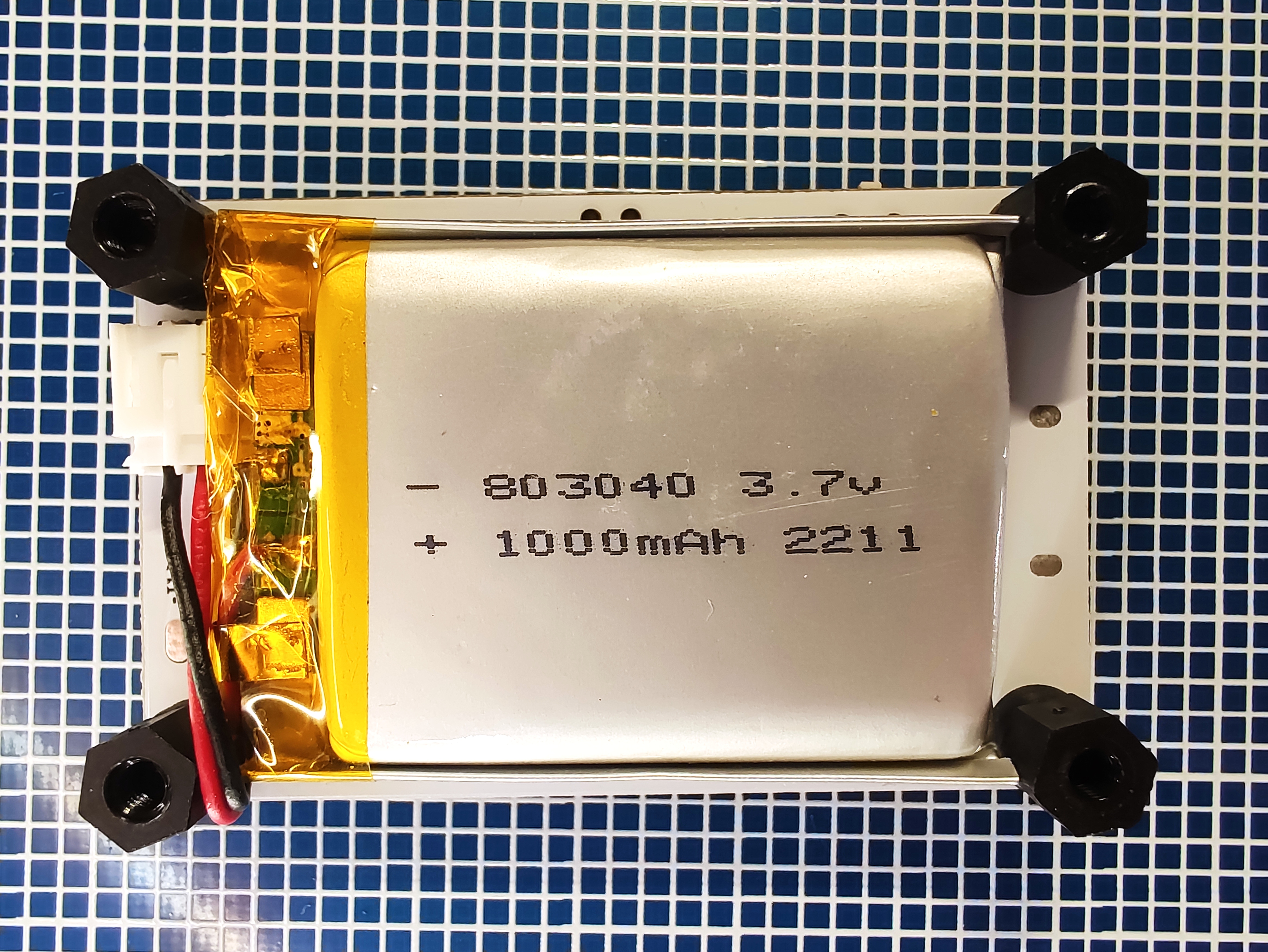
2. Version V2.0 is compatible with battery model 803040, using PH2.0 terminals for connection. It also has lead-out pads for wire connection.
3. Regarding the backplate, this open-source project offers two material options: PCB and acrylic. Acrylic is recommended as it's lighter, more dimensionally accurate, and has a more perfect appearance.
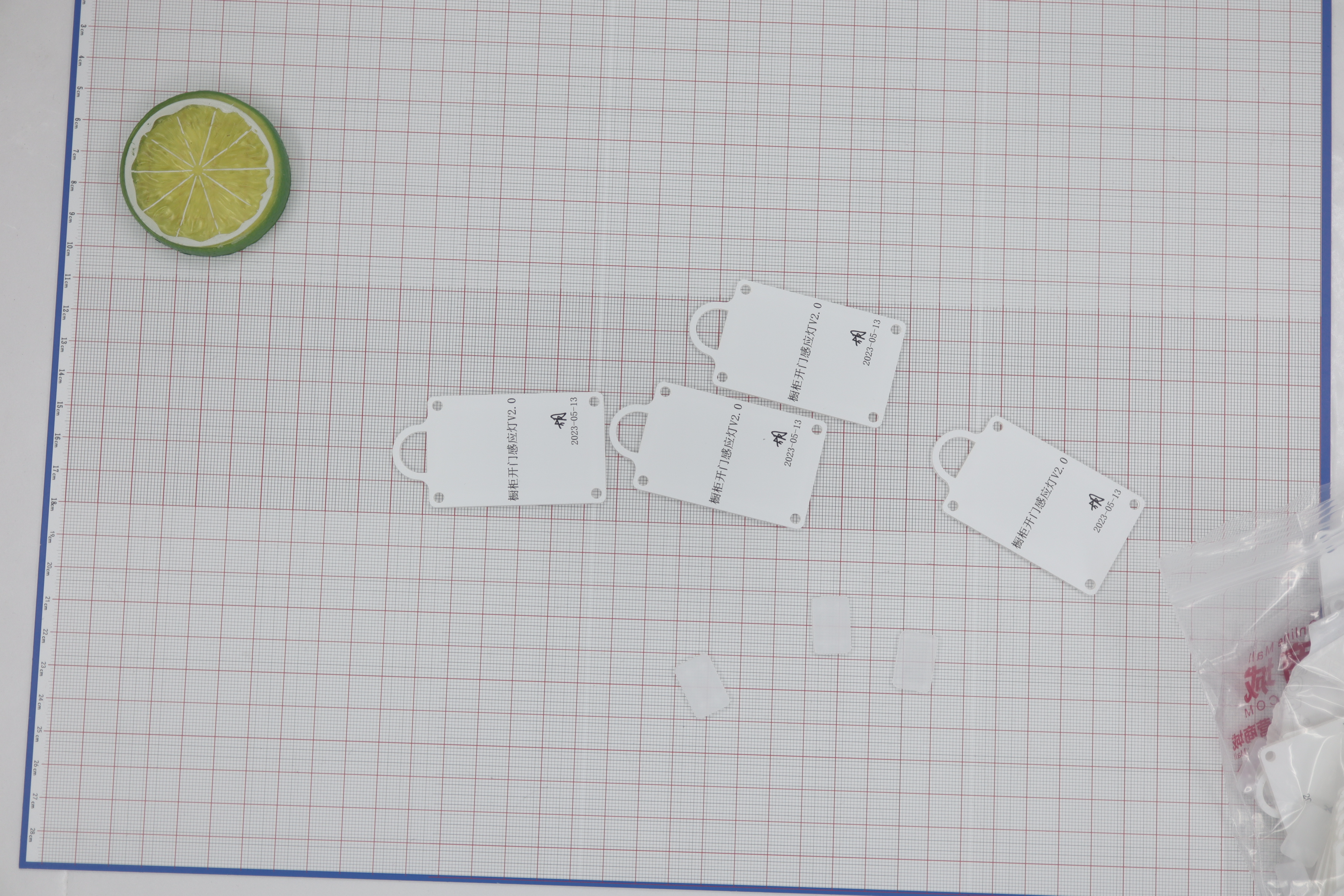
4. The open-source panel design includes the LED diffuser plate (the small, semi-transparent cube), which is not recommended. While it softens the light, it also reduces the illumination angle, creating noticeable dark corners when placed in cabinets.
5. Installation methods include hanging, magnetic attachment, adhesive, and various other methods I haven't considered. In short, it's highly versatile. Feel free to use your imagination and discuss in the comments section.
Thank you for watching, and have a wonderful day!
PDF_Cabinet Door Sensor Light.zip
Altium_cabinet door sensor light.zip
PADS_Cabinet Door Sensor Light.zip
97014
WIFI Multi-channel Power Meter (bl0906+esp8266) All-in-one Version
A 6-channel power acquisition module based on bl0906.
Modify the original project to directly integrate the 8266, requiring only one board and making it easier to use for free.
Considering space constraints after integration, replace the power module with a Prida one. Since
I had a Prida 5V module on hand, I added an LDO circuit. If you purchased a 3.3V module, you can remove the LDO section.
Change the voltage transformer divider resistor from 2010 to 0805; testing showed no problems.
You can replace the 8266-12F with a C3-12F for potentially better performance and Bluetooth support. If you're concerned about signal strength, you can add an IPX connector to the C3F to connect an external antenna.
The ESP8266-12F can be replaced with an ESP07s;
the procedure for connecting an external antenna is the same as the original project, but please modify the serial port to tx:5, rx:4.


WeChat_20231124104346.mp4
PDF_WIFI Multi-channel Power Meter (bl0906+esp8266) All-in-One Version.zip
Altium WiFi Multi-channel Power Meter (bl0906+esp8266) All-in-One Version.zip
PADS WIFI Multi-channel Power Meter (bl0906+esp8266) All-in-One Version.zip
BOM_WIFI Multi-channel Power Meter (bl0906+esp8266) Integrated Version.xlsx
97015
Mouse-Serial Port Conversion_CH9350L
Using the CH9350L chip, the single-port version is the host computer, and the dual-port version is the slave computer.
Circuit board purpose: Mouse to serial port, serial port to mouse; allows for processing of intermediate serial port data.
Operating states:
State 2
; Baud rate:
300000
and above. Currently, this circuit board
only has DM and DP ports on the host computer, so there is only one port.
The following is from the official documentation:
Pin Name
State 0/1 (Default)
State 2
State 3
State 4
S0
1
0
1
0
S1
1
1
0
0
Baud Rate
115200 (Default)
57600
38400
300000
BAUD1
1
0
1
0
BAUD0
1
1
0
0
Lower Computer (Default)
Host Computer
SEL
1
0
CH9350DS.PDF
PDF_Mouse-Serial Port Converter_CH9350L.zip
Altium Mouse - Serial Port Converter - CH9350L.zip
PADS_Mouse-Serial Port Converter_CH9350L.zip
BOM_Mouse-Serial Port Conversion_CH9350L.xlsx
97016
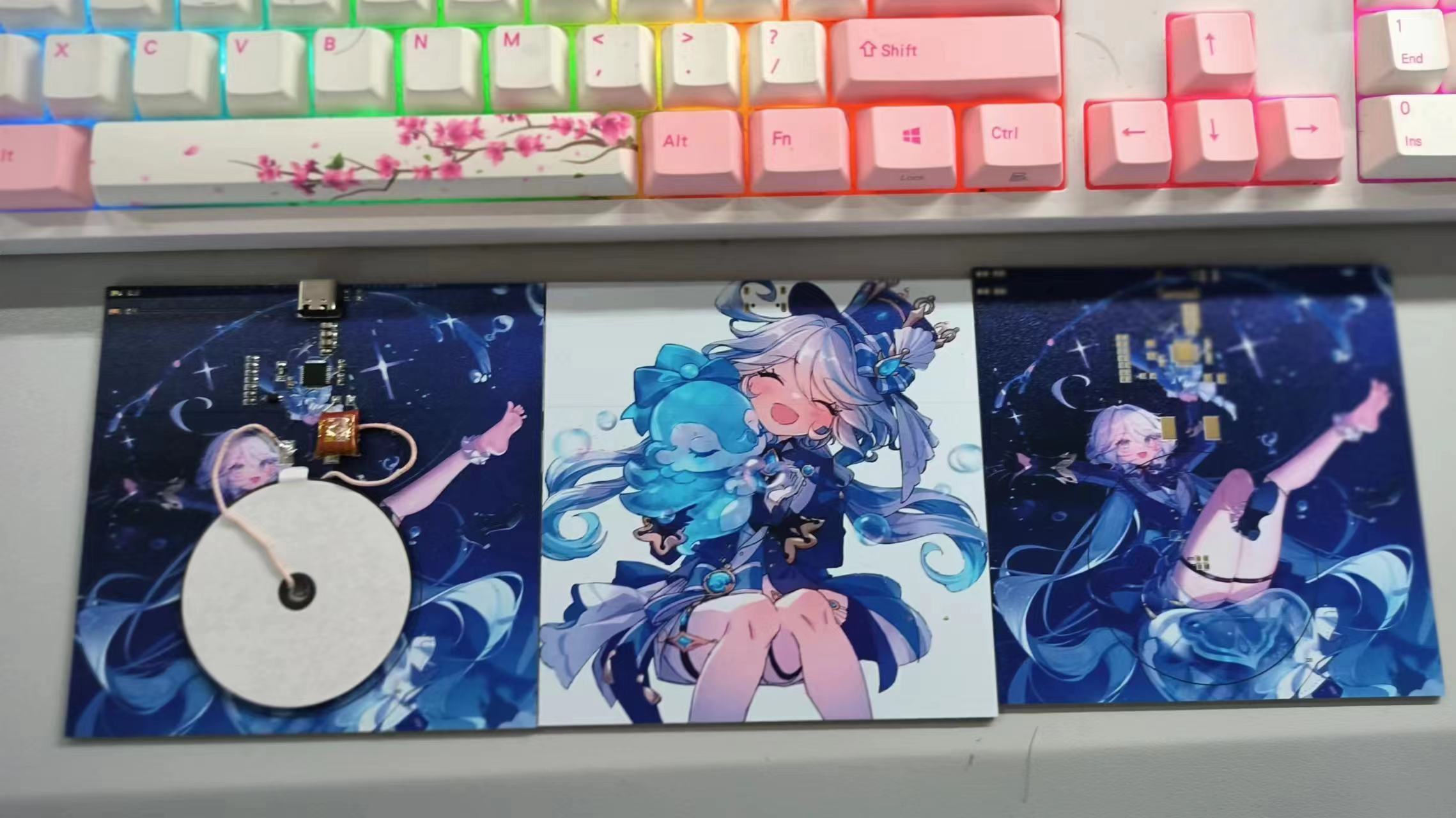
Wireless charging and discharging module
Based on the T3168 and T510 wireless charging and discharging modules, it comes with a coil and has a power of about 2W. It is suitable for modifying headphones, mice, and keyboards for charging. It has few components and can be obtained for free by using the sign-in bonus on Taobao.
Principle:
This design integrates existing coil modules and T3168 and T510 wireless charging/discharging modules, requiring few components and making it suitable for modifying headphones, keyboards, and mice into wireless charging modules.
Additional information:
The schematic diagram cannot be displayed; I have attached the file
but deleted the video file. You can watch it on Bilibili: [T3168 and XKT510 Wireless Charging/Discharging Modules] https://www.bilibili.com/video/BV14w411P7ix/?share_source=copy_web&vd_source=938997900b3c3176b044eaf987fa159f
Wireless charging and discharging module_2023-11-23.epro
PDF_Wireless Charging and Discharging Module.zip
Altium Wireless Charging/Discharging Module.zip
PADS Wireless Charging and Discharging Module.zip
97017
STM32H750 Oscilloscope Portable Expansion Board [Training Camp]
Originating from the EDA Instrumentation Training Camp, this project features waveform measurement and generation functions; it has a built-in battery and integrated charging and discharging protection circuit, making it easy to carry and use; it also has an automatic power switching circuit, supporting both battery power and external power supply.
This project originates from the EDA Instrumentation Training Camp and is a replica of the Hardwood Classroom AFE03 oscilloscope & signal source expansion board. It is designed for use with the Hardwood Classroom STM32H750 core board. I/O allocation is only applicable to the H750 core board; please refer to the schematic,
expansion board image, finished
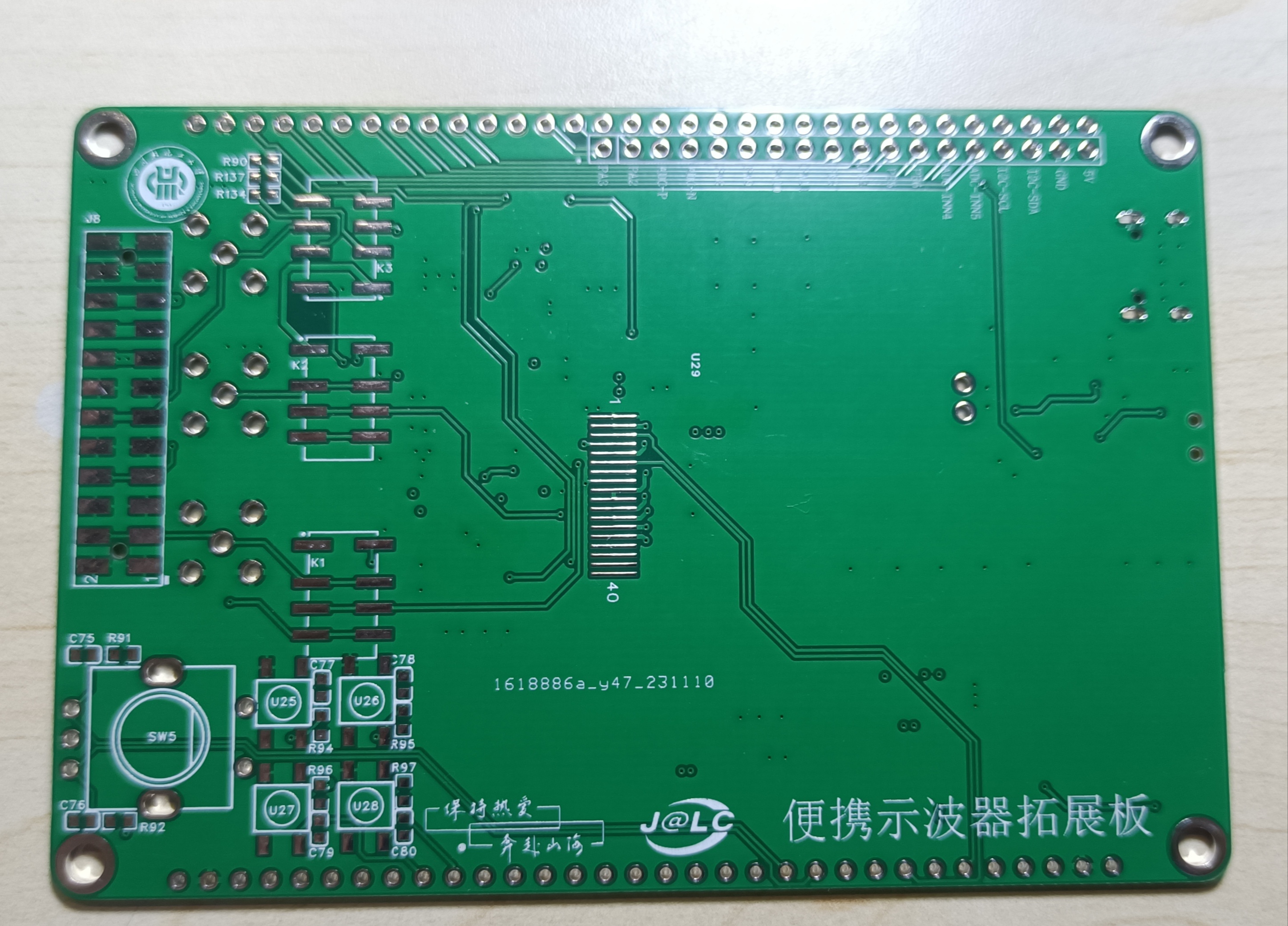
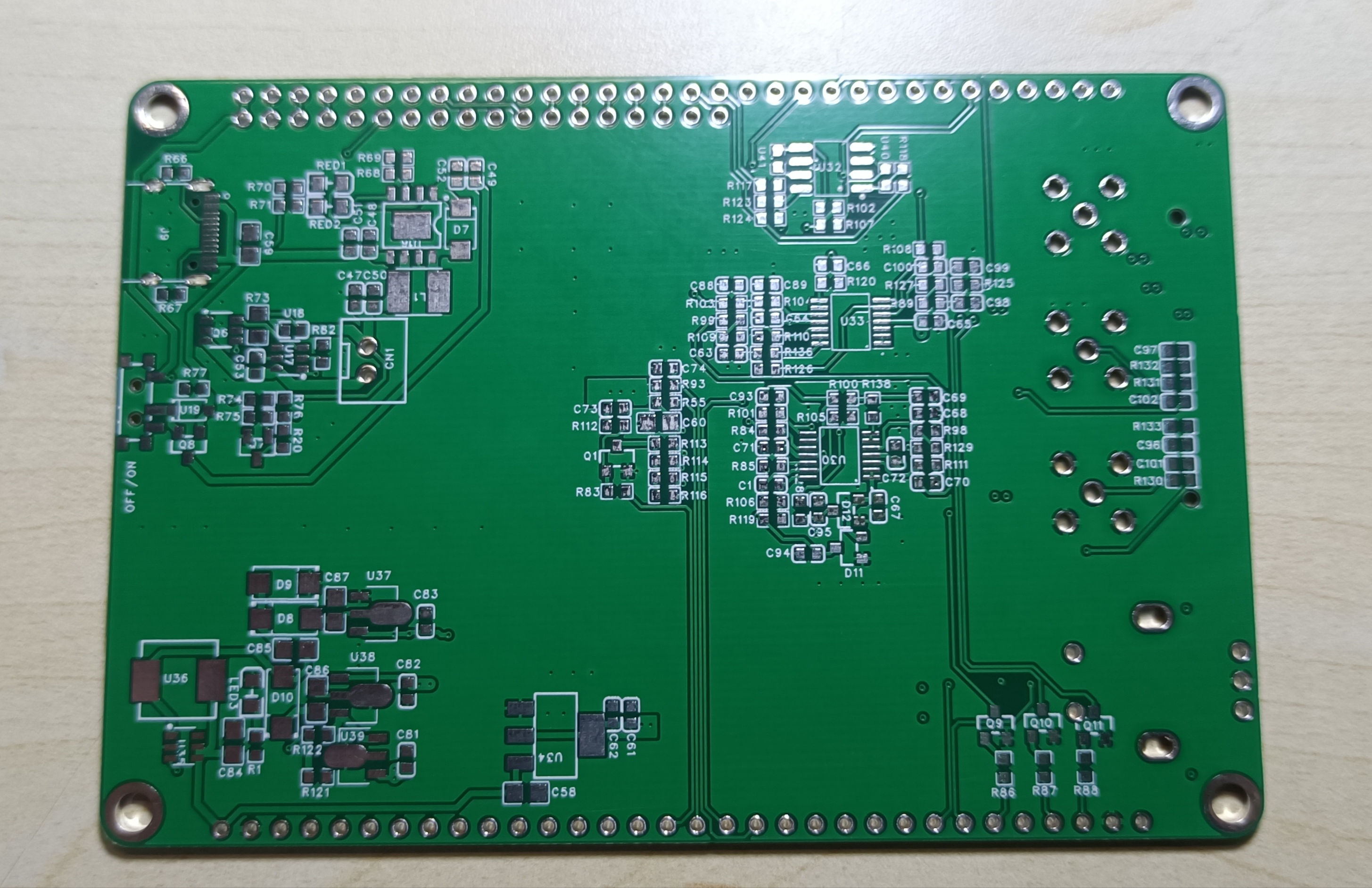

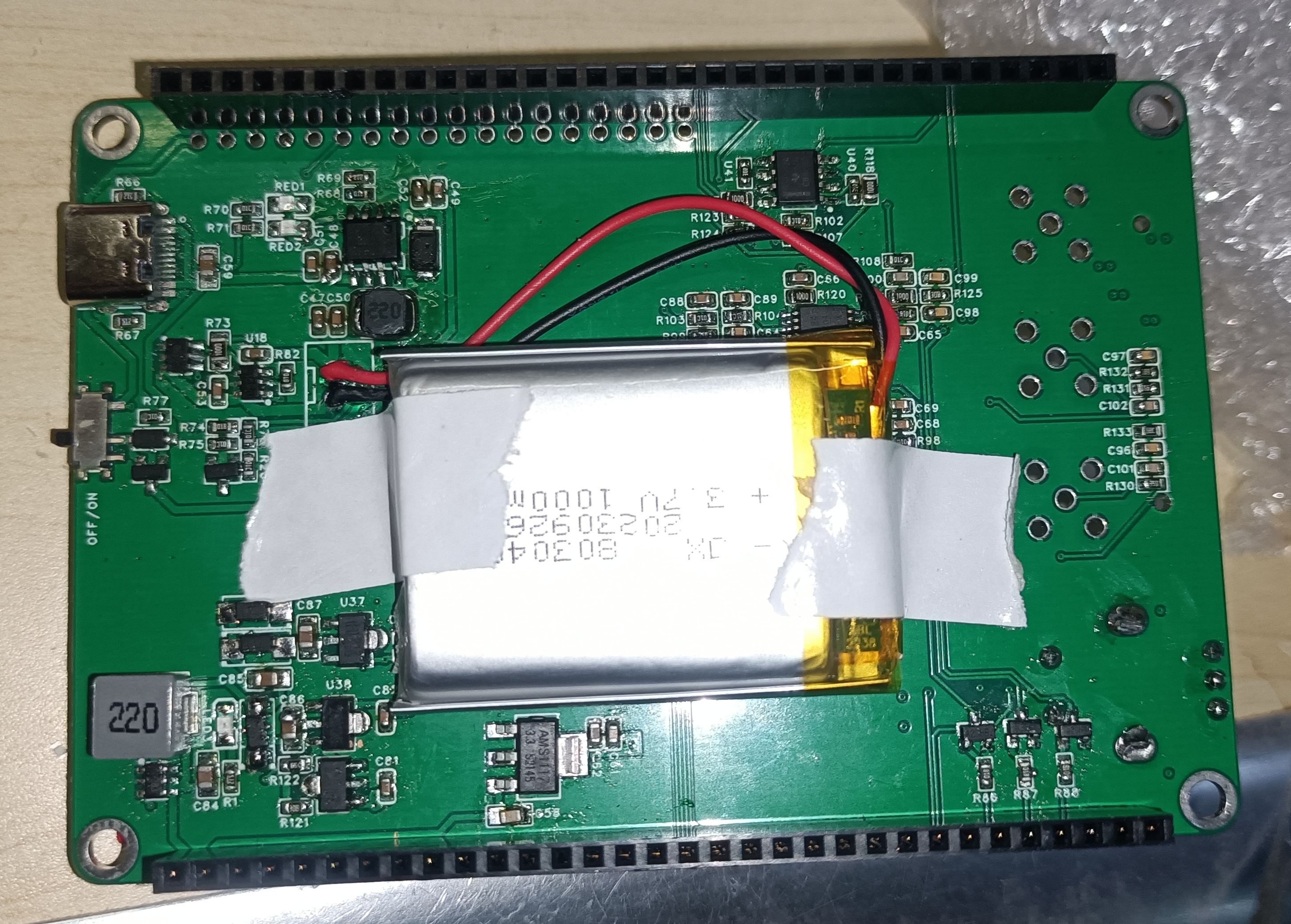
product waveform diagram, and testing details for
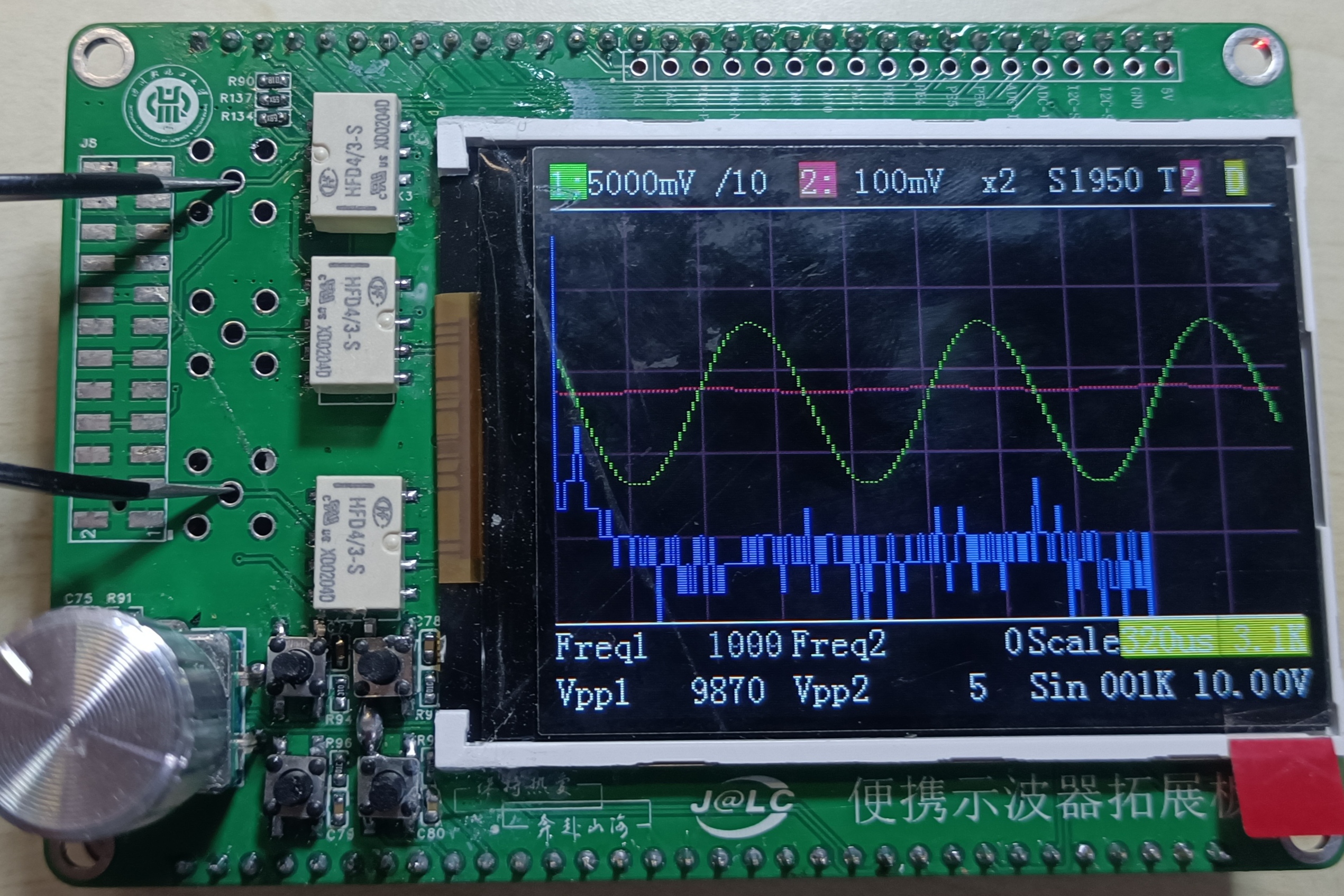
the replica section
. The replica section also references the official documentation, which can be found at the following link:
This project replicates the Hardwood Classroom AFE03 oscilloscope & expansion board. The hardware design and code are available on the LCSC open-source platform. Detailed explanation of oscilloscope code creation from the Hardwood Classroom Knowledge Base:
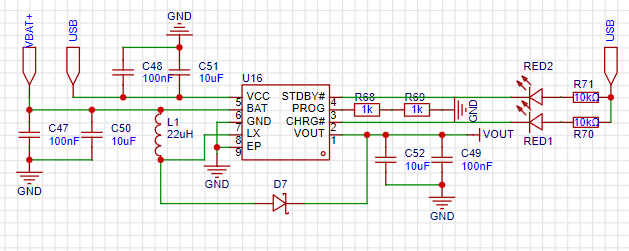
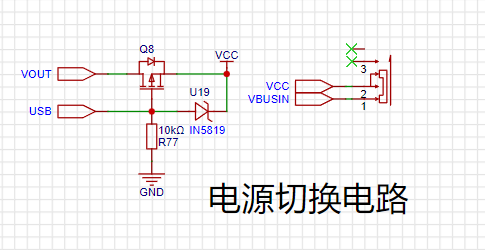
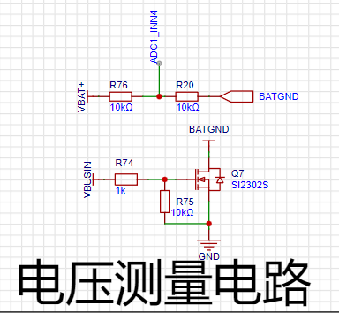
https://oshwhub.com/damihuang/AFE03 Purchase link for Hardwood Classroom H750 core board : https://www.yuque.com/yingmuketang/01/tza1xu0gk3ps5dac Additional hardware components added for portability and ease of use, eliminating the need for cables: Charging, boost, power switching, battery protection, and voltage measurement circuits have been added to the official specifications. The charging boost circuit uses the TP5400 chip, has a simple external circuit, and includes built-in boost functionality, providing power to the development board (5V 1A). The charge/discharge protection circuit uses the classic combination of DW01A and FS8205. When the battery voltage is higher or lower than the normal value, it disconnects the battery from the external circuit, effectively preventing overcharging and over-discharging. When there is no external power supply, it is powered by the battery; when an external power supply is available, it switches to external power. A battery voltage measurement circuit is added to monitor the battery's charge level.

AFE03.zip
studio_video_1700753553161.mp4
PDF_STM32H750 Oscilloscope Portable Expansion Board [Training Camp].zip
Altium_STM32H750 Oscilloscope Portable Expansion Board [Training Camp].zip
PADS_STM32H750 Oscilloscope Portable Expansion Board [Training Camp].zip
BOM_STM32H750 Oscilloscope Portable Expansion Board [Training Camp].xlsx
97020
STM32F103RCT6 Core Board Design
This is a beginner's design for an STM32F103RCT6 development board, with basic pinouts exposed [functionality verified].
Onboard Resources:
1. Four-button module (common cathode) 2. ST-LINK interface 3. Type-C and XH connectors for serial communication and power supply 4. Built-in CH340 for serial ISP 5. External FLASH and EEPROM 6. LED controlled by 2 GPIOs 7. 0.96-inch OLED screen interface (7-wire) 8. Pull-out of almost all pins of STM32F103RCT6 9. Buzzer 10. External device startup control via jumpers and buttons
Physical Dimensions
: Overall board size: 7cm x 6cm Positioning holes: M3 OLED positioning holes: M2
Functionality verified.
My blog
: https://blog.yesord.top/post/STM32F103RCT6%E6%A0%B8%E5%BF%83%E6%9D%BF%E8%AE%BE%E8%AE%A1
PDF_STM32F103RCT6 Core Board Design.zip
Altium_STM32F103RCT6 core board design.zip
PADS_STM32F103RCT6 Core Board Design.zip
BOM_STM32F103RCT6 Core Board Design.xlsx
97021
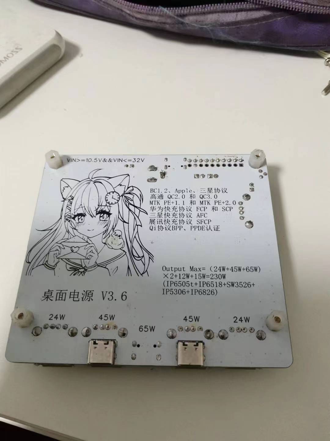
Multi-functional desktop power supply
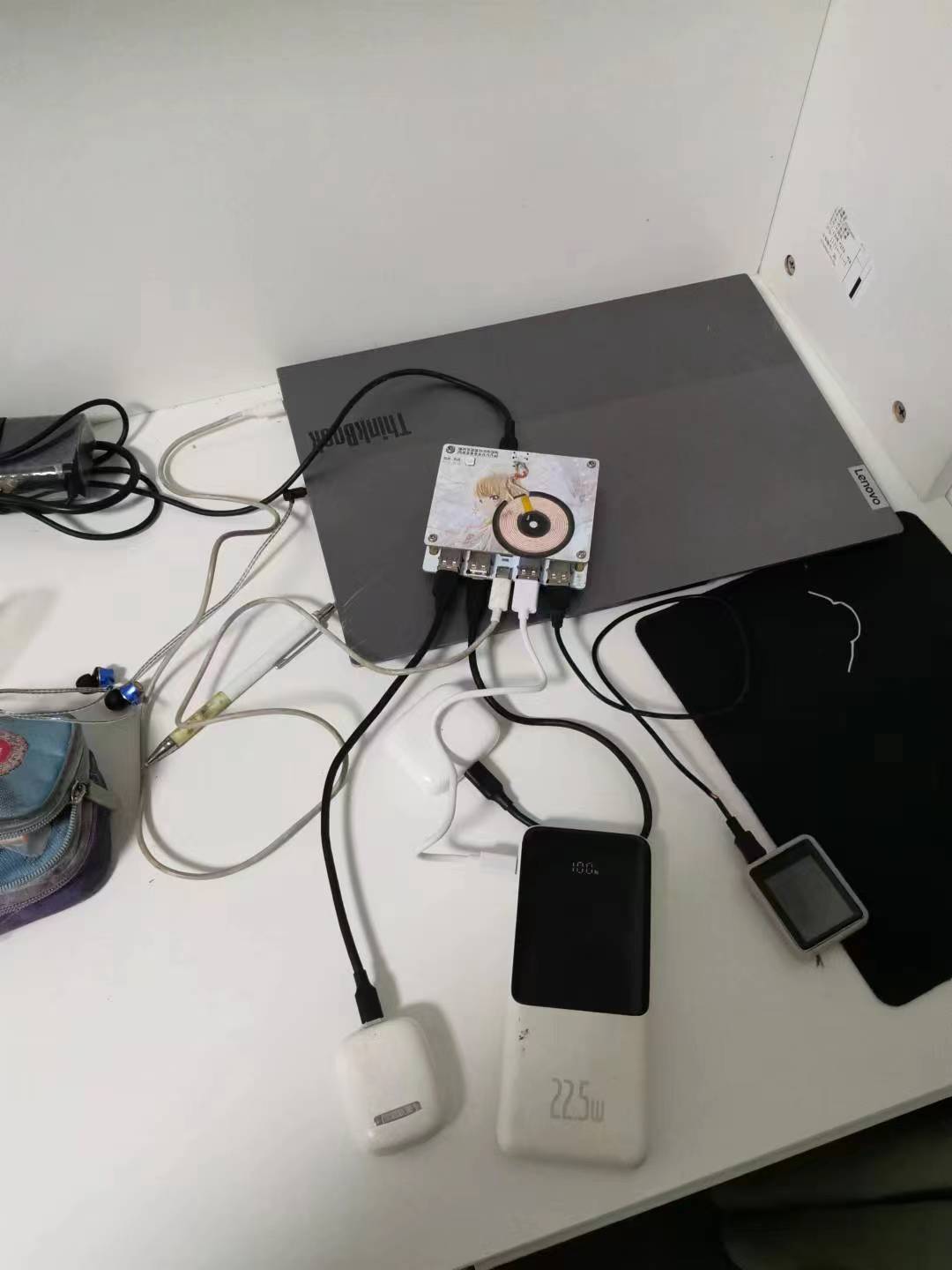
All outputs support fast charging, wireless charging, and a maximum output of 230W across all ports. An external 1S battery can be connected, and a microcontroller enables further functionality.
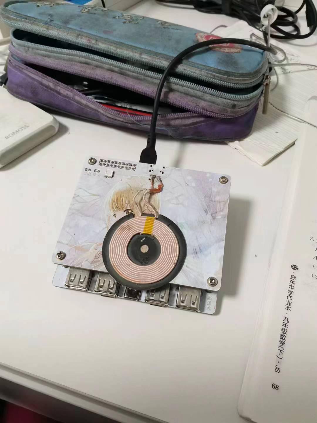
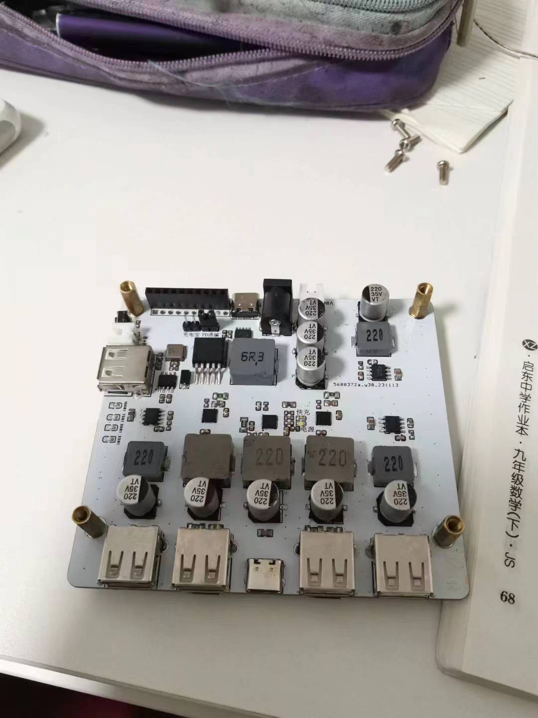
This is a desktop power supply based on IP6505T, IP6518, and SW3526. Wireless charging power reaches up to 15W. All functions have been verified to be usable
in all 0603 and higher packages, requiring no programming.
It supports PD20V spoofing, DC round port, and XH2.54 input (solder whichever you need; no need to solder all).
If you have multiple wireless charging boards, you can solder a Type-C for separate use (no need to solder in this project).
The image below is for reference only. I have tested it on laptops, mobile phones, and PowerCC devices, and it triggers the protocol normally
. Warning: The two 45W outputs (USB-A and Type-C) conflict; only one can be connected at a time. Otherwise, triggering the protocol will burn out the other output (ignore this if there is no protocol trigger). You can solder either one according to your usage.
Solder only one side of the 2×10 header pins. You can also replace it with two header pins (the rest are for your own use, such as connecting another board in the middle for signal transmission when placing a microcontroller).
When powering on, please carefully check the soldering of IP6518 and TYPE-C. I burned out a board due to bridging (crying). For
the power bank section, you can use an XH2.54 expansion
power bank and decoy header pins, shorting whichever you need.
Warning: Do not short-circuit the "decoy" when the input voltage is higher than 24V, otherwise it will burn out the CH224K.
Please use 12mm long copper pillars for connection. Nylon pillars are recommended for bottom fixing; otherwise, it is not recommended to place it on a metal object (short circuit at your own risk).
HHSDD - but it's not a steel plate, it's FR4.
ISmartWare-SW3526.pdf
ip5306.pdf
ip6505.pdf
ip6518.pdf
ip6826.pdf
CH224K.pdf
LM2596.pdf
PDF_Multifunctional Desktop Power Supply.zip
Altium_Multi-functional Desktop Power Supply.zip
PADS_Multi-functional Desktop Power Supply.zip
BOM_Multi-functional Desktop Power Supply.xlsx
97022
electronic


 京公网安备 11010802033920号

 52-PV9F2T0SS215


