 Note: This project is a secondary
  Analog input channel introduction:
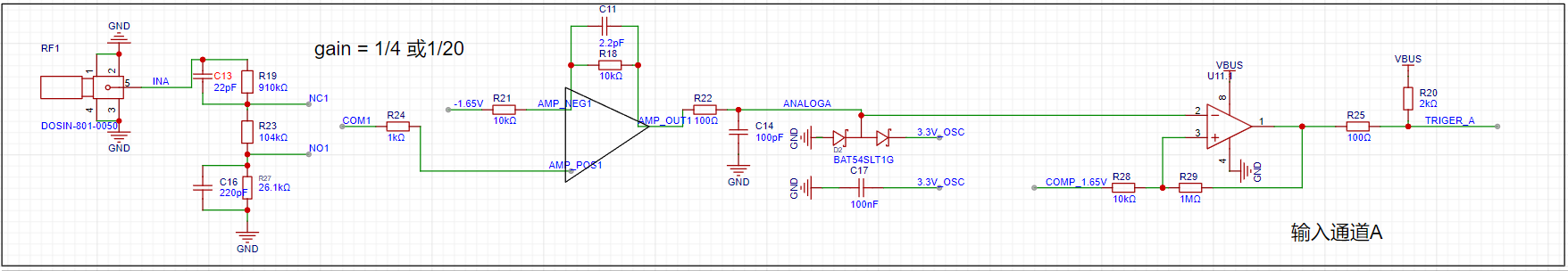
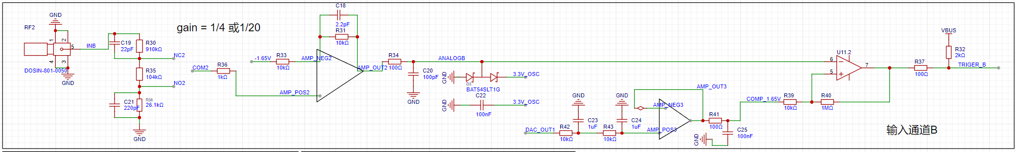 INA, INB: Oscilloscope input terminals. The pocket instrument sends an analog signal to this point. Here, a 1MΩ input impedance is achieved through a series resistor voltage divider, generating two selectable signals: one with 1/8 attenuation and the other with 1/40 attenuation.
  Gain: A selector switch that chooses a signal attenuated by 1/8 or 1/40 to enter the first-stage non-inverting amplifier. The non-inverting amplifier performs two functions: first, it amplifies the input signal at the non-inverting input by a factor of two; second, it shifts the amplified signal by 1.65V, calculated as Vo = 1.65 + 2*Vi. Therefore, the overall gain of the corresponding circuit is 1/4 or 1/10.
 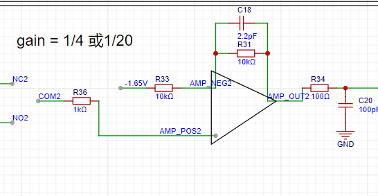 AnalogA, AnalogB: The amplified and shifted analog signals are connected to the STM32H750 development board and enter the H750's ADC.
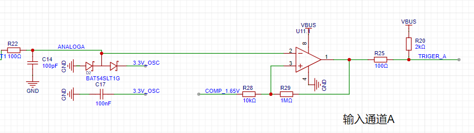
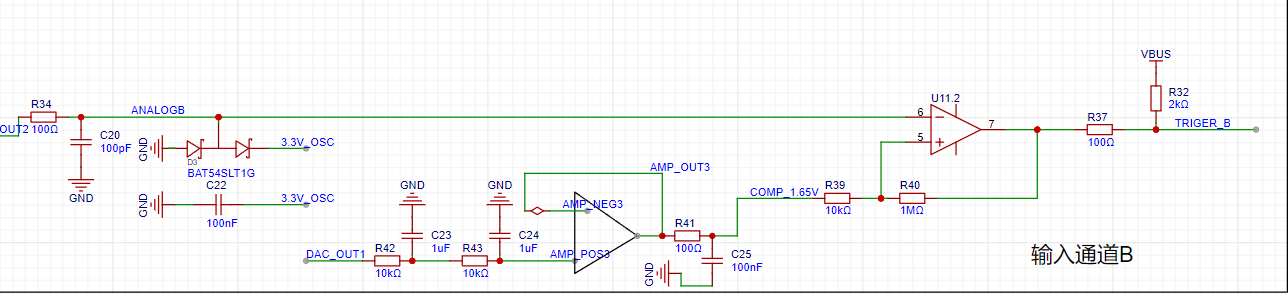 TrigerA, TrigerB: The square wave signals generated by AnalogA, AnalogB, and the DC reference level (generated by one of the H750's DACs) after passing through a comparator, enter the STM32H750's timer for frequency measurement.
  DAC_OUT2: The DC reference level, output through the STM32H750's internal DAC2 configuration.
  The STM32H750's DAC1 output ranges from 0-3.3V.
  A resistor voltage divider and buffer convert the 5V input to a low-impedance 2V output, which is then amplified by -5 times for signal shifting.
  The output amplifier performs two functions: first, it amplifies the non-inverting input by 6 times; second, it shifts the amplified signal by 6 times to -10V before outputting it, calculated as Vo = -10 + 6 * Vi.
  A voltage divider network is used to achieve better results when outputting small signals using analog voltage division.
 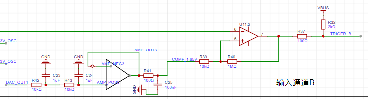 As shown in the diagram above, the H750 uses its internal DAC2 to output a 0-3.3V DC signal to compare with the waveform of channel 2 before it enters the ADC, converting the waveform of channel 2 into a square wave. This allows the H750's timer function to use the square wave signal for interrupt handling and timer capture processing.
All reference designs on this site are sourced from major semiconductor manufacturers or collected online for learning and research. The copyright belongs to the semiconductor manufacturer or the original author. If you believe that the reference design of this site infringes upon your relevant rights and interests, please send us a rights notice. As a neutral platform service provider, we will take measures to delete the relevant content in accordance with relevant laws after receiving the relevant notice from the rights holder. Please send relevant notifications to email: bbs_service@eeworld.com.cn.
It is your responsibility to test the circuit yourself and determine its suitability for you. EEWorld will not be liable for direct, indirect, special, incidental, consequential or punitive damages arising from any cause or anything connected to any reference design used.
Supported by EEWorld Datasheet
EEWorld
subscription
account

EEWorld
service
account

Automotive
development
community

Robot
development
community

About Us Customer Service Contact Information Datasheet Sitemap LatestNews


Room 1530, 15th Floor, Building B,
No.18 Zhongguancun Street,
Haidian District,
Beijing, Postal Code: 100190
China
Telephone: 008610 8235 0740
 京公网安备 11010802033920号

 KMB33F


