This is a replica of Heyh Electric's CW32 multi-function test pen. Due to cost and practical considerations, the Bluetooth connection has been removed, but an interface is provided for connecting external modules.
Here's a link to an example case:
https://oshwhub.com/heyh/dian-jing-testpen.
This was my first time participating in LCSC's training camp. Seeing that the core board required for the oscilloscope was quite expensive, and since I already had a used oscilloscope, plus I'm usually quite busy with work, I chose the multi-function test pen.
Having never designed schematics or PCBs before, this schematic was basically based on components from the LCSC online store, placing them to minimize incompatibility issues. The PCB layout followed He's electrician's examples. Since I have some basic electronics knowledge and have repaired some appliances, I made minor modifications to some components, such as changing the charging current to 200mA, as such a small battery doesn't need such a high current. I wanted to integrate some of my own ideas into the functionality, but unfortunately, I didn't have the time or energy, so I only removed the unused Bluetooth function. Later, when I have time, I can make some program modifications, such as directly booting into a frequently used mode – simple but convenient features. He's examples explain the principles in
great detail, so I won't go into further detail; they are all available in He's examples. Below are some pitfalls encountered during the production process: As a PCB design novice, I didn't understand how to adjust the spacing between slots, pads, and the board outline, resulting in numerous "X" marks. In the example case, Mr. He used his own component library, which was arranged quite compactly. The dense vias and traces caused various "X" marks, requiring careful adjustment of pad size, via and trace positions. Because I purchased a different screen than Mr. He's, a decorative border appeared on the right and bottom after programming. Later, an expert in the group suggested finding `lcd_init.c`, and I finally corrected the display after modifying and testing the start and end address settings.
Function demonstration video (updated): https://www.bilibili.com/video/BV1eG411U78D/
Some photos from the production process:
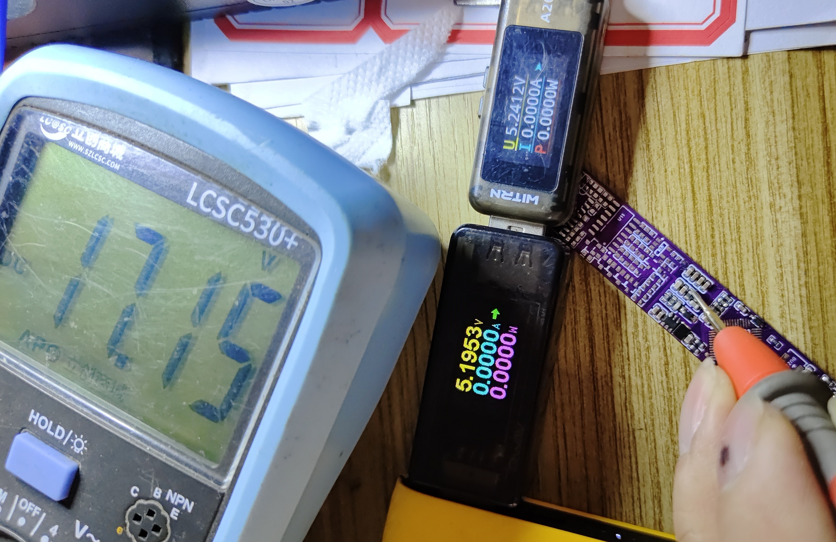
1. Charging test
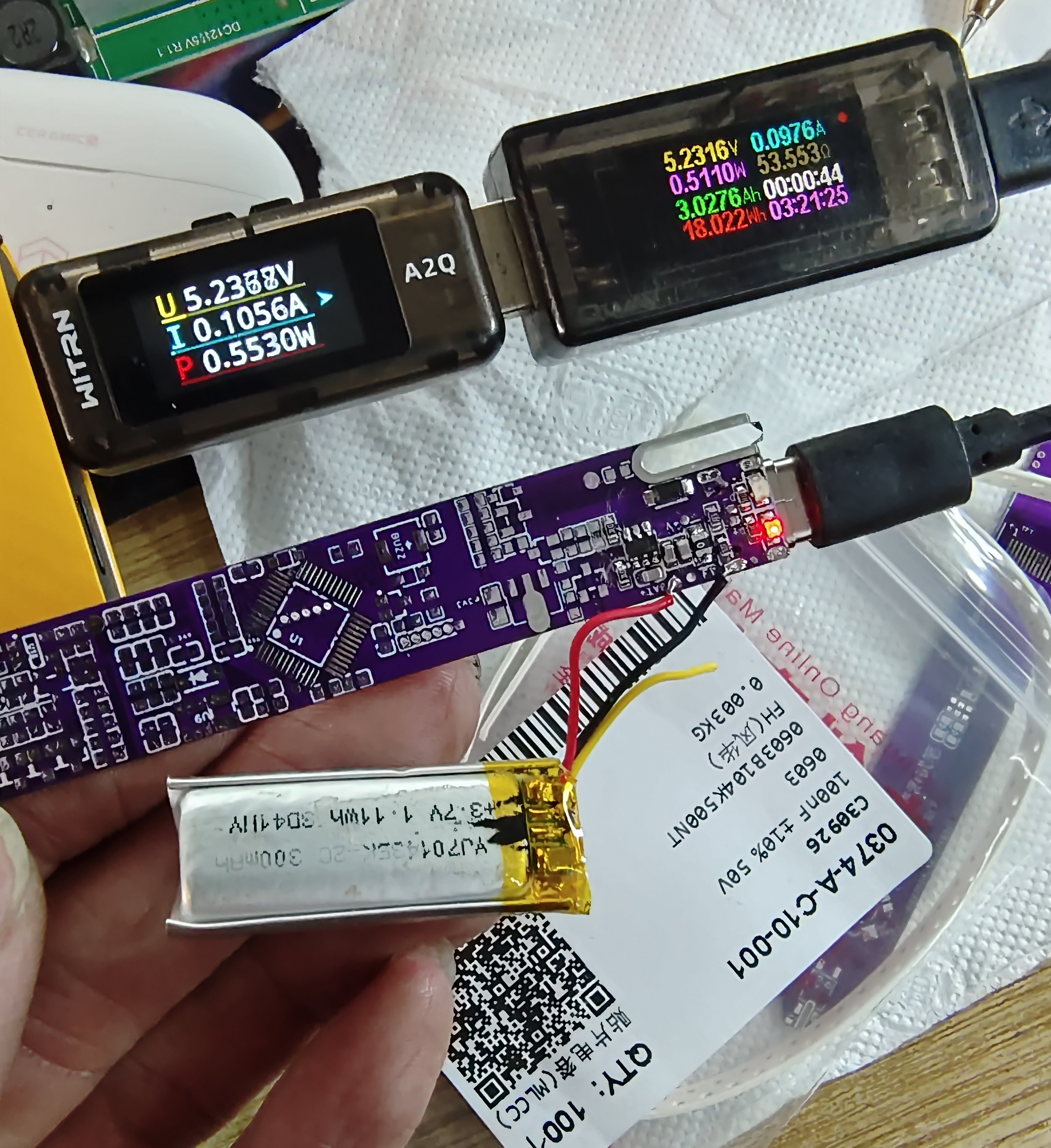
2. Boost test
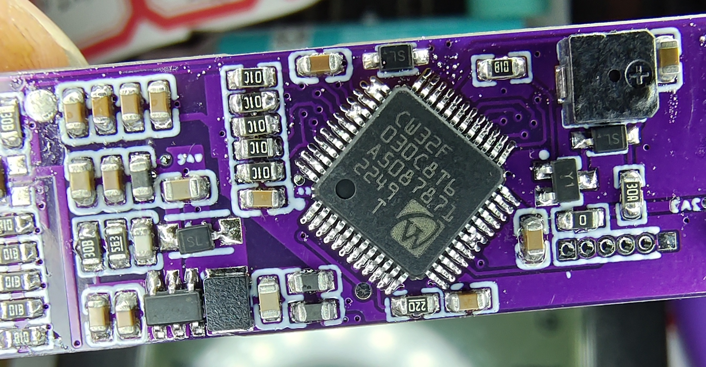
3. Close-up of the CW32 main controller; it was my first time soldering chips with such small spacing, and I only had three bridging spots, which took a long time to fix with the soldering iron
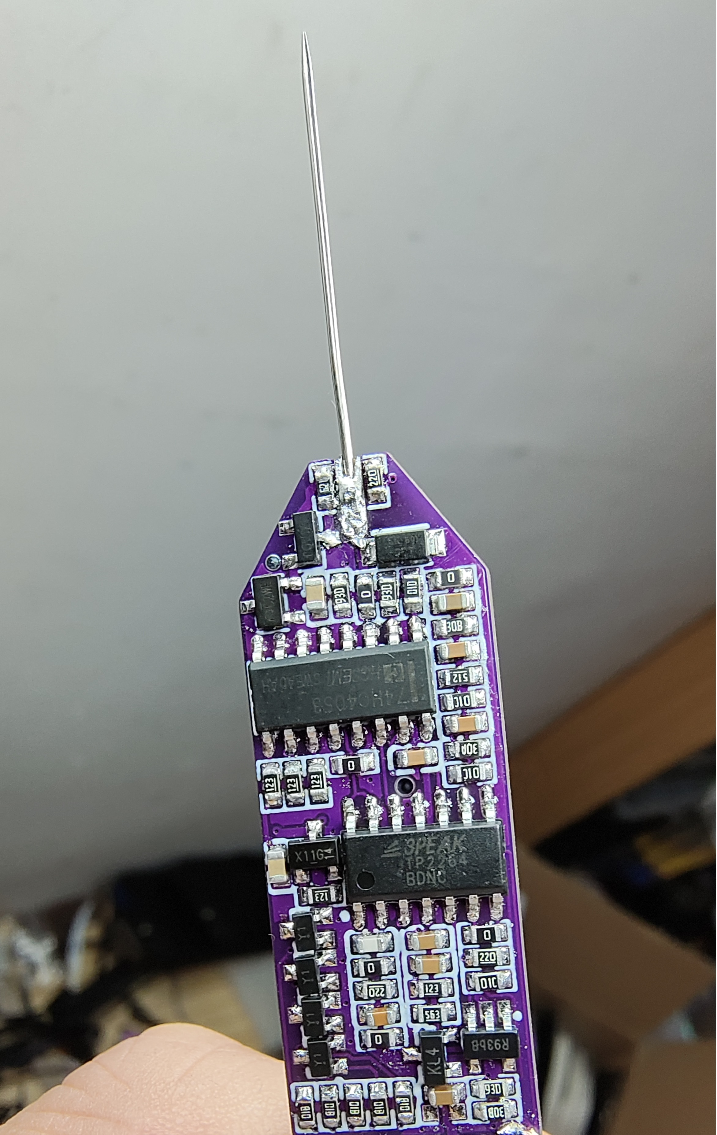
. 4. Soldering copper wires to the programming interface

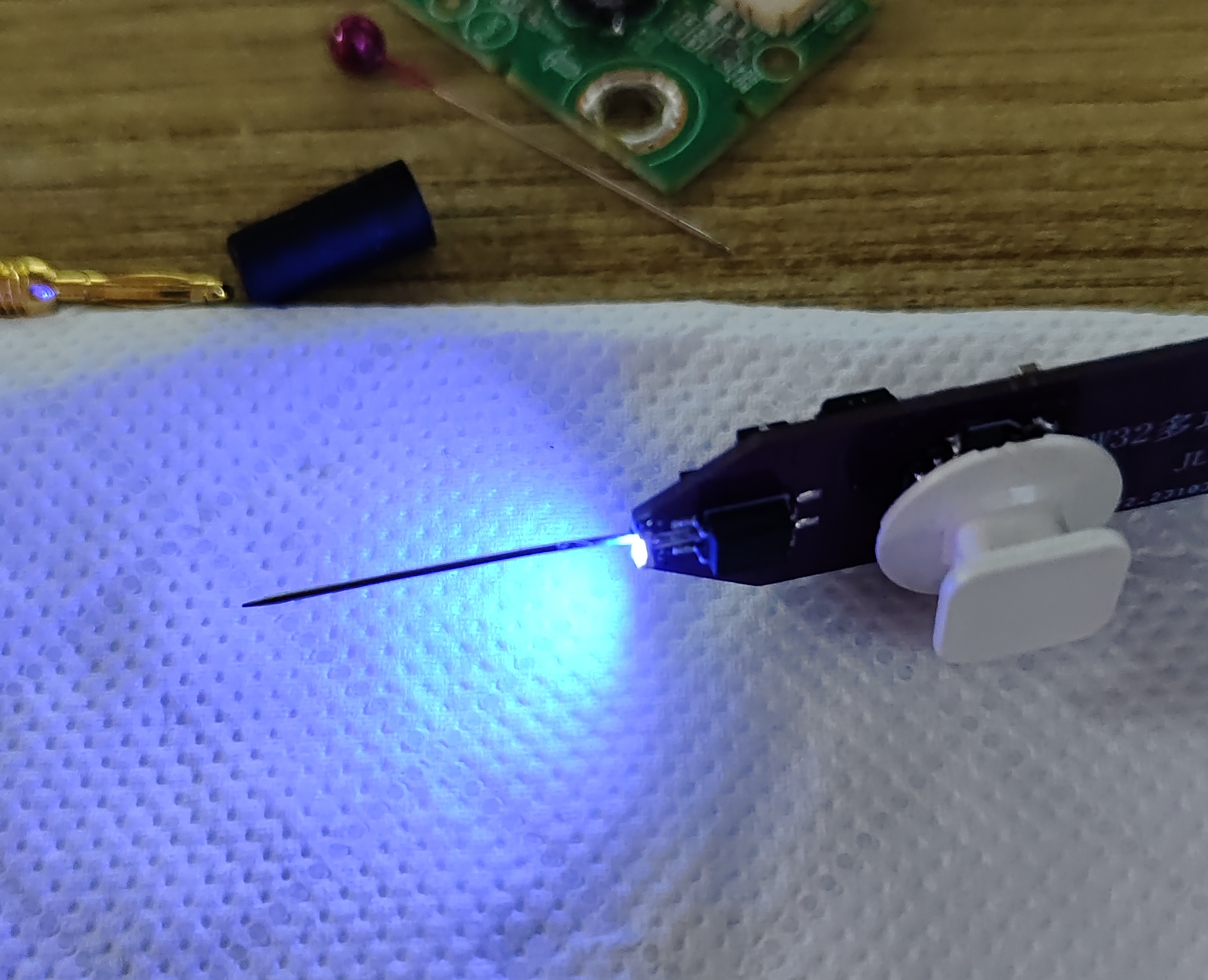
5. "Lightning rod"
6. While disassembling the 5-way switch, I found a suitable blue light on another monitor button panel and used it as is. It's quite bright and probably rarely used. The power button cap is also blue, so I brought it along. After soldering the switch, I discovered it was oxidized. I scraped the contacts after removing the case, and it worked smoothly. After putting the case back on, I found some keycaps were too soft to press, so I removed them.
7. After opening the case, I realized the original battery wouldn't fit. I found a few old Bluetooth headset batteries, charged and activated them, and got two with normal voltages and protection boards, which I directly connected. I gave the case a physical battery compartment so that if there are any extras, I can cut them off later if needed.

8. I added a layer of film to the screen window of the top case as a protective layer. I enlarged the LED light hole and used UV glue to attach it. The actual effect is good. A black case would be even better.

9. Overall appearance: the green light is quite bright. When you get close, you can see the green light from both holes, and the white case has a bright ring around it...
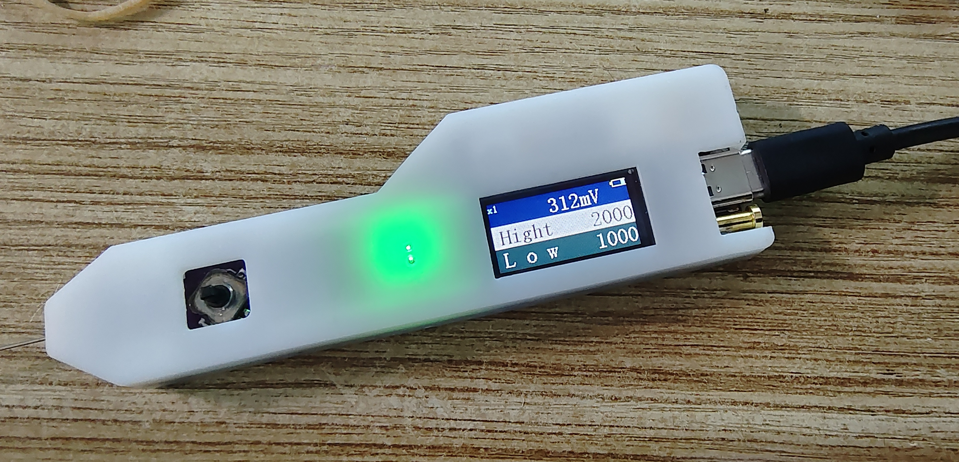
10. Fixed the screen display code.

Finally, thank you JLCPCB! For bringing us such a great event, providing such a great open source platform, domestic EDA, and free PCBs twice a month. It allowed me, a novice who could only disassemble and replace a few parts and assemble modules to repair simple circuits, to experience drawing circuit diagrams, PCBs, 3D casings, buying parts, soldering, burning programs, debugging, and making a multi-functional test pen. My hands-on skills have improved, I can understand circuit diagrams more easily, and I am more confident in repairing boards.


 京公网安备 11010802033920号

 MI-P6KY-MXZ


