 III. Functional Modules
  This chip has a maximum input voltage of 40V, an output voltage of 1.2-37V, and an output current of 3A. The schematic diagram is drawn based on the chip datasheet and is a conventional design. The only difference is the addition of a resettable fuse. I chose one with a voltage of 16V, an output current of 3A, and a trip current of 5A, because my scenario is basically below 12V. You can choose the appropriate one according to your needs.
  This chip has an input voltage of 2.4-7.3V and a maximum output current of 3A. In the design scenario, the LM2596S is used to step down the voltage and supply it to this chip, generally around 5V. Remember not to exceed 7.3V.
 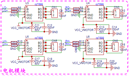 The driver chip used is RZ7899, which operates at 3-25V. This chip is used by LCSC's Liangshanpai car, and there is a lot of information about it on the open source platform.
  Three servo motors are brought out here, which can generally meet many simple scenarios.
 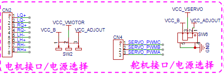 The data lines of the motor and servo need to be brought from the main controller to the driver board, because there is no MCU on the driver board.
  : Three input interfaces: DC socket, connector, and terminal block. To meet different input scenarios.
  This digital tube voltmeter module was purchased directly from Taobao; it displays voltage upon plugging in. Future design options are available.
All reference designs on this site are sourced from major semiconductor manufacturers or collected online for learning and research. The copyright belongs to the semiconductor manufacturer or the original author. If you believe that the reference design of this site infringes upon your relevant rights and interests, please send us a rights notice. As a neutral platform service provider, we will take measures to delete the relevant content in accordance with relevant laws after receiving the relevant notice from the rights holder. Please send relevant notifications to email: bbs_service@eeworld.com.cn.
It is your responsibility to test the circuit yourself and determine its suitability for you. EEWorld will not be liable for direct, indirect, special, incidental, consequential or punitive damages arising from any cause or anything connected to any reference design used.
Supported by EEWorld Datasheet
EEWorld
subscription
account

EEWorld
service
account

Automotive
development
community

Robot
development
community

About Us Customer Service Contact Information Datasheet Sitemap LatestNews


Room 1530, 15th Floor, Building B,
No.18 Zhongguancun Street,
Haidian District,
Beijing, Postal Code: 100190
China
Telephone: 008610 8235 0740
 京公网安备 11010802033920号

 TC1N974B.TB


